-
Thread
Wie am Einfachsten eine HF-Leistung von 2..5W bei 2.4GHz zur Materialprüfung ezeugen?
Festigkeit. Diese Problematik erscheint mir am leichtesten zu beheben, indem man mittels Hydraulik o.ä. die Dornen nur für die Messung einschiesst, und sie sofort danach wieder herauszieht.
ich mal machen, sobald der Versuchsaufbau steht. Allerdings nicht mit einem Magnetron, da stört u.a. die hohe Spannung die praktische (mobile) Verwendbarkeit.
-
Thread
Betreiber einer Solaranlage MUSS einspeisen?
Wasser zu verdampfen? Niemand würde Antwort a) wählen.
Ich A. schrieb im Beitrag #7449625: > Die JAZ ist aber ganz schön mies ... Tja, Realität vs. Werbeprospekt.
-
Artikel
Reichelt-Wishlist
(Auch POE) | | Fast Ethernet-Controller (DE9000A/B/E, AX88796B, ...) | FTDI High Speed Chips, z. B. FT2232H (USB - UART/FIFO IC) | * Generell mehr 1-Wire-ICs | | | | | | | | Generell mehr I2C-ICs | | * Generell mehr SPI IC | | | | * IP101 PHY von IC
fehlt eine Wertebereichssuche, anhand der man verschiedene akzeptable Werte (z.B. von 100 bis 300 mA) auswählen kann. Jetzt muss man jeden einzelnen Wert (100 mA, 105 mA, 120 mA, 150 mA, usw.) anklicken – inkl. Varianten wie "0,1 A", "0.1" und "100mA"; und der Zähler der noch nicht ausgewählten ist
-
 Bild
Bild
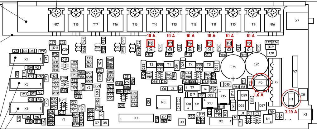
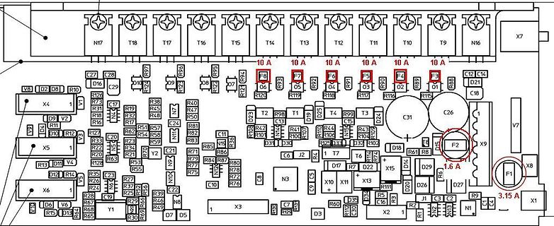
Leiterplatten-Layout eines Netzteils
N17 T18 T17 T16 T15 T14 T13 T12 T11 T10 T9 N16 X7 10 A F8 06 F7 05 F6 04 F5 03 F4 02 F3 01 1.6 A F2 X9 3.15 A F1 X8 X1 C26 C31 D24 D29 D18 D14 D26 D27 N1 3.15 A X1 X2 C16 C19 C21 C24 C26 C27 C28 C29 C31 C32 C35 C39 C46 C47 C48 C49 C50 C51 C52 C53 C54 C55
-
Thread
2 parallel geschaltete 2,4 ghz verstärker zusammenführen?
begin{pmatrix} 0&1&1\\ 1&0&0\\ 1&0&0 \end{pmatrix}. [/math] Wenn zwei Wellen mit Wellegrößen a_2 und a_3 in Port 2 und 3 einfallen, hat die aus Port 1 auslaufende Welle die Wellengröße [math] b_1=\frac{-{\rm i}}{\sqrt2}(a_2+a_3). [/math] Wenn sich a_2 und a_3 z.B. nur um eine Phase ϕ unterscheiden, also [math] a_2=a,\quad a_3=a\mathord{\rm e}^{{\rm i}\phi} [/math] ist, dann gilt [math] b_1=\frac{-{\rm i}}{\sqrt2}a(1+\mathord{\rm e}^{{\rm i}\phi} ). [/math] Also ist b_1 = 0 für ϕ = 180°, und für ϕ = 0
-
Thread
Germanium Transistor Kühlung
die Schaltung? > > http://www.muzique.com/lab/fuzzface6.gif Bisher nicht. Da sollten nur max 1mA fließen, d.h. nichts warm werden. Dann wird wohl ein Transistor defekt sein.
Peter D. schrieb im Beitrag #7446765: > Da sollten nur max 1mA fließen, d.h. nichts warm werden. Noch weniger. Die maximale Verlustleistung erreicht Q2 bei etwas unter 0,5mA, also knapp 2,2mW Verlustleistung. Bei einem thermischen Widerstand von 1K/mW (Pmax
-
Thread
Frage zu Instrumentenverstärker in LTSpice vs. Realität
machen, >> vielleicht um das 10-fache. > > Warum nicht um das 100-fache? http://web.mit.edu/6.101/www/reference/op_amps_everyone.pdf
Verstärkung 2 insgesamt also wieder 1. https://www.mikrocontroller.net/articles/Operationsverst%C3%A4rker-Grundschaltungen#Der_Subtrahierer_(Differenzverst%C3%A4rker)
-
Thread
Fehlersuche an Hameg HM8018 LC Brücke
ich mich einfach mal auf Verdacht daran gemacht. Definitiv defekt sind die beiden Transistoren T101 (dauerhaft hochohmig) und T102 (dauerhaft niederohmig). Der 10 Ohm Widerstand R130 hat ziemlich zuverlässige 560kOhm. Alle Klemmdioden scheinen noch in Ordnung zu sein. Das Ganze scheint der Ausgangsverstärker zu sein, welcher die von IC101A erzeugte Wechselspannung zum Prüfling hin verstärkt? Der Text beschreibt daß seine Transistoren des Eingangs und Ausgangsverstärkers kaputt waren. Das wären dann zusätzlich noch T401 und T402 und
-
Thread
Worin unterscheiden sich baulich Anlauf- und Betriebskondensator eines 1-Phasen-E-Motors?
> Die hiessen aber Rolling Stones. richtig = Aufmerksamkeitstest bestanden - Der Kandidat hat 101 Dalmatiner ;)
. Kolbenfresser, Auslasventil abgebrochen (hatte ich selbst), Motorlager gefressen, Anlauf-Hilfe(u.A. Anlaufkondensator) oder Anlaufentlastung defekt. > Ist klar, Kondensator, Echt wie festgestellt? > und tatsächlich quoll da > so schwarzes Zeug raus, pfuiteufel. > 30 uF steht drauf, bei 1,1 KW
-
Thread
Wer vermisst noch die analoge Funktechnik - Erinnerungen
ich habe es dann nicht mehr weiter verfolgt). Ich selbst bestehe übrigens die "AFUP" klasse E / A online Lehrgang ... nicht mit super guten Noten (Antennentechnik Schwachpunkt) aber genug (klasse A) Für "geschafft, auf zur BNETZA" und dennoch widerstrebt mir der Gedanke, mir die *Deutsche* AFU Lizenz
PC-Oszilloskope, DDS Signalgeneratoren, Frequenzzähler so klein, daß man sie überall einbauen kann u.v.a.m. Nein, ich weine der Vergangenheit keine Träne nach.
-
Thread
Altern Li-Ionen Zellen, wenn man sie nicht komplett auflädt?
(prx) A. K. schrieb im Beitrag #7439514: > Deren Lithium-Eisenphosphat-Akkus Es kommt drauf an. Li Ionen Akkus sollte man am besten bei 50-80% lagern und ergo auch in dem Bereich belassen. Wenn man ihn unter
Jahren immer auf begrenzte 100% geladen und steht so auch mal ein paar Tage rum. Das Gaze jetzt seit 101.000km und 127.000km. MfG Michael
-
Thread
OceanGate Titanic U-Boot
wirtschaft/unternehmen/diesel-affaere-ex-vw-manager-oliver-schmidt-stimmt-auslieferung-nach-deutschland-zu-a-76ee7a90-5443-4549-932a-1d98a2b7e176 Der ist sogar nach Florida geflogen, um dort Urlaub zu machen...
Once upon a time there was a very poor boy. He was so poor that he would have had nothing to play with if he had not been a boy.
-
 Bild
Bild
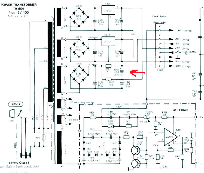
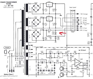
Schaltplan eines Netzteils
POWER TRANSFORMER TR 800 Type: BV 103 M65x28x0.35 BRH00 B2R0 C100 470uF TH12CU 3 35V 10 BRH01 0,86Vpp C101 470uF TH12CU 3 35V 11 BRH01 12V 6mVpp 12V 6mVpp 12V 6mVpp 12V 6mVpp 13 BRH01 14.7Vpp C102 150uF B2R0 250V R801 1k R802 250V C103 250uF 18V CT measuring voltage R804 C104 100uF 630V R805 18k R806 18k on 18-Board R810 750k R812 10k IC801 uA741 C815 0,21uF C815 0,21uF C816 0,21uF C817 0,21uF D806 D807 D808 D809 R813 150k R814 10k 0,3V
-
 Bild
Bild
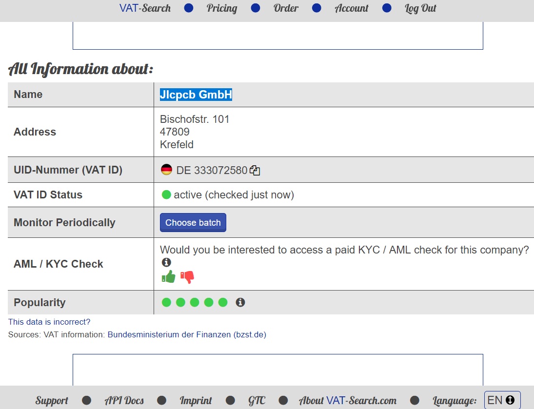
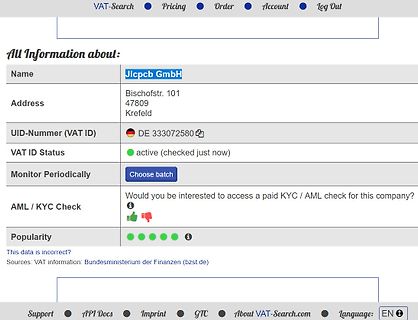
Screenshot einer Webseite mit Firmeninformationen
VAT-Search Pricing Order Account Log Out All Information about: Name Jlcpcb GmbH Address Bischofstr. 101 47809 Krefeld UID-Nummer (VAT ID) DE 333072580 VAT ID Status active (checked just now) Monitor Periodically Choose batch AML / KYC Check Would you be interested to access a paid KYC / AML check for
-
Thread
ESP32 Footprint in Target
Selber zeichnen: https://server.ibfriedrich.com/wiki/ibfwikide/index.php/Geh%C3%A4use_erstellen Wahrscheinlich eine Sache von <10 Minuten, weil du mit Raster arbeiten kannst. Außerdem kannst du dir dann ein vernünftiges Symbol mit sinnvoller Beschriftung für den Schaltplan zeichnen
joy-it.net/files/files/Produkte/SBC-NodeMCU-ESP32/SBC-NodeMCU-ESP32_dimensions.png https://components101.com/sites/default/files/inline-images/ESP32-DevKitC-Dimensions.png
-
Thread
Bewegungssensor für Fahrrad Alarm
Lautsprecher Stromkreis irgendetwas abzugreifen https://de.aliexpress.com/item/1005005532998924.html?spm=a2g0o.productlist.main.43.544a20d5Vp3eyz&algo_pvid=99a4c788-0aea-4256-9472-3b09466438de&aem_p4p_detail=2023073103204212951112056781680012098977&algo_exp_id=99a4c788-0aea-4256-9472-3b09466438de-21&pdp_npi
Ich bekomm es nicht hin. so sind es immernoch 10 mA Ruhestrom. https://tinyurl.com/29ztvwle
-
Thread
EAutosteuerung
immer so gemacht! (https://de.wikipedia.org/wiki/Balcancar#/media/Datei:Praha_hlavn%C3%AD_n%C3%A1dra%C5%BE%C3%AD,_akumul%C3%A1torov%C3%BD_voz%C3%ADk.jpg)
Zur Zeit schaffe ich nur 50.000km im Jahr. Mein Fahrzeuge haben jetzt 20.000km, 32.000km, 42.000km, 101.000km und 127.000km auf dem Tacho.
-
Thread
lwIP, STM32H7, DMA, Cache und DHCP mag nicht
do the following: 1. Change the ownership of the descriptor by setting Bit 31 of TDES3. 2. Issue a Transmit Poll Demand command. For ring mode, the application should advance the Transmit Descriptor Tail Pointer register of a channel. [/code] Da ist also die TxDescriptor Liste voll und ETH DMA
gesteuert werden. Hier https://github.com/JojoS62/Test-H743ZI2-lwip/blob/79bd3eb6f7d82179384d7a70a9411745cac3ca20/Drivers/BSP/Components/lan8742/lan8742.c#L101-L126 wird in einer for Schleife eine variable addr gegen die aus dem SMR verglichen und wenn es nicht passt wird addr inkrementiert.
-
Thread
Wassertemperatur Logger mit Lora?
die Arduino Lib das schon unterstützen 😅 https://docs.arduino.cc/learn/communication/lorawan-101 Und der Vorteil an LoRa ist ja, dass man die Gateways mitbenutzen kann, was (glaube ich) nur mit WAN funktioniert.
Koordinaten beider Standorte hier schreibst, kann man ja mal eine Abschätzung mit "Radio Mobile" o.ä. machen.
-
Thread
Resturlaub verfällt nicht mehr automatisch Gesperrt
in welchem eine Arbeitnehmerin über mehr als 20 Jahre hinweg (Rest-)Urlaubsansprüche von insgesamt 101 Tagen angesammelt hatte. Nach der Vorabentscheidung des EuGH hat das BAG den Fall entsprechend den Vorgaben des EuGH entschieden. Genaueres: https://www.bundesarbeitsgericht.de/presse/verjaehrung-von-urlaubsanspruechen-2/ (Pressemitteilung) https://www.bundesarbeitsgericht.de/entscheidung/9-azr-266-20-a/ (Vorlage des BAG an EuGH) https://www.bundesarbeitsgericht.de/entscheidung/9-azr-266-20/?highlight=9+AZR+266%2F20 (Urteil BAG nach Vorlageentscheidung des EuGH)
-
Thread
DGUV Prüfung: Gerätetester mit dokumentierter Schnittstelle?
0,15mA 3,50mA<\r><\n>Pr fergebnis Bestanden<\r><\n><\r><\n>Pr ffirma _____________________<\r><\n><\r><\n>Pr fer _____________________<\r><\n>[/code] Oder, wenn man die <\r><\n> entsprechend
0,16ê 0,30ê RISO: >19,99Mê 1,00Mê VISO: 500V IPE: <0,15mA 3,50mA Pr fergebnis Bestanden Pr ffirma _____________________ Pr fer _____________________ [/code] Sieht zu 95% ganz ok aus; abgesehen von der Präambel, die wahrscheinlich nur
-
Thread
Plattenspieler, Direktantrieb, Gleichlaufschwankungen
45 U/min geht ja alles. > Wird wohl ein lineares Poti sein 10k oder so was Auch nicht. Wie o.a. ist es ein 500 Ohm linear.
die Justage der Oscillation Frequency behandelt. Es soll ein Frequenz-Zähler an Pin 4 und 5 von IC101 geklemmt und VR101 auf 120 Hz (45U) sowie VR102 auf 88,88 Hz (33U) gesetzt werden. Zum NEC-Manual noch ein Hinweis: Über das Radiomuseum.com lade ich mir gerade die deutsche Version herunter. Dabei
-
Thread
Lineares Netzteil
Mit den 8A war ein vertipper. Meinte max 5A (8 ist eins über der 5 auf der Tastatur), werde es aber ehr bei max 3A eventuell 4A nutzen, möchte aber die Möglichkeit haben es auch mal kurzzeitig "misshandeln" zu
Realistisch wäre ca. 120W bei KK Temperatur von 75°C oder 160W bei KK Temperatur von 50°C, somit bei 35V 3,4A oder 4,6A
-
 Bild
Bild
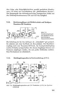
Schaltpläne von Detektorempfängern und Rückkopplungsaudion
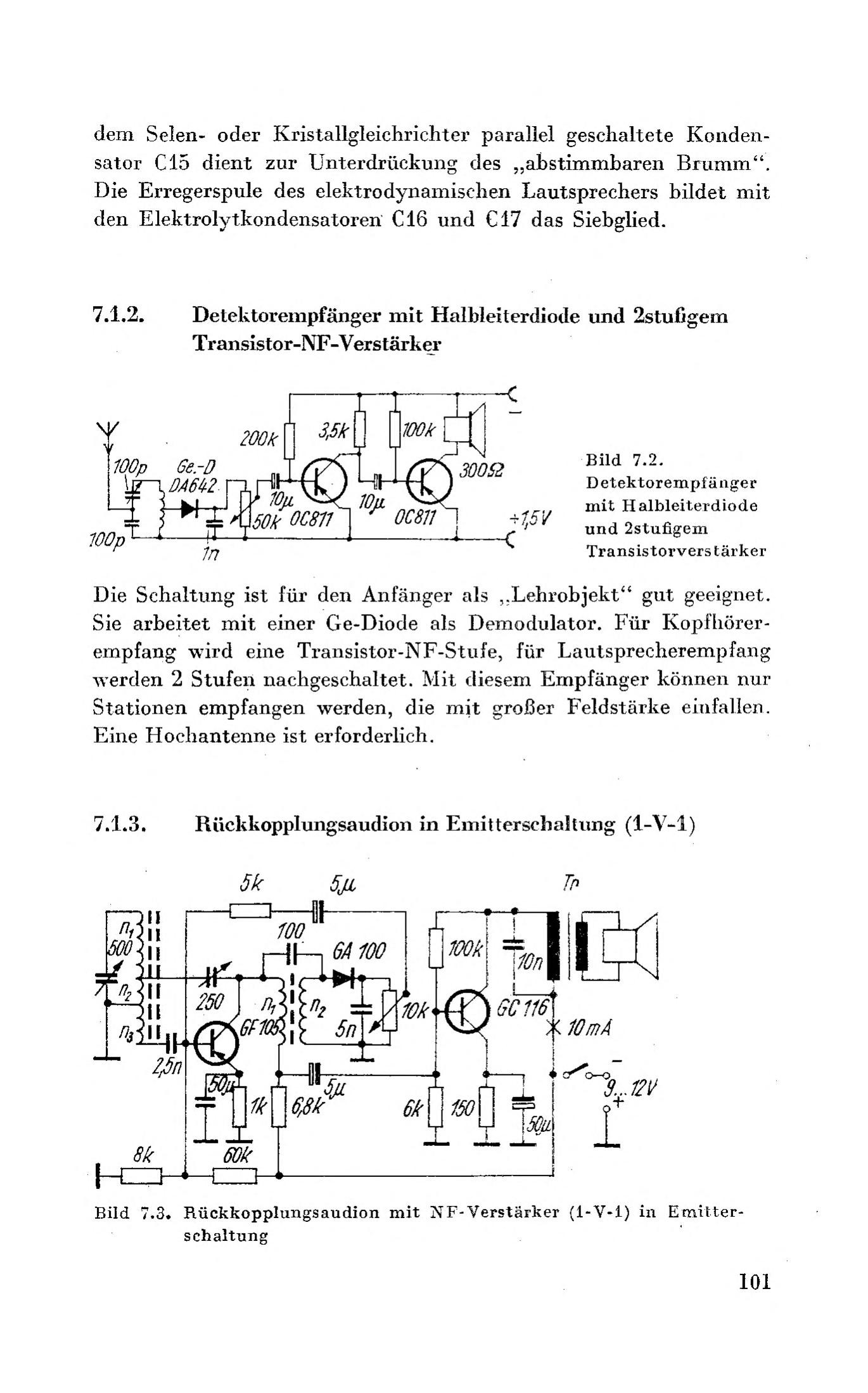
100k 300,52 Bild 7.2. Detektorempfänger mit Halbleiterdiode und 2stufigem Transistorverstärker 100p 0A642 10u 10u +1,5V 50k OC811 OC811 Die Schaltung ist für den Anfänger „Lehrobjekt“ gut geeignet. Sie arbeitet mit einer Ge-Diode als Demodulator. Für Kopfhörerempfang wird eine Transistor-NF-Stufe nachgeschaltet
-
Thread
Review Filter- und Verstärkerschaltung
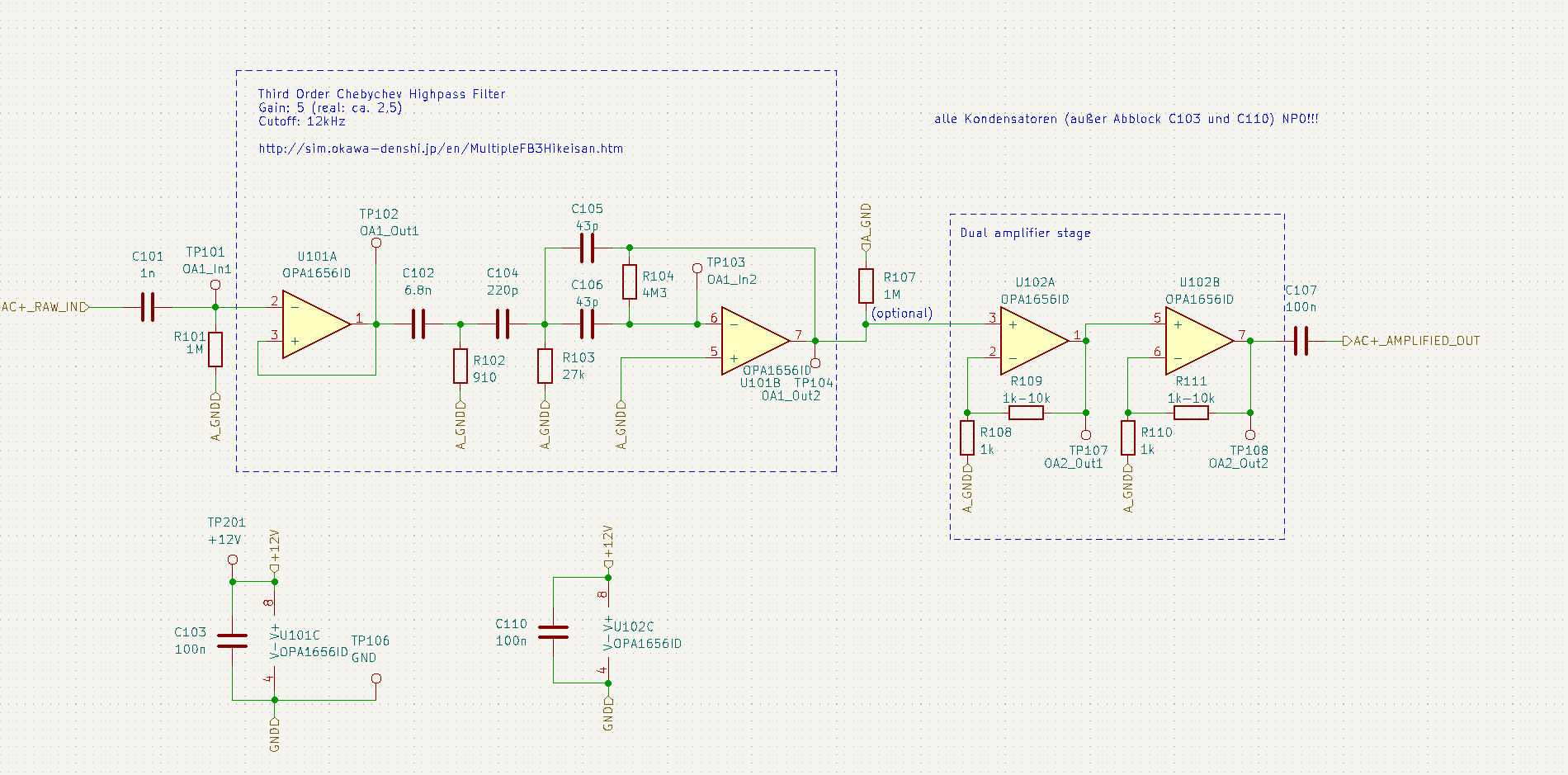
U101A: Eingänge vertauscht. U101B: Bsp. mit praxisgerechteren Bauteile im Anhang.
ohhh, wirklich, dieser fehler mit den vertauschten eingängen bei u101a hätte mich sehr geärgert! und test mit den "praxisgerechten" bauteilen bringt gewünschte resultate! danke, @r0bm!
-
 Bild
Bild
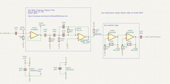
Schaltplan eines Third Order Chebyshev Highpass Filters
en/MultipleFB3Hikeisan.htm alle Kondensatoren (außer Abblock C103 und C110) NPD!!! TP102 OA1_Out1 C101 1n R101 1M A_GND U101A OPA1656ID C102 6.8n C104 220p R102 910 A_GND A_GND C105 43p R104 4M3 TP103 OA1_In2 U102A 1M OPA1656ID A_GND Dual amplifier stage U102B OPA1656ID C107 100n OA2_Out1 OA2_Out2 AC+AMPLIFIED_OUT R107 R109 R111 1k-10k 1k-10k TP104 TP107 TP108 R108 1k A_GND A_GND +12V C103 100n U101C OPA1656ID GND TP201 +12V C110 100n U102C OPA1656ID GND
-
 Bild
Bild
Nahaufnahme von Leistungshalbleitern auf einer Leiterplatte
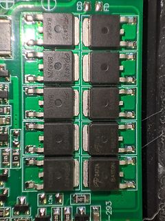
BA908C, BA8U2N, BA6X4B, BA0X26, PD472, PD472A, BA1S9N, 105, 101, 293