-
PDF
PCA9306.pdf
translator 12 Package outline SO8: plastic small outline package; 8 leads; body width 3.9 mm SOT96-1 D E A X c y H E v M A Z 8 5 Q A 2 (A3) A A 1 pin 1 index θ Lp 1 4 L e b w M detail X p 0 2.5 5 mm scale DIMENSIONS (inch dimensions are derived from the original mm dimensions) UNIT A A A A b c D (1) E (2)
in „[V] ONSEMI Dual bidirectional PCA9306 I2C-bus and SMBus Voltage-level translator (30St für10€)“ · Markt ·
-
PDF
PCA9306.pdf
translator 12 Package outline SO8: plastic small outline package; 8 leads; body width 3.9 mm SOT96-1 D E A X c y H E v M A Z 8 5 Q A 2 (A3) A A 1 pin 1 index θ Lp 1 4 L e b w M detail X p 0 2.5 5 mm scale DIMENSIONS (inch dimensions are derived from the original mm dimensions) UNIT A A A A b c D (1) E (2)
in „[V] .Dual bidirectional PCA9306 I2C-bus and SMBus voltage-level translator (30St/10€)“ · Markt ·
-
PDF
PCA9306.pdf
translator 12 Package outline SO8: plastic small outline package; 8 leads; body width 3.9 mm SOT96-1 D E A X c y H E v M A Z 8 5 Q A 2 (A3) A A 1 pin 1 index θ Lp 1 4 L e b w M detail X p 0 2.5 5 mm scale DIMENSIONS (inch dimensions are derived from the original mm dimensions) UNIT A A A A b c D (1) E (2)
in „[V] ca. 190St.Dual bidirectional PCA9306 I2C-bus and SMBus voltage-level translator (20St/8€)“ · Markt ·
-
PDF
PCA9306.pdf
translator 12 Package outline SO8: plastic small outline package; 8 leads; body width 3.9 mm SOT96-1 D E A X c y H E v M A Z 8 5 Q A 2 (A3) A A 1 pin 1 index θ Lp 1 4 L e b w M detail X p 0 2.5 5 mm scale DIMENSIONS (inch dimensions are derived from the original mm dimensions) UNIT A A A A b c D (1) E (2)
in „V] ca. 170 St.Dual bidirectional PCA9306 I2C-bus and SMBus voltage-level translator (20St/8€)“ · Markt ·
-
PDF
PCA9306.pdf
translator 12 Package outline SO8: plastic small outline package; 8 leads; body width 3.9 mm SOT96-1 D E A X c y H E v M A Z 8 5 Q A 2 (A3) A A 1 pin 1 index θ Lp 1 4 L e b w M detail X p 0 2.5 5 mm scale DIMENSIONS (inch dimensions are derived from the original mm dimensions) UNIT A A A A b c D (1) E (2)
in „[V] Konvolut Dual bidirectional PCA9306 I2C-bus and SMBus voltage-level translator“ · Markt ·
-
PDF
S852T_Temic.pdf
f = 500 MHz T 5.2 GHz Collector-base capacitance VCB = 1 V, f = 1 MHz Ccb 0.25 pF Noise figure ZS= ZSopt f = 945 MHz, V CE= 3 V,CI = 1 mA Fopt 1.8 dB V CE= 2 V,CI = 1.5 mA Fopt 2.0 dB ZS= ZSopt f = 450 MHz Fopt 1.1 dB V = 2 V, I = 0.5 mA CE C Power gain VCE = 3 V,CI = 1 mA, f = 945
in „ISM Empfänger mit kleinstem Standby“ · HF, Funk und Felder ·
-
PDF
tlv320aic12k.pdf
functionally identical with and OUTM1 9 9 13 13 O complementary to OUTP1. This differential output can drive a maximum load of 600 . This output can also be used alone for single-ended operation. Noninverting output of the DAC. This differential output can drive a OUTP1 10 10 14 14 O maximum load of 600 . This
in „PHILIPS VP5500 VoIP Telefon bei Pollin“ · Mikrocontroller und Digitale Elektronik ·
-
PDF
74hc4052.pdf
SO16: plastic small outline package; 16 leads; body width 3.9 mm; body thickness 1.47 mm SOT109-3 D E A X c y HE v M A Z 16 9 A 2 (A3) A A1 pin 1 index L p 1 8 L e b w M detail X p 0 2.5 5 mm scale DIMENSIONS (inch dimensions are derived from the original mm dimensions) A (1) (1) (1) UNIT max. A1 A2 A3
in „Audio Umschalter“ · Mikrocontroller und Digitale Elektronik ·
-
PDF
WP-MSK200-M.pdf
77℉) Capacity Retention Characteristic (%) 120 100 0.05CA 100 0.1CA t 0℃(32℉) 0.25CA c75 % 80 0.6CA p 10℃(50℉) i 1CA a a 60 2CA g50 20℃(68℉) a i C 40 a 40℃(104℉30℃(86℉) m 20 R25 0 -20 -10 0 10 20 30 40 50 ℃ 0 3 6 9 12 15 18 -4 14 32 50 68 86 104 122 ℉ Storage Time (months) Temperature Cycle Service Life 120 100 y i 80 a a 60 C DischarDischarge Depth 50%harge Depth 30% 40 (1) Discharge : 5HR rate (0.17CA) 20 (3) End of life discharge voltage : 1.65 Vpc (4) Temperature : 25±2℃ 0 200 400 600 800 1000 1200 1400 1600 Number
in „100A Stromquelle für Messzwecke“ · Analoge Elektronik und Schaltungstechnik ·
-
PDF
Infineon-IRFHS8342-DataSheet-v01_01-EN.pdf
25°C Continuous Drain CurrenGS@ 10V (Package Limited) 8.5d D C(Bottom) IDM Pulsed Drain Current 76 P DT =A25°C Power Dissipation 2.1 Power Dissipation W P DT =A70°C 1.3 Linear Derating Factor 0.02 W/°C T Operating Junction and -55 to + 150 J °C TSTG Storage Temperature Range Notes through are on page
in „IC identifizieren“ · Analoge Elektronik und Schaltungstechnik ·
-
PDF
HCPL_7520.pdf
mW) ensuredbyprotectivecircuitswithintheapplication.SurfaceMountClassificationsisClassAin T 700 I (mA) R S accordancewithCECC00802. U 600 2.RefertotheoptocouplersectionoftheIsolationandControlComponentsDesigner’sCatalog, T underProductSafetyRegulationssection, P 500 (IEC/EN/DIN EN 60747-5-2) for a detailed
in „Isolierte Netzspannungsmessung“ · Analoge Elektronik und Schaltungstechnik ·
-
PDF
piezo-circuits.pdf
kHz 10Vp-p SQ. 30cm 17nF ± 30% KBS-20DB-5A 75dB Min. 5.000 kHz 10Vp-p SQ. 30cm 10nF ± 30% KBS-27DB-2A-5 70dB Min. 2.500 kHz 10Vp-p SQ. 30cm 46nF ± 30% KBS-27DB-3A 75dB Min. 3.000 kHz 10Vp-p SQ. 30cm 20nF ± 30%
in „Piezo Treiber“ · Analoge Elektronik und Schaltungstechnik ·
-
PDF
piezo-circuits.pdf
kHz 10Vp-p SQ. 30cm 17nF ± 30% KBS-20DB-5A 75dB Min. 5.000 kHz 10Vp-p SQ. 30cm 10nF ± 30% KBS-27DB-2A-5 70dB Min. 2.500 kHz 10Vp-p SQ. 30cm 46nF ± 30% KBS-27DB-3A 75dB Min. 3.000 kHz 10Vp-p SQ. 30cm 20nF ± 30%
in „Piezo-Disc an 230V AC“ · Analoge Elektronik und Schaltungstechnik ·
-
PDF
piezo-circuits.pdf
kHz 10Vp-p SQ. 30cm 17nF ± 30% KBS-20DB-5A 75dB Min. 5.000 kHz 10Vp-p SQ. 30cm 10nF ± 30% KBS-27DB-2A-5 70dB Min. 2.500 kHz 10Vp-p SQ. 30cm 46nF ± 30% KBS-27DB-3A 75dB Min. 3.000 kHz 10Vp-p SQ. 30cm 20nF ± 30%
in „Relay Schalten mit kleiner Spannung“ · Analoge Elektronik und Schaltungstechnik ·
-
PDF
10n120bnd.pdf
SOA SSOA TJ= 150 C, R G 10Ω, V GE = 15V, 55 - - A L = 400µH, VCE(PK)= 1200V Gate to Emitter Plateau Voltage V GEP IC= 10A, VCE = 600V - 10.4 - V On-State Gate Charge QG(ON) IC= 10A, VGE = 15V - 100 120 nC V = 600V CE VGE = 20V - 130 150 nC Current Turn-On
in „Netzteil mit IGBT“ · Analoge Elektronik und Schaltungstechnik ·
-
PDF
IRF1404.pdf
Effective Transient Thermal Impedance, Junction-to-Case www.irf.com 5 IRF1404 15V J500 m D ( TOP 49A g 101A L DRIVER 1200 BOTTOM 121A VDS n E h R G D.U.T + c -VDD a900 IAS A a 20V v tp 0.01Ω A l600 u Fig 12a. Unclamped Inductive Test Circuit P V(BR)DSS l n tp S300 , S A E 0 25 50 75 100 125 150 175
in „MOSFET wird sehr heiß“ · Analoge Elektronik und Schaltungstechnik ·
-
PDF
OKI_C1937-01.pdf
10% • Package options: 40-pin plastic DIP (DIP40-P-600-2.54) (Product name: MSC1937-01RS) 44-pin plastic QFP (QFP44-P-910-0.80-K) (Product name: MSC1937-01GS-K) 1/16 B ¡ L O C S K e D m A o G n R u M c o r SGA DATA 6·16 SGB DISPLAY 64·16 SEGMENT SGC
in „SPI VFD-Display OKIC1937-01“ · Mikrocontroller und Digitale Elektronik ·
-
PDF
1767fas.pdf
Current, MaximumLoad Current, Current Limit Foldback V = 5V V = 2.5V OUT OUT 2.0 40 1.5 1.5 A B 1.3 L = 4.7µH T 1.5 30 N A L = 4.7µH A 1.3 E P T T R SWITCH CURRENT T E 1.1 E U U R R L = 2.2µH K 1.0 20 R U U 1.1 E E C C P T U 0.9 L = 2.2µH U C µ T T L = 1.5µH I ) O O S 0.5 10 0.9 FB CURRENT 0.7
in „LT Spice ein IC von Texas Insturments einbinden“ · Analoge Elektronik und Schaltungstechnik ·
-
PDF
56001-BM2_KM.pdf
G A A A / zuachtenist,dassdieverschiedenenTran- 3 K C C D D C E N E C F D E sistortypen nicht verwechselt werden. E B B P V / 6/ P P C C I Danach geht es mit den SMD-Wider- 3 T T B B P 5 4 6 2 + + 4 L L P M / P D D D C C C C ständenweiter,derenWiderstandswertdi- V V 4 T T/ B 4 O S 1B P D D P X D D D D C C / 2/1/0/ O O / M / O O 0 A A 5 K I I / R D D S S D D D AD rekt auf dem Gehäuse aufgedruckt ist. Die
in „CCD-oder CMOS-Kamerasignal auswerten lassen ( in V umwandeln“ · Mikrocontroller und Digitale Elektronik ·
-
PDF
SF_ISF.pdf
-217F at 25 °C, GB Nfeicolecm Efuclmt Top View grid: 0.1 x 0.1 in (2.54 x 2.54 mm) Fo▯lsponfoucm 0.600 (15.24) Package A 0.400 7 5 A1 A2 Operating Temperature • -40 °C to +85 °C, full load (10.16) . 4 0 ( Storage Temperature • -55 °C to +125 °C 4 2 9 0 5 5 4 2 Side View 10 9 8 7 6 10 7 0 1 0 ( Top View
in „Verständnissproblem bei Schaltplan ISF0305A“ · Analoge Elektronik und Schaltungstechnik ·
-
PDF
3_3-5V.pdf
-217F at 25 °C, GB Nfeicolecm Efuclmt Top View grid: 0.1 x 0.1 in (2.54 x 2.54 mm) Fo▯lsponfoucm 0.600 (15.24) Package A 0.400 7 5 A1 A2 Operating Temperature • -40 °C to +85 °C, full load (10.16) . 4 0 ( Storage Temperature • -55 °C to +125 °C 4 2 9 0 5 5 4 2 Side View 10 9 8 7 6 10 7 0 1 0 ( Top View
in „Das große ADC Quiz“ · Mikrocontroller und Digitale Elektronik ·
-
PDF
7637.pdf
A 220 nF. D 42⋅10 A. B 22 nF. TA102 0,00042 A entspricht C 220 pF. . -6 D 22 pF. A 42010 A. B 42010 A. . -5 TA207 3,75 MHz sind C 42010 A. A 3750 kHz. D 4210 A. B 375 kHz. C 0,0375 GHz. TA103 100 mW entspricht
in „Arbeit im Ausland als Elektroniker“ · Ausbildung, Studium & Beruf ·
-
 Bild
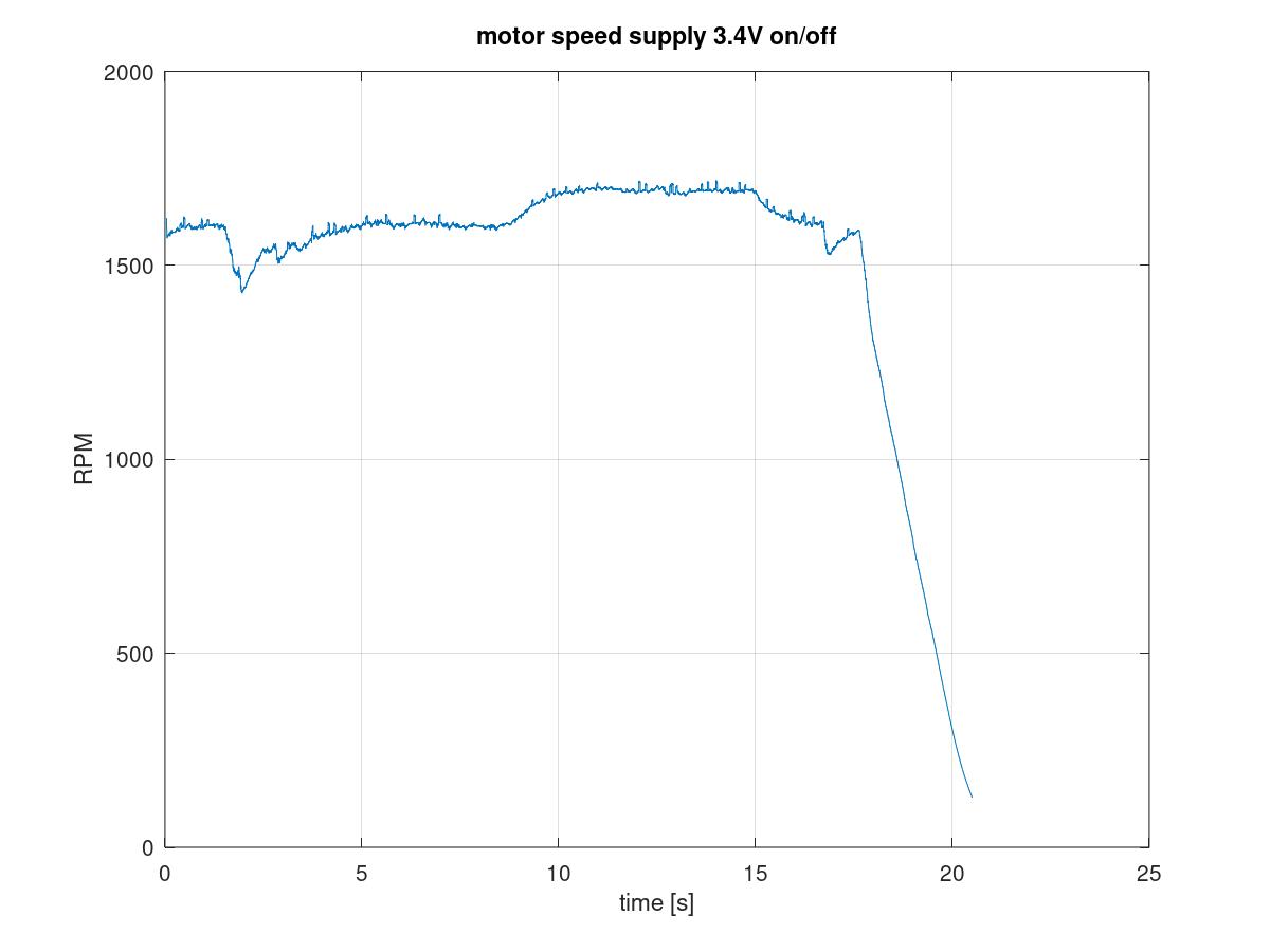
Diagramm der Motordrehzahl über der Zeit
motor speed supply 3.4V on/off 2000 1500 1000 500 0 0 5 10 15 20 25 RPM time [s]
in „Bastelmotor Gleichstrommotor Modell“ · Offtopic · · Screenshots
-
PDF
Voltage-Reference_Filters_sbva002.pdf
DRIVING DYNAMIC LOADS the reference to reduce the noise bandwidth by 100/1 (from SUCH AS HIGH-SPEED A/D CONVERTERS 1MHz to 10kHz, for example) can reduce the noise by 10/ 1 (from 600 Vp-p to 60 Vp-p). IMPROVED NOISE FILTERING The conventional circuit, shown in Figure 1, uses a single- BETTER ACCURACY
in „Frage zu Spannungsreferenzen“ · Analoge Elektronik und Schaltungstechnik ·
-
PDF
AOB0000C27.pdf
□□□E Insulated P P2 (14A/14Z, 12A/12Z, 1AB/1Z) D Lead A H F P1 H 1 W fd W P0 fD 0 Dimensions (mm) Dimensions (mm) Dimensions (mm) Dimensions (mm) Dimensions (mm) P 12.7±1.0 W 18.0±0.5 14A/14Z 12max. 14A/14Z 6.35 +–0.35
-
PDF
180023-da-01-en-ACRICHE_LED_110V_COOL_WHITE_AW2214.pdf
temperature of lead frame should be below 70 ℃. 6 Rev 00 – 2007 / 06 www.acriche.com Color spectrum, T =25ºC A 1. Pure White 1.0 P ure W hite S ta nd a rd e ye re spo nse curv e 0.8 r e o P a o 0.6 t t c b p r S s 0.4 e D t l e 0.2 R 0.0 300 400 500 600 700 800 900 W a v e le n g th ( n m ) 2. Warm white 1.0 W a rm w h ite W a rm w h ite (C R I8 0 ) 0.8 r w o P n 0.6 a i t t e b p t S i 0.4 v D t l e 0.2 R 0.0 400 500 600 700 800 W a v e le n g th ( n m ) 7 Rev 00 – 2007 / 06 www.acriche.com Electrical Characteristics
in „Samsung Hochvolt AC LED Erfahrungen?“ · Analoge Elektronik und Schaltungstechnik ·
-
PDF
AD7606_7606-6_7606-4.pdf
(INL 0.3×VDRIVE V Input CurrentINI ) ±2 µA 7 Input Capacitance IN ) 5 pF LOGIC OUTPUTS Output HighVoltage (OH) ISOURCE100 µA VDRIVE.2 V Output LowVoltage (VOL ISINK100 µA 0.2 V Floating-State Leakage Current ±1 ±20 µA 7 Floating-State Output
in „STM32 Parallel Bus ADC“ · Mikrocontroller und Digitale Elektronik ·
-
PDF
LIFEPO4_18650FPZ_DB.pdf
88.4%) 2.0 Internal 1.8 Resistance ğ▯▯NΩ max. at 1000Hz 1.6 Charging Voltage ğ▯▯▯▯ ▯▯▯▯7 0 200 400 600 800 1000 1200 Ambient ğCharging ğ▯▯▯ j▯▯▯ ¥ Temperature Capacity / mAh Range Discharging ğ▯▯▯ j▯▯▯ ¥ Storage ğ▯▯ j▯▯▯ ¥ 3.Battery drawing 18.2 3.8 1200 ) ▯▯$IBSHJOH▯$IBSBDUFSJTUJD▯ 1100 h m 9 3.6 Capacity 1000 y 900 c p V 3.4 Voltage 800 a / 700 C Current 600 / g 3.2 A l 500 m V 400 t 5 3.0 e 4 300 u 6 200 C 2.8 100 0 0 20 40 60 80 100 120 140 unitğmm time / min :6/50/(▯1PXFS▯$P▯ -UE5FM▯▯▯▯▯▯▯▯▯▯▯▯▯▯▯▯'BY▯▯▯▯▯▯▯▯▯▯▯
in „Fest integrierte Balancer Schaltung mit Tiefentladeschutz“ · Analoge Elektronik und Schaltungstechnik ·
-
PDF
ads5240.pdf
. 9 ADS5240 www.ti.com SBAS326C–JUNE 2004–REVISED DECEMBER 2004 PIN CONFIGURATION Top View HTQFP T A L X S L A D S S S C D / F F M T S V C D S V V V V D V N E E C S V A S S C A A A A A A I R R V I A 64 63 62 61 60 59 58 57 56 55 54 53 52 51 50 49 AVDD 1 48 AVDD IN1P 2 47 INN IN1N 3 46 IN4P 4 45 AVSS
in „Pipeline A/D-Wandler ADS5240 Verständnisproblem Analoge Eingangsspannung“ · Analoge Elektronik und Schaltungstechnik ·
-
PDF
bq25504.pdf
designed to efficiently acquire and manage the microwatts (µW) – Ultra-low quiescent current: I <Q330 nA (Typical) to miliwatts (mW) of power generated from a variety of DC sources like photovoltaic (solar) or thermal – Cold-start voltage: V IN ≥ 600 mV (typical) electric generators. The BQ25504 is the
in „CJMCU-25504 Jumper setzen“ · Analoge Elektronik und Schaltungstechnik ·
-
PDF
MOC3041.pdf
Current Figure 2. On-State Characteristics 0 1.6 800 1 F = 30mA M 600 TA= 25°C , 1.5 M ) O ( 1.4 m 400 C E T 0 A E 200 3 L 1.3 R M V U , D 1.2 A = -40°C E 0 M A A O W TA= 25°C S -200 C O 1.1 N 3 - T = 85°C , 3 VF 1.0 A I -400 M -600 M 0.9 C 0.8 -800 3 0.1 1 10 100
in „Triac am atmega anstelle MOC3041 und BTA08-400“ · Analoge Elektronik und Schaltungstechnik ·
-
PDF
94874_MOC3043_OptoTriac.pdf
Current Figure 2. On-State Characteristics 0 1.6 800 1 F = 30mA M 600 TA= 25°C , 1.5 M ) O ( 1.4 m 400 C E T 0 A E 200 3 L 1.3 R M V U , D 1.2 A = -40°C E 0 M A A O W TA= 25°C S -200 C O 1.1 N 3 - T = 85°C , 3 VF 1.0 A I -400 M -600 M 0.9 C 0.8 -800 3 0.1 1 10 100
in „Triac Probleme mit MOC3043“ · Analoge Elektronik und Schaltungstechnik ·
-
PDF
sn75lvds82.pdf
ambient air temperatures of 0°C to 70°C. FUNCTIONAL BLOCK DIAGRAM Serial-In/Parallel- Out Shift Register A1P A1M Serial In D0 A, B, ...G D1 CLK D2 D3 D4 Serial-In/Parallel- D6 Out Shift Register D7 A2P Serial In A2M A, B, ...G CLK D8 D9 D12 D13 Serial-In/Parallel- D14 Out Shift Register D15 A3P D18 A3M Serial
-
PDF
MG_Model_B__C___D_3_phase_kw.pdf
Dimensions Stator housing Shaft end Feet Frame size Short type [kW] IEC: AC AD AG L LB LL D DB E EB F G GA A AA AB B B' BA BB C H HA designation DIN: g p1 k d d6 I u t b n f a a m e w1 h c A2-C 0.37 71 B2-C 0.55 141 109 82 221 191 82 14 (j6) M5 30 22 5 11.0 16.0 112 27 139 90 - 20 110 45 71 3 A4-B 0.25 B4-B
in „3Phasen Motoer an FU - Lagergeräusche?“ · Analoge Elektronik und Schaltungstechnik ·
-
PDF
1MA98_4E_dB_or_not_dB.pdf
from dB to Bel by dividing the value by 10. Then, we must raise the number 10 (since we are using a base 10 logarithm) to this power: P a/dB 1 10 10 P2 Example: a = 23 dB, what is P1 / P2? After first computing 23 / 10 = 2.3, we obtain: P 1 10 2.3199.5 P2 4 What does dBm mean? If we refer an arbitrary
in „Wie stehen dBm und Volt zueinander?“ · HF, Funk und Felder ·
-
 Bild
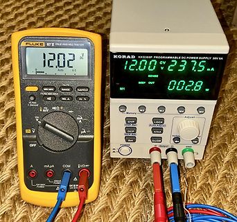
Multimeter und programmierbares Netzteil im Messaufbau
FLUKE 87V TRUE RMS MULTIMETER 12.02 V DC 0 Auto 60 MIN MAX RANGE AutoHOLD Hi Res Second mV Ω + mA µA V V A COM µA 400mA FUSED 10A MAX FUSED CAT III 600V CAT IV 600V KORAD KKG305P PROGRAMMABLE DC POWER SUPPLY 30V 5A 12.00 V 237.5 mA SENSE BEEP OUT 002.8 W M1 M2 M3 M4 M5 Memory OVP OCP OCP-Set OVP-Set LOCK Auto Adjust A/mA Volt/V Set On/Off GND Output
in „Neue Korad Netzteile KKG305D, KKG305P, KKG605P“ · Analoge Elektronik und Schaltungstechnik · · Fotos
-
PDF
RP152N001A-TR-F.pdf
Voltage 600 V (500 IUT=150m A I IUT=50m A V400 IUT=30m A e IUT=10m A a300 o V u200 p r100 D 0 0.5 1.0 1.5 2.0 2.5 3.0 3.5 4.0 Set Output VoltagREG(V) 8) Minimum Operating Voltage 2.0 1.8 ) 1.6 ( I 1.4 V 1.2 g Hatched
in „Such SMD Bauteil im SOT-23-6 Gehäuse mit Markingcode "DJC"“ · Mikrocontroller und Digitale Elektronik ·
-
Datei
playCSV.html
: #1a1a2e; } .btn-play:hover { box-shadow: 0 4px 15px rgba(0, 200, 83, 0.4); } .btn-stop { background: linear-gradient(135deg, #ff1744, #ff5252); color: white; } .btn-stop:hover { box-shadow: 0 4px 15px rgba
in „Welches Audioprogramm kann csv-Dateien abspielen?“ · PC Hard- und Software ·
-
PDF
ad620.pdf
, Voltage Noise, e 72 100 72 100 72 100 nV/√Hz no RTI, 0.1 Hz to 10 Hz G = 1 3.0 3.0 6.0 3.0 6.0 V p-p G = 10 0.55 0.55 0.8 0.55 0.8 V p-p G = 100–1000 0.28 0.28 0.4 0.28 0.4 V p-p Current Noise f = 1 kHz 100 100 100 fA/√Hz 0.1 Hz to 10 Hz 10 10 10 pA p-p REFERENCE INPUT R 20 20 20 k IN IIN VIN+, REF
in „Verständnisproblem Beschaltung Instrumentenverstärker“ · Analoge Elektronik und Schaltungstechnik ·
-
PDF
IMG-RD-232079-21.pdf
casoditensioniinferioriedimodellispecificideipaesidiim- Potenzadiingresso*/** – Potenzadicarica W 600 piego,questidatipossonovariare. – Modalitàcombinata W 1600 *Perunalungadurataconsigliamodinonfarfunzionareil prodottoapiùdi1200W Limitiammissibilidella temperaturaambiente*** °C 0–40 **A1500Wladurataè
in „LiFePo4 über Solar laden - leider mit 230V“ · Analoge Elektronik und Schaltungstechnik ·
-
PDF
Modbus_RTU___Kommunikationshandbuch_fuer_EATON_DC1.pdf
ro – U16 P0-17 Motor Stator Widerstand Meas ro – U16 P0-18 Motor Stator Induktivität Meas ro – U16 P0-19 Motor Rotor Widerstand Meas ro – U16 23 P0-20 Zwischenkreisspannung ro – 600 ≙ 600 V 24 P0-21 Kühlkörpertemperatur
in „ich bitte um Mitt-Hilfe in Sachen RS485; Modbus; Frquenzumrichter; qModMaster“ · Mikrocontroller und Digitale Elektronik ·
-
PDF
PCA9531_5-181573.pdf
(P) (see Figure 8). SDA SCL S P START condition STOP condition mba608 Fig 8. Definition of START and STOP conditions 7.2 System configuration A device generating a message is a ÔtransmitterÕ; a device receiving
in „[V] 3St. SMD 8-bit I2C LED Treiber NXP PCA9531D (SO16)“ · Markt ·
-
PDF
dirt_devil_dd777_1.pdf
charge environ 4 heures Adaptateur secteur Entrée : 100 – 240V ~, Entrée : 100 – 240V ~, 50/60 Hz, 0,5 A 50/60 Hz, 0,8 A Sortie : 25V, 600 mA Sortie : 34V, 600 mA Capacité du bac à poussière 0,6 l Puissance 180W 198W Poids 2,4 kg 2,5 kg Protectiondel’environnementetélimination Si vous voulez jeter l’appareil
in „Suche Zahnriemen für Dirt Devil DD777 Turbobürste (50 Zähne)“ · Markt ·
-
PDF
CD00277537.pdf
4. STM32L15xVx LQFP100 pinout 3 3 0 _ _ T 2 1 0 5 4 D S E E B B O B B B B B D D D D D D D D C C C A A V V P P P P B P P P P P P P P P P P P P P P P P P 0 9 8 7 6 5 4 3 2 1 0 9 8 7 6 5 4 3 2 1 0 9 8 7 6 1 9 9 9 9 9 9 9 9 9 9 8 8 8 8 8 8 8 8 8 8 7 7 7 7 PE2 1 75 VDD_2 PE3 2 74 VSS_2 PE4 3 73 PH2 PE5
in „SPI-Schnittstelle Befehl: SPI_I2S_SendData(spi2, data)“ · Mikrocontroller und Digitale Elektronik ·
-
PDF
D096400_TD.pdf
the capacitors shall meet the same requirement as Endurance. ■ Diagram of Dimensions Sleeve Φd±0.05 a 5 +. P±0.5 P±0.5 D Vent Φ 15min 5min L+a max ψD 5 6.3 8 10 12 13 16 18 22 P 2.0 2.5 3.5 5.0 7.5 10.0 ψd 0.5 0.5 0.6 0.6 0.8 0.8 ( 1.0 ) 1.5 2.0 a 1.5 1.5 1.0 2.0 2.0 2.0 2.0 ( ) : L≧40 ■ Multiplier for
in „im Elko Datenblatt steht "Features: 105℃ 1000 hours"“ · Analoge Elektronik und Schaltungstechnik ·
-
PDF
PHOTOMOS_RELAIS_AQY_1A_400MA_60V.pdf
) AQY216EH(A) Remarks LED forward current IF 50mA LED reverse voltage V R 5 V Input Peak forward current IP 1 A f =100 Hz, Duty factor = 0.1% Power dissipation P in 75mW Load voltage (peak AC) VL 30 V 60 V 350 V 400 V 600 V Continuous load current IL 1 A 0.55 A 0.13 A 0.12 A 0.05 A Output Peak load current Ipeak 3 A 1.5 A 0.4 A 0.3 A 0.15 A 100 ms (1 shot), VL= DC Power dissipation Pout 500mW Total power dissipation
in „Optokoppler 4N35 Fragen“ · Mikrocontroller und Digitale Elektronik ·
-
PDF
504859-da-01-en-PHOTOMOS_RELAIS_AQY_1A_130MA_350V.pdf
) AQY216EH(A) Remarks LED forward current IF 50mA LED reverse voltage V R 5 V Input Peak forward current IP 1 A f =100 Hz, Duty factor = 0.1% Power dissipation P in 75mW Load voltage (peak AC) VL 30 V 60 V 350 V 400 V 600 V Continuous load current IL 1 A 0.55 A 0.13 A 0.12 A 0.05 A Output Peak load current Ipeak 3 A 1.5 A 0.4 A 0.3 A 0.15 A 100 ms (1 shot), VL= DC Power dissipation Pout 500mW Total power dissipation
-
PDF
0900766b811675e1.pdf
) AQY216EH(A) Remarks LED forward current IF 50mA LED reverse voltage V R 5 V Input Peak forward current IP 1 A f =100 Hz, Duty factor = 0.1% Power dissipation P in 75mW Load voltage (peak AC) VL 30 V 60 V 350 V 400 V 600 V Continuous load current IL 1 A 0.55 A 0.13 A 0.12 A 0.05 A Output Peak load current Ipeak 3 A 1.5 A 0.4 A 0.3 A 0.15 A 100 ms (1 shot), VL= DC Power dissipation Pout 500mW Total power dissipation
in „Heizung PT1000 durch pmoddpot ersetzen“ · Mikrocontroller und Digitale Elektronik ·
-
PDF
504846-da-01-en-PHOTOMOS_RELAIS_AQY_1A_400MA_60V.pdf
) AQY216EH(A) Remarks LED forward current IF 50mA LED reverse voltage V R 5 V Input Peak forward current IP 1 A f =100 Hz, Duty factor = 0.1% Power dissipation P in 75mW Load voltage (peak AC) VL 30 V 60 V 350 V 400 V 600 V Continuous load current IL 1 A 0.55 A 0.13 A 0.12 A 0.05 A Output Peak load current Ipeak 3 A 1.5 A 0.4 A 0.3 A 0.15 A 100 ms (1 shot), VL= DC Power dissipation Pout 500mW Total power dissipation
-
PDF
3260.pdf
BIPOLAR SWITCH FUNCTIONAL BLOCK DIAGRAM SUPPLY REG. TO ALL SUBCIRCUITS N T A X C L S M C L L A R A N P O - T GROUND Y A A H W F D T S & L E F F O Dwg. FH-020-4 Suffix Code 'UA' Pinning Suffix Code 'LT' Pinning (SIP) (SOT-89/TO-243AA) X X NC 1 2 3 1 2 3 Y D D Y D LN P N U L N
in „Schaltnetzteil TNY Ersatztyp Kompatibel ?“ · Analoge Elektronik und Schaltungstechnik ·