-
PDF
MC34063A-D.pdf
http://onsemi.com 12 MC34063A, MC33063A, NCV33063A PACKAGE DIMENSIONS PDIP−8 P, P1 SUFFIX CASE 626−05 ISSUE L NOTES: 1. DIMENSION L TO CENTER OF LEAD WHEN FORMED PARALLEL. 8 5 2. PACKAGE CONTOUR OPTIONAL (ROUND OR SQUARE CORNERS). 3. DIMENSIONING AND TOLERANCING PER ANSI −B− Y14.5M, 1982. 1 4 MILLIMETERS
in „5 Volt aus 3,6 Volt mit 34063“ · Analoge Elektronik und Schaltungstechnik ·
-
PDF
MC34063A-D.pdf
http://onsemi.com 12 MC34063A, MC33063A, NCV33063A PACKAGE DIMENSIONS PDIP−8 P, P1 SUFFIX CASE 626−05 ISSUE L NOTES: 1. DIMENSION L TO CENTER OF LEAD WHEN FORMED PARALLEL. 8 5 2. PACKAGE CONTOUR OPTIONAL (ROUND OR SQUARE CORNERS). 3. DIMENSIONING AND TOLERANCING PER ANSI −B− Y14.5M, 1982. 1 4 MILLIMETERS
in „MC34063 Strombegrenzung“ · Mikrocontroller und Digitale Elektronik ·
-
PDF
MT6252_Design_Notice.pdf
by Vbat_off V_FULL2FAST_THR and in talking mode >4.05V and Vbat_off ES mode V_PROTECT_L modealking >4.05V and OW_LI in talking PMU CV(4.2V) = 1, Vbat_off > 3.4V mode V_PRE2FAST_THRES detected rate = 6 times 1. Complete msg Fast (CC) 2. Wait 90 seconds charge
in „Amparos GPS Tacker - Pollin Schnäppchen“ · Mikrocontroller und Digitale Elektronik ·
-
Datei
test_O2.asm
test.elf: file format elf32-littlearm SYMBOL TABLE: 08000000 l d .isr_vector 00000000 .isr_vector 08000188 l d .text 00000000 .text 08000338 l d .ARM 00000000 .ARM 08000340 l d .init_array 00000000 .init_array 08000344 l d .fini_array 00000000 .fini_array 20000000 l d .bss 00000000 .bss 2000001c l d ._user_heap_stack 00000000 ._user_heap_stack 00000000 l d .ARM.attributes 00000000 .ARM.attributes 00000000 l d .comment 00000000 .comment 00000000 l d .debug_frame
in „C++ Exceptions mit gcc-arm-none-eabi“ · Mikrocontroller und Digitale Elektronik ·
-
PDF
lm324_DeepL_de.pdf
[1] 7 8 SYMM BEISPIEL FÜR FLÄCHENMUSTER LÖTFREIE MASKE DEFINIERTER MASSSTAB: 5X .002 MAX (.063) [0.05] [1.6] METALL RUNDUM ( .063) FNUNGSKENÖF [1.6] METAL L LÖTTERMASKE .002 MAX (R.002 ) TYP ERÖFFNUNG [0.05] [0.05] RUNDUM DETAIL A DETAIL B SKALA: 15X 13X, MASSSTAB: 15X 4214771/A 05/2017 www.ti.com BODENMUSTERDATEN
in „gutes Übersetzungsprogramm für Datenblätter gesucht“ · Offtopic ·
-
PDF
BUV48AFI_STMicroelectronics.pdf
DIM. MIN. TYP. MAX. MIN. TYP. MAX. A 4.7 4.9 0.185 0.193 C 1.17 1.37 0.046 0.054 D 2.5 0.098 E 0.5 0.78 0.019 0.030 F 1.1 1.3 0.043 0.051 G 10.8 11.1 0.425 0.437 H 14.7 15.2 0.578 0.598 L2 – 16.2 – 0.637 L3 18 0.708 L5 3.95 4.15 0.155 0.163 L6 31 1.220 R – 12.2 – 0.480 Ø 4 4.1 0.157 0.161 E A C D L6 L5
-
Datei
oled.cpp
0x02, // f 0x00, 0x18, 0xA4, 0xA4, 0xA4, 0x7C, // g 0x00, 0x7F, 0x08, 0x04, 0x04, 0x78, // h 0x00, 0x00, 0x44, 0x7D, 0x40, 0x00, // i 0x00, 0x40, 0x80, 0x84, 0x7D, 0x00, // j 0x00, 0x7F, 0x10, 0x28, 0x44, 0x00, // k 0x00, 0x00, 0x41, 0x7F, 0x40, 0x00, // l 0x00, 0x7C, 0x04, 0x18, 0x04, 0x78, // m 0x00, 0x7C, 0x08, 0x04, 0x04, 0x78, // n 0x00, 0x38, 0x44, 0x44, 0x44, 0x38, // o 0x00, 0xFC, 0x24, 0x24, 0x24, 0x18, // p 0x00, 0x18, 0x24, 0x24, 0x18, 0xFC, // q 0x00, 0x7C, 0x08, 0x04, 0x04,
in „Zeichnen eines Punktes mit LCD_Plot_Point“ · Mikrocontroller und Digitale Elektronik ·
-
Datei
oled.cpp
0x02, // f 0x00, 0x18, 0xA4, 0xA4, 0xA4, 0x7C, // g 0x00, 0x7F, 0x08, 0x04, 0x04, 0x78, // h 0x00, 0x00, 0x44, 0x7D, 0x40, 0x00, // i 0x00, 0x40, 0x80, 0x84, 0x7D, 0x00, // j 0x00, 0x7F, 0x10, 0x28, 0x44, 0x00, // k 0x00, 0x00, 0x41, 0x7F, 0x40, 0x00, // l 0x00, 0x7C, 0x04, 0x18, 0x04, 0x78, // m 0x00, 0x7C, 0x08, 0x04, 0x04, 0x78, // n 0x00, 0x38, 0x44, 0x44, 0x44, 0x38, // o 0x00, 0xFC, 0x24, 0x24, 0x24, 0x18, // p 0x00, 0x18, 0x24, 0x24, 0x18, 0xFC, // q 0x00, 0x7C, 0x08, 0x04, 0x04,
in „Arduino Bibliothek - Methoden bzw. Funktionen en Detail erklärt - gesucht“ · Mikrocontroller und Digitale Elektronik ·
-
Datei
oled.cpp
0x02, // f 0x00, 0x18, 0xA4, 0xA4, 0xA4, 0x7C, // g 0x00, 0x7F, 0x08, 0x04, 0x04, 0x78, // h 0x00, 0x00, 0x44, 0x7D, 0x40, 0x00, // i 0x00, 0x40, 0x80, 0x84, 0x7D, 0x00, // j 0x00, 0x7F, 0x10, 0x28, 0x44, 0x00, // k 0x00, 0x00, 0x41, 0x7F, 0x40, 0x00, // l 0x00, 0x7C, 0x04, 0x18, 0x04, 0x78, // m 0x00, 0x7C, 0x08, 0x04, 0x04, 0x78, // n 0x00, 0x38, 0x44, 0x44, 0x44, 0x38, // o 0x00, 0xFC, 0x24, 0x24, 0x24, 0x18, // p 0x00, 0x18, 0x24, 0x24, 0x18, 0xFC, // q 0x00, 0x7C, 0x08, 0x04, 0x04,
in „Display was auf Knopfdruck Datum anzeigt“ · Mikrocontroller und Digitale Elektronik ·
-
Datei
lcd.cpp
0x02, // f 0x00, 0x18, 0xA4, 0xA4, 0xA4, 0x7C, // g 0x00, 0x7F, 0x08, 0x04, 0x04, 0x78, // h 0x00, 0x00, 0x44, 0x7D, 0x40, 0x00, // i 0x00, 0x40, 0x80, 0x84, 0x7D, 0x00, // j 0x00, 0x7F, 0x10, 0x28, 0x44, 0x00, // k 0x00, 0x00, 0x41, 0x7F, 0x40, 0x00, // l 0x00, 0x7C, 0x04, 0x18, 0x04, 0x78, // m 0x00, 0x7C, 0x08, 0x04, 0x04, 0x78, // n 0x00, 0x38, 0x44, 0x44, 0x44, 0x38, // o 0x00, 0xFC, 0x24, 0x24, 0x24, 0x18, // p 0x00, 0x18, 0x24, 0x24, 0x18, 0xFC, // q 0x00, 0x7C, 0x08, 0x04, 0x04,
in „SSD1306/1309 Library zum Darstellen von Text auf OLED Displays“ · Projekte & Code ·
-
Datei
oled.cpp
0x02, // f 0x00, 0x18, 0xA4, 0xA4, 0xA4, 0x7C, // g 0x00, 0x7F, 0x08, 0x04, 0x04, 0x78, // h 0x00, 0x00, 0x44, 0x7D, 0x40, 0x00, // i 0x00, 0x40, 0x80, 0x84, 0x7D, 0x00, // j 0x00, 0x7F, 0x10, 0x28, 0x44, 0x00, // k 0x00, 0x00, 0x41, 0x7F, 0x40, 0x00, // l 0x00, 0x7C, 0x04, 0x18, 0x04, 0x78, // m 0x00, 0x7C, 0x08, 0x04, 0x04, 0x78, // n 0x00, 0x38, 0x44, 0x44, 0x44, 0x38, // o 0x00, 0xFC, 0x24, 0x24, 0x24, 0x18, // p 0x00, 0x18, 0x24, 0x24, 0x18, 0xFC, // q 0x00, 0x7C, 0x08, 0x04, 0x04,
in „OLED Display mit I2C Bus am Slave betreiben“ · Mikrocontroller und Digitale Elektronik ·
-
PDF
RTC-4553.pdf
V 2 WR 13 SOUT Operatingtemperature TOPR Nocondensation -30 — +70 ˚C 3 SIN 12 CS 1 4 SCK 11 CS 0 5 L1 10 L5 6 L2 9 L4 Frequency characteristics 7 L3 8 VDD Item Symbol Condition Range Unit AA 5±5 L1 to L5 are test pin. Do not connect them to any terminals. Ta=+25 °C, Frequency tolerance Df/fo V D=5 V
-
PDF
IMC0805ER1R8J01_VISHS83958_1-2566393_unpw.pdf
DIMENSIONS TAPE DIMENSIONS RECOMMENDED PATTERN 0.08 ±0.02 [2.0 ±0.5] [2.0 ± 0.5] 0.07 ±0.002 [1.75 ±0.05] B 0.14 ±0.002.158 ±0.0.08 ±0.002 0.1 ±0.002 0.51 ±0.02 [3.5 ±0.05]4.0 ±0.1[2.0 ±0.05][0.3 ±0.05] A Ø [13.0 ±0.5] C 0.83 ±0.03 Ø [21.0 ±0.8] T 7.0 ±0.08 0.55 ± 0.04 0.315 ±0.008 A ±0.004 ±0.002 [178.0 ±2.0] [14.0 ± 1.0] [8.0 ±0.2] [±0.1] [±0.05] 0[4.0 ±0.1]4 B[±0.1]4 MODEL UNITS PER REEL MODEL A B T MODEL A B C 0.055 0.091 0.055 0.047 0.102 0.047 IMC-0805-01 2000 IMC-0805-01 IMC-0805-01 [1.4] [2.3] [1.4] [1.20] [2.6] [1.20] www.vishay.com For
in „Pollin SMD-Induktivitäten identifizieren“ · Analoge Elektronik und Schaltungstechnik ·
-
PDF
rfax.pdf
WATERS OF THE NORTH PACIFIC. L' - 1:05,000,00049N 140E 49N 151E, 41N 140E 40N149E X - 1: 6,000,000 46N 107E, 43N 160E, 18N 118E, 17N147E (INFORMATION DATED 122 Jan 2014) http://www.jma-net.go.jp/common/177jmh/JMH-ENG.pdf PEVEK, CHUKOTKA
-
PDF
schematics.pdf
D[0:15] A1 J14A1 D0M9 D0 U35 A2 K14A2 D1N9 D1 PJ0_MDC C7MDC GPIO/UART0_TX/DMAR0 M1 PF0_UART0_TX A3 L14A3 D2P9 D2 A4 J13 M8 D3 PJ1_MDIO B7MDIO GPIO/UART0_RX/DMAR1/TACI1 L1 PF1_UART0_RX A4 D3 B11 L2 A5 K13 N8 D4 PJ2_SCL SCL GPIO/UART1_TX/TMR7 PF2_PB1 A5 D4 C11 L3 A6 L13 P8 D5 PJ3_SDA SDA GPIO/UART1_RX
in „Versorgung“ · Digitale Signalverarbeitung / DSP / Machine Learning ·
-
PDF
CD4538.pdf
2Q 2Cx 2RxCx 15 14 GND = 8 VCC V = 16 CC 2Cx 2Rx TRUTH TABLE R2 INPUTS OUTPUTS CL R1 Q R A B Q Q CL L X X L H p D n X H X L H CL CL X X L L H Q p CL H L ↓ n p H ↑ H CL n R1 CL H = High Level, L = Low Level, ↑ = Transition from Low to High, ↓ = Transition from High to Low,One High Level Pulse, One Low
in „Unterschied CD4528 zu CD4538 ?“ · Mikrocontroller und Digitale Elektronik ·
-
PDF
256kbit_segor_70ns.pdf
L 0.79 1.27 0.031 0.050 α 0° 8° 0° 8° N 28 28 16/22 M68AF031A Figure 17. PDIP28 - 28 pin Plastic DIP, 600 mils width, Package Outline A2 A A1 L α B1 B e1 C eA D2 eB D S N E1 E 1 PDIP Note: Drawing is not
in „AVR Synthesizer Konzept“ · Mikrocontroller und Digitale Elektronik ·
-
PDF
MC34063A-D.pdf
751 8 8 8 3x063AP1 33063AVP AWL AWL 3x063 YYWW YYWW ALYWA 1 1 1 x = 3 or 4 A = Assembly Location WL, L = Wafer Lot YY, Y = Year WW, W = Work Week http://onsemi.com 11 MC34063A, MC33063A, NCV33063A PACKAGE DIMENSIONS PDIP−8 P, P1 SUFFIX PLASTIC PACKAGE CASE 626−05 ISSUE L NOTES: 1. DIMENSION L TO CENTER
in „Ersatz für 7805 gesucht“ · Mikrocontroller und Digitale Elektronik ·
-
Datei
font.h
/* 47 71 G */ 40, /* 48 72 H */ 41, /* 49 73 I */ 42, /* 4A 74 J */ 43, /* 4B 75 K */ 44, /* 4C 76 L */ 45, /* 4D 77 M */ 46, /* 4E 78 N */ 47, /* 4F 79 O */ 48, /* 50 80 P */ 49, /* 51 81 Q */ 50, /* 52 82 R */ 51, /* 53 83 S */ 52, /* 54 84 T */ 53, /* 55 85 U */ 54, /* 56 86 V */ 55, /* 57 87 W *
in „Frage zur Optimierung Display Text mit Font“ · Mikrocontroller und Digitale Elektronik ·
-
PDF
LM2595.pdf
PE-53827-S DO5022P-224 L28 150 1.20 67144120 67144500 RL-5471-3 — PE-53828 PE-53828-S DO5022P-154 L29 100 1.47 67144130 67144510 RL-5471-4 — PE-53829 PE-53829-S DO5022P-104 L30 68 1.78 67144140 67144520 RL-5471-5 — PE-53830
in „Schaltregler 9-18V input 14-V output“ · Analoge Elektronik und Schaltungstechnik ·
-
PDF
LM2595.pdf
PE-53827-S DO5022P-224 L28 150 1.20 67144120 67144500 RL-5471-3 — PE-53828 PE-53828-S DO5022P-154 L29 100 1.47 67144130 67144510 RL-5471-4 — PE-53829 PE-53829-S DO5022P-104 L30 68 1.78 67144140 67144520 RL-5471-5 — PE-53830
in „5 Volt 1A fürs auto passiv gekühlt gesucht“ · Analoge Elektronik und Schaltungstechnik ·
-
PDF
ads8684.pdf
M: x SDO Gain Error versus Temperature AIN_4P OVP PGA 2nd-OrdeADC p 16-bit AIN_4GND OVP LPF Driver l SAR ADC DAISY 0.05 1 M: VB4 u ----- ± 2.5*VREF M -----± 1.25*V REF AIN_5P 1 M:OVP REFSEL 0.03 ----- ± 0.625*REF AIN_5GND PGA 2nLPFrdeDriver Oscillator ------ +2.5*REF 6 1 M:OVP RST / PD ------+1.25*REF
in „Problem mit der SPI Datenübertragung zwischen einem Arduino Portenta H7 und einem ADS8684 (ADC)“ · Mikrocontroller und Digitale Elektronik ·
-
PDF
74HCT00.pdf
2.79 0.090 0.110 G 0.4 0.55 0.016 0.022 H 1.17 1.52 0.046 0.060 L 0.22 0.31 0.009 0.012 M 1.52 2.54 0.060 0.100 N 10.3 0.406 P 7.8 8.05 0.307 0.317 Q 5.08 0.200 P053C 6/9 M54/M74HCT00 SO14 MECHANICAL DATA mm inch DIM. MIN. TYP. MAX. MIN. TYP. MAX. A 1.75 0.068 a1 0.1
in „Pegelwandler 3.3v -> 5v“ · Mikrocontroller und Digitale Elektronik ·
-
PDF
Weidezaun_S03_4093.pdf
-2,5V 0,49K/W N-Ch 0,35€ mm2 AWG EinadrigMehradriginadrig l 4 L L H 4 2,9V 11AO3400 30V 5,8A 28/33mR 630pF Vgs_th=1,05V 0,14€/10 Mark A09T empfindliche Tiere z.B. Hunde 2600Vs Impulsenergie 0,1J, Ladeenergie 0,12J 0,34 22 8A 6A 6A i 9 L H H 13NAND 1,9V DVM_DPM951
in „Weidezaun gegen Schnecken mit Netztrafo und Rohr DN160 für Hobbygärtner“ · Projekte & Code ·
-
PDF
MC10EP31-D.PDF
MAX A 2.90 3.10 0.114 0.122 C B 2.90 3.10 0.114 0.122 C 0.80 1.10 0.031 0.043 0.10 (0.004) −W− D 0.05 0.15 0.002 0.006 −T− SEATING D F 0.40 0.70 0.016 0.028 PLANE G G 0.65 BSC 0.026 BSC K 0.25 0.40 0.010 0.016 DETAIL E L 4.90 BSC 0.193 BSC M 0_ 6_ 0_ 6_ www.onsemi.com 10 MC10EP31, MC100EP31 PACKAGE DIMENSIONS
in „Rechtecksignal mit Anstiegszeit < 1 ns für Oszi- und Tastkopf-Tests“ · HF, Funk und Felder ·
-
PDF
Dissertation.pdf
0,4 mg/L freies Chlor min. 0,05 mg/L freies Chlor max. 0,3 mg/L freies Chlor Natriumhypochlorit 1,2 mg/L freies Chlor min. 0,1 mg/L freies Chlor Ozon 10 mg/L O 3 max. 0,05 mg/L O 3 Desinfektionsverfahren: ¾ UV-Bestrahlung
in „UVC Wasserentkeimung mit Led?“ · Analoge Elektronik und Schaltungstechnik ·
-
 Bild
Ausschnitt eines Schaltplans
UHF L04a C05 15 R018 2,2k C018 820 C017 2,7 R019 1,8k UHF-VHF-Abstimmung 235V 2Vss +A 215V 200mVss +B 215V (6Vss) 200mVss +C 220V ca 110W R69 2,2M C70 0,22uF D2 BY 127 R70 6,8 R77/30/5,5W 150 C72 10n D1 280V R78 470 C81 200uF C82 50uF Messwert bei arbeitendem Bildkippgenerator gemessen wenn der vertikal gen. works PL504 PY88 PCF802 PCL905 Bildröhre PCL86 R74 68 R75 68 +D 25V C73 0,1uF C74 2,2uF C75 2,2uF C84
in „PY88 röhre was ist Rs?“ · Analoge Elektronik und Schaltungstechnik · · Fotos

-
 Bild
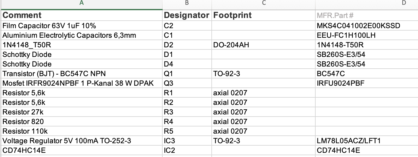
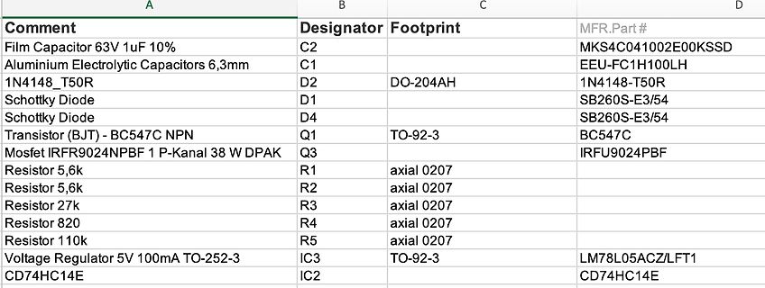
Bauteilliste oder BOM Tabelle
Resistor 820 R4 axial 0207 Resistor 110k R5 axial 0207 Voltage Regulator 5V 100mA TO-252-3 IC3 TO-92-3 LM78L05ACZ/LFT1 CD74HC14E IC2 CD74HC14E
in „CD74HC14M Schmitt-Trigger Schaltung funktioniert nicht“ · Mikrocontroller und Digitale Elektronik · · Screenshots
-
PDF
china_dimmer.pdf
X1-1 X1-3 IC13 D 78M05C1 V D D D11 1 VI VO 3 V V X1-2 M7 X1-4 GND 8 1 4 +C15 1 k n GND C12 R 0 l 1 k 10uF/25V 2 R 1 R 4 QR11 100nF 3 5 IC12B FDB6670AL 4 7 1 6 1 1 LM358D GND GND GND GND k 1 0 R D D D D V IC11 V 6 8 GND
in „0-100% PWM mit NE555“ · Analoge Elektronik und Schaltungstechnik ·
-
PDF
Energmix_Schematic.pdf
X1-1 X1-3 IC13 D 78M05C1 D D D D11 1 3 V D D VI VO V V X1-2 M7 GND X1-4 4 8 2 9 +C15 R 0 l 5 7 GND C12 1 k R 4 10uF/25V 2 R 1 QR11 100nF 4 3 5 IC12B FDB6670AL 1 7 6 1 1 LM358D GND GND GND GND k R 0 D D V V IC11 GND GND
in „Schaltplan für Led Dimmer gesucht“ · Analoge Elektronik und Schaltungstechnik ·
-
PDF
ATtiny841_Datasheet.pdf
bit registers. See “Accessing 16-bit Registers” on page 108. ATtiny441/841 [DATASHEET] 117 8495H–AVR–05/2014 12.12.9 ICRnH and ICRnL – Input Capture Register n Bit 7 6 5 4 3 2 1 0 0x25 (0x45) ICR1[15:8] ICR1H 0x24 (0x44) ICR1[7:0] ICR1L Read/Write R/W R/W R/W R/W R/W R/W R/W R/W Initial Value 0 0 0 0 0
in „TOCPMSA1 und TOCPMCOE Verhalten beim Attiny 841“ · Mikrocontroller und Digitale Elektronik ·
-
PDF
ATtiny441_841.pdf
bit registers. See “Accessing 16-bit Registers” on page 108. ATtiny441/841 [DATASHEET] 117 8495H–AVR–05/2014 12.12.9 ICRnH and ICRnL – Input Capture Register n Bit 7 6 5 4 3 2 1 0 0x25 (0x45) ICR1[15:8] ICR1H 0x24 (0x44) ICR1[7:0] ICR1L Read/Write R/W R/W R/W R/W R/W R/W R/W R/W Initial Value 0 0 0 0 0
in „Suche nach ATtiny mit ADC und Gain > 20x“ · Mikrocontroller und Digitale Elektronik ·
-
PDF
ATtiny841_Datasheet.pdf
bit registers. See “Accessing 16-bit Registers” on page 108. ATtiny441/841 [DATASHEET] 117 8495H–AVR–05/2014 12.12.9 ICRnH and ICRnL – Input Capture Register n Bit 7 6 5 4 3 2 1 0 0x25 (0x45) ICR1[15:8] ICR1H 0x24 (0x44) ICR1[7:0] ICR1L Read/Write R/W R/W R/W R/W R/W R/W R/W R/W Initial Value 0 0 0 0 0
in „sleep und Interrupt“ · Mikrocontroller und Digitale Elektronik ·
-
PDF
ATtiny841_Datasheet.pdf
bit registers. See “Accessing 16-bit Registers” on page 108. ATtiny441/841 [DATASHEET] 117 8495H–AVR–05/2014 12.12.9 ICRnH and ICRnL – Input Capture Register n Bit 7 6 5 4 3 2 1 0 0x25 (0x45) ICR1[15:8] ICR1H 0x24 (0x44) ICR1[7:0] ICR1L Read/Write R/W R/W R/W R/W R/W R/W R/W R/W Initial Value 0 0 0 0 0
in „Takt-Vorskalierungsregister beim Attiny841“ · Mikrocontroller und Digitale Elektronik ·
-
PDF
3B036723d01.pdf
MC68HC05B6 11-14 12 MECHANICAL DATA 12.1 MC68HC05B6 pin configurations 12.1.1 52-pin plastic leaded chip carrier (PLCC) 5 6 7 L A A A P P2 E L 5 6 7 M M O L I 0 1 2 V N P P P T C CTD T S R P P P C 7 6 5 4 3 2
in „unbekanntes Touchpad, wie anschliessen und verwenden?“ · Mikrocontroller und Digitale Elektronik ·
-
PDF
pkg.pdf
B S PARTING LINE TOP VIEW SEE DETAIL "A" END VIEW S Y COMMON B DIMENSIONS 2 NX R R1 O GAUGE PLANE L MIN. NOM. MAX. A -- -- 2.0 OC A A 1 0.05 -- -- A 2 1.65 1.75 1.85 0.25 BSC b 0.22 - 0.38 A b 1 0.22 0.30 0.33 L 4 c 0.09 -- 0.25 SEATING PLANE c 1 0.09 0.15 0.21 L1 D 9.90 10.20 10.50 DETAIL 'A' E1 5.00
in „Pinabstand aus dem Datenblatt ermitteln, ich blicke nicht durch“ · Mikrocontroller und Digitale Elektronik ·
-
PDF
Instruction_Card_Z80.pdf
links zw. Akku und (HL) RRD ED67 * * 0 P 0 - Rotiere Ziffern rechts zw. Akku und (HL) A B C D E H L (HL) (IX+d) (IY+d) RLC CB07 CB00 CB01 CB02 CB03 CB04 CB05 CB06 DDCB..06 FDCB..06 RRC CB0F CB08 CB09 CB0A CB0B CB0C CB0D CB0E DDCB..0E FDCB..0E RL CB17 CB10 CB11 CB12 CB13 CB14 CB15 CB16 DDCB..16 FDCB
in „Retro Fieber: Z80 oder 68000 ?“ · Mikrocontroller und Digitale Elektronik ·
-
PDF
supercap_manual.pdf
please read "Precautions" and other safety precautions listed in the printed version catalog. 2017.05.17 9565SCGVOL01E1705H1 Resistive discharge characteristics (Backup time capability) FG0H105ZF at 25 ˚C [Charging: 5 V, 0 Ω, 24 h] 6.0 5.0 c d ( 4.0 g l v3.0 l i r 2.0 e 50kΩ 100kΩ250kΩ500kΩ 1MΩ2.5MΩ
in „Super cap - .1F 5.5V TOKIN“ · Analoge Elektronik und Schaltungstechnik ·
-
PDF
ks0066u.pdf
8-bit bus mode. Table 3. Various kinds of Operations according to RS and R/W bits RS R/W Operation L L Instruction Write operation (MPU writes Instruction code into IR) L H Read Busy flag(DB7) and address counter (DB0 to DB6) H L Data Write operation (MPU writes data into DR) H H Data Read operation
in „4x40 LCD Display ohne HD Controller ansteuern.“ · Mikrocontroller und Digitale Elektronik ·
-
PDF
KS0066_Samsung_553815_1.pdf
8-bit bus mode. Table 3. Various kinds of Operations according to RS and R/W bits RS R/W Operation L L Instruction Write operation (MPU writes Instruction code into IR) L H Read Busy flag(DB7) and address counter (DB0 to DB6) H L Data Write operation (MPU writes data into DR) H H Data Read operation
in „LCD unter Bascom, welches?“ · Mikrocontroller und Digitale Elektronik ·
-
PDF
KS0066.pdf
8-bit bus mode. Table 3. Various kinds of Operations according to RS and R/W bits RS R/W Operation L L Instruction Write operation (MPU writes Instruction code into IR) L H Read Busy flag(DB7) and address counter (DB0 to DB6) H L Data Write operation (MPU writes data into DR) H H Data Read operation
in „[ AVR ] Probleme mit LCD-Display (KS0066)“ · Mikrocontroller und Digitale Elektronik ·
-
PDF
ks0066u.pdf
8-bit bus mode. Table 3. Various kinds of Operations according to RS and R/W bits RS R/W Operation L L Instruction Write operation (MPU writes Instruction code into IR) L H Read Busy flag(DB7) and address counter (DB0 to DB6) H L Data Write operation (MPU writes data into DR) H H Data Read operation
in „LCD zeigt was falsches nach Reset; ATmega8 avrgcc“ · Mikrocontroller und Digitale Elektronik ·
-
PDF
ks0066.pdf
8-bit bus mode. Table 3. Various kinds of Operations according to RS and R/W bits RS R/W Operation L L Instruction Write operation (MPU writes Instruction code into IR) L H Read Busy flag(DB7) and address counter (DB0 to DB6) H L Data Write operation (MPU writes data into DR) H H Data Read operation
in „LCD nur 8 von 16 zeichen lassen sich beschreiben“ · Mikrocontroller und Digitale Elektronik ·
-
PDF
LCD-20x2-ganz.pdf
8-bit bus mode. Table 3. Various kinds of Operations according to RS and R/W bits RS R/W Operation L L Instruction Write operation (MPU writes Instruction code into IR) L H Read Busy flag(DB7) and address counter (DB0 to DB6) H L Data Write operation (MPU writes data into DR) H H Data Read operation
in „Init Problem mit KS0066 (Conrad)“ · Mikrocontroller und Digitale Elektronik ·
-
PDF
ks0066.pdf
8-bit bus mode. Table 3. Various kinds of Operations according to RS and R/W bits RS R/W Operation L L Instruction Write operation (MPU writes Instruction code into IR) L H Read Busy flag(DB7) and address counter (DB0 to DB6) H L Data Write operation (MPU writes data into DR) H H Data Read operation
in „Reloadwertberechnung C167“ · Mikrocontroller und Digitale Elektronik ·
-
PDF
553815_1.pdf
8-bit bus mode. Table 3. Various kinds of Operations according to RS and R/W bits RS R/W Operation L L Instruction Write operation (MPU writes Instruction code into IR) L H Read Busy flag(DB7) and address counter (DB0 to DB6) H L Data Write operation (MPU writes data into DR) H H Data Read operation
in „Probleme mit 2ter Zeile bei KS0066 LCD: Lösung“ · Mikrocontroller und Digitale Elektronik ·
-
PDF
ks0066u.pdf
8-bit bus mode. Table 3. Various kinds of Operations according to RS and R/W bits RS R/W Operation L L Instruction Write operation (MPU writes Instruction code into IR) L H Read Busy flag(DB7) and address counter (DB0 to DB6) H L Data Write operation (MPU writes data into DR) H H Data Read operation
in „LCD einfach nur ansteuern.“ · Mikrocontroller und Digitale Elektronik ·
-
PDF
KS0066U.pdf
8-bit bus mode. Table 3. Various kinds of Operations according to RS and R/W bits RS R/W Operation L L Instruction Write operation (MPU writes Instruction code into IR) L H Read Busy flag(DB7) and address counter (DB0 to DB6) H L Data Write operation (MPU writes data into DR) H H Data Read operation
-
PDF
datasheet.pdf
8-bit bus mode. Table 3. Various kinds of Operations according to RS and R/W bits RS R/W Operation L L Instruction Write operation (MPU writes Instruction code into IR) L H Read Busy flag(DB7) and address counter (DB0 to DB6) H L Data Write operation (MPU writes data into DR) H H Data Read operation
in „KS0066: datasheet“ · Mikrocontroller und Digitale Elektronik ·
-
PDF
ks0066.pdf
8-bit bus mode. Table 3. Various kinds of Operations according to RS and R/W bits RS R/W Operation L L Instruction Write operation (MPU writes Instruction code into IR) L H Read Busy flag(DB7) and address counter (DB0 to DB6) H L Data Write operation (MPU writes data into DR) H H Data Read operation
in „LCD KS0066 an 16F871“ · Mikrocontroller und Digitale Elektronik ·