-
PDF
DSPIC33EP512GM710_datasheet.pdf
SPI3EIP0 — U4TXIP2 U4TXIP1 U4TXIP0 — U4RXIP2 U4RXIP1 U4RXIP0 0000 IPC23 086E — PGC2IP2 PGC2IP1 PGC2IP0 — PWM1IP2 PWM1IP1 PWM1IP0 — — — — — — — — 4400 d IPC24 0870 — PWM6IP2 PWM6IP1 PWM6IP0 — PWM5IP2 PWM5IP1 PWM5IP0 — PWM4IP2 PWM4IP1 PWM4IP0 — PWM3IP2 PWM3IP1 PWM3IP0 4444 s IPC35 0886 — JTAGIP2 JTAGIP1 JTAGIP0
in „Probleme mit SRAM 23LCV1024“ · Mikrocontroller und Digitale Elektronik ·
-
PDF
ZXLD1366.pdf
1 A RLX LX switch ‘On’ resistance @ ILX = 1A 0.50 0.75 Ω ILX(leak) LX switch leakage current 5 µA PWM frequency < 300Hz PWM D PWM(LF) Duty cycle range of PWM signal applied to ADJ pin amplitude = VREF 0.001 1.000 V during low frequency PWM dimming mode Measured on ADJ pin Brightness control range 1000
in „Spannungsteiler zwischen Arduino und KSQ“ · Mikrocontroller und Digitale Elektronik ·
-
PDF
AS5311_DS000200_2-00.pdf
1.13 15 - 32 AS5311 Datasheet - Detailed Description Figure 8. PWM Output Signal Position PW MIN 0µm (Pos 0) 1µs 4098µs PW MAX 1999.5µm (Pos 4095) 4097µs 1/fPWM 7.7 3.3V / 5V Operation The AS5311 operates either at 3.3V ±10% or at 5V ±10%. This is made possible by
in „Allgoryhmus um Störungen an Inkrementalgeber zu eleminieren“ · Mikrocontroller und Digitale Elektronik ·
-
PDF
2097320.pdf
1 A RLX LX switch ‘On’ resistance @ ILX = 1A 0.50 0.75 Ω ILX(leak) LX switch leakage current 5 µA PWM frequency < 300Hz PWM D PWM(LF) Duty cycle range of PWM signal applied to ADJ pin amplitude = VREF 0.001 1.000 V during low frequency PWM dimming mode Measured on ADJ pin Brightness control range 1000
in „ZXLD1366 Beschaltung ADJ Pin“ · Analoge Elektronik und Schaltungstechnik ·
-
PDF
Loetstation_extracted.pdf
sind unbestritten. Wie in [1] jedoch aus arbeitet hatte, wollte ich anschließend mit moduliertes (PWM-)Signal an den Leis führlich dargelegt, ist es für den Hobby nichts anderem mehr löten. tungsteil zur Steuerung der Heizung aus. bastler aber grundsätzlich kein Problem, Problematisch für die Hobbykasse
in „Thermoelement im Weller WMRP.“ · Mikrocontroller und Digitale Elektronik ·
-
Datei
Lauli1.asm
; r1 Zähler für Anzahl Ausgabebytes in Tabelle ; r2 immer Null, hier zum Ausschalten der LEDs zur PWM-Dunkelphase ; r16 PWM-Treppenzähler ; r17 Helligkeitszähler für PWM ; r18 Dimmrichtung ; r28/r29 Pausenzähler (yl/yh) ; r30/r31 Pointer auf Tabelle (zl/zh) .include"m8def.inc" ;Hier können einige Einstellungen
in „Code von ganz besonderem Lauflicht vereinfachen“ · Mikrocontroller und Digitale Elektronik ·
-
Datei
PWM_PA0_Uvergleich-3.9khz.asm
;ausgangsspannungsregelung nach stepdown ;pwm an atmega16 für 3,906 khz ;bei 4mhz taktfrequenz ;mit timer0 im fast pwm mode, 8 bit aufloesung ;pwm-signal liegt auf pb3 oc0 ;11.2.12 .include "m16def.inc" jmp start ;führe reset aus ;.def v_panel
in „Hilfe Ladereglung Atmega16 Assembler“ · Mikrocontroller und Digitale Elektronik ·
-
PDF
BLDC_01a.pdf
ACPL-790/mil-300 ADC_0 12Bit, 1Ch, Iso-Amp 24..300V DC SN74ALVC244 6x IRFP450/ 500V 14A SOIC-20 PWM_0 6 PWM_1 O ASC710/SOIC16 PWM_2 / Hall, 120kHz 4 PWM_3 P L PWM_4 P A PWM_5 6 AS5048A/TSSOP14 DC 14Bit, 3/4-wire-SPI DC LTC1408/QFN-32 DC 12Bit, 6 Ch, 600ksps DC ADuM1402/SOIC-W DC DC 41Ch, digital Isolator
in „SVPWM mit LPC1769“ · Mikrocontroller und Digitale Elektronik ·
-
PDF
BLDC_01a.pdf
ACPL-790/mil-300 ADC_0 12Bit, 1Ch, Iso-Amp 24..300V DC SN74ALVC244 6x IRFP450/ 500V 14A SOIC-20 PWM_0 6 PWM_1 O ASC710/SOIC16 PWM_2 / Hall, 120kHz 4 PWM_3 P L PWM_4 P A PWM_5 6 AS5048A/TSSOP14 DC 14Bit, 3/4-wire-SPI DC LTC1408/QFN-32 DC 12Bit, 6 Ch, 600ksps DC ADuM1402/SOIC-W DC DC 41Ch, digital Isolator
in „Brushless DC Servo - Ansteuerung mit Eval-Boards (Konzept)“ · Mikrocontroller und Digitale Elektronik ·
-
PDF
Atmel-8209-8-bit_AVR_ATmega16M1-32M1-64M1_Datasheet_1_.pdf
correct PWM mode, the compare units allow generation of PWM waveforms on the OC1x pins. Setting the COM1x[1:0] bits to 0x2 will produce a non-inverted PWM and an inverted PWM output can be generated by setting
in „Externer Interrupt“ · Mikrocontroller und Digitale Elektronik ·
-
PDF
UM10736.pdf
and 0x1C02 4060 (SCT3)) bit description”. • Fixed typographical errors in Chapter 15 “Large SCTimer/PWM (SCTimer0/PWM, SCTimer1/PWM)” and Chapter 16 “Small SCTimer/PWM (SCTimer2/PWM, SCTimer3/PWM)” . • Changed SCTIPU_ABORT to SCTIPU_ABORT0, SCTIPU_ABORT1, and SCTIPU_ABORT2. See Table 127 , Table 128,
in „LPC1549 USB Virtual COM-Port“ · Mikrocontroller und Digitale Elektronik ·
-
Datei
Atmega8-V5_Flacker1_Poti.bas
BCD-B Config Portd.7 = Output 'Pin 13 BCD-C Config Portb.0 = Output 'Pin 14 BCD-D Config Timer1 = Pwm , Pwm = 8 , Compare A Pwm = Clear Up , Compare B Pwm = Clear Up , Prescale = 1 Config Timer2 = Pwm , Pwm = On , Compare Pwm = Clear Down , Prescale = 1 Enable Timer1 Enable Timer2 Start Timer1 Start Timer2 'Die PWM-Register zuweisen Rot Alias Compare1a Gruen Alias Compare1b Blau Alias Ocr2 'Interrupts global freigeben Enable Interrupts Dim I_rot As Word Dim I_gruen As Word Dim I_blau As Word Dim Minimum_rot As
in „Kerzenlicht oder Kaminfeuer in Bascom“ · Mikrocontroller und Digitale Elektronik ·
-
Datei
BLDC.c
== 1 && Hall2 == 0 && Hall3 == 1) { ENU = 1; ENV = 1; ENW = 0; U = 0; V = 1; } } volatile uint8_t pwm_soll; // gewünschter Dimmerwert 0..100 volatile uint8_t PWMCounter = 0; //Laufvariable, gibt die Anzahl an Schritten wieder, hier 0-100 int main( void ) { initial(); ADC_Init(); uint16_t pwmfs; while(1) { //Soft-PWM für alle Enalbe Eingänge des L298N, dient der pwmfs = ADC_Read(5); pwm_soll = pwmfs/10; if (pwm_soll < 4) { pwm_soll = 4; } if (pwm_soll > 100) { pwm_soll = 100; } if (pwm_soll == PWMCounter) { ENU
in „BLDC dreht CCW schneller als CW?“ · Mikrocontroller und Digitale Elektronik ·
-
PDF
Timer_-_AVR-AN130.pdf
Interrupt Example Code for Timer2 Application – Asynchronous Operation – Compare Match Interrupt Note PWM Basics Example Code for PWM Operation of Timer2 Introduction This application note describes how to use the different timers of the AVR. The AT90S8535 is used as an example. The intention of this document
in „Timererklärung“ · Mikrocontroller und Digitale Elektronik ·
-
PDF
TLC5941.pdf
is to set dot correction data after TLC5941 power up and switch back to GS PWM mode. The other solution is to overflow the input shift register with 193 bits of dummy data and latch it while TLC5941 is in GS PWM mode. Table 3. MODE Signal Truth Table MODE INPUT SHIFT REGISTER
in „AtMega 48 Timmer“ · Mikrocontroller und Digitale Elektronik ·
-
PDF
XCL213-XCL214.pdf
10000 Output Current OUT(mA) 1/16 XCL213/XCL214 Series ■BLOCK DIAGRAM * The XCL213 offers a fixed PWM control, a Control Logic of PWM/PFM Selector is fixed at “PWM” internally. The XCL214 control scheme is a fixed PWM/PFM automatic switching, a Control Logic of PWM/PFM Selector is fixed at “PWM/PFM
in „1.5A regulator Built-in Step-Down micro DC/DC Converters“ · Mikrocontroller und Digitale Elektronik ·
-
Datei
test2.asm
;Demoprogramm für 8-fach-PWM mit Tastensteuerung Up-Down. ;8 LEDs gegen Vcc an PortB (STK500) ;8 entprellte Tasten gegen GND für die einzelnen PWM-Kanäle an PortD ;1 "Shift-Taste" an PA6 gegen GND zum Wählen der Stellrichtung der
in „PWM rauf/runter regeln“ · Mikrocontroller und Digitale Elektronik ·
-
Datei
test2.asm
;Demoprogramm für 8-fach-PWM mit Tastensteuerung Up-Down. ;8 LEDs gegen Vcc an PortB (STK500) ;8 entprellte Tasten gegen GND für die einzelnen PWM-Kanäle an PortD ;1 "Shift-Taste" an PA6 gegen GND zum Wählen der Stellrichtung der
in „MENÜ-STEUERUNG“ · Mikrocontroller und Digitale Elektronik ·
-
Datei
bus124-attiny13.c
clear earlier interrupts GIMSK = 1<<PCIE; // pin change interrupt } /****************************** PWM *************************************/ ISR( TIM0_COMPB_vect ) { if( OCR0B != 0xFF ) PWM = 1; // LED on } ISR( TIM0_OVF_vect ) { if( OCR0B != 0x00 ) PWM = 0; // LED off } void pwm_init( void ) { OCR0B
in „Möglichst Resourcenschonend programmieren“ · Mikrocontroller und Digitale Elektronik ·
-
Datei
main.c
alternates per long press. * * Everything runs off the 32.768 kHz ULP oscillator (20 MHz osc stays off). * PWM: TCA0 with PER = 127 -> 256 Hz, 128 levels. While the LED is off the CPU * sits in POWER-DOWN (~0.1 uA, wake on PA1 edge), while on in IDLE so the PWM * keeps running. The PIT (7.8 ms tick, CYC256 of
in „Lampe Timer deaktivieren“ · Analoge Elektronik und Schaltungstechnik ·
-
PDF
BLDC_Controller.pdf
Induktivität 0.40uH A NFAU PIIC102 OTW BST_A PIIC1035 PCPI1 FAULT PIIC103 FAULT PVDD_A PIIC1034 PVDD L2 PWM_A PIIC104 PWM_A OUT_A PIIC1033 OUT_A0 PL0 PL0 P1 CO RESET_A PIIC105 RESET_A GND_A PIIC1032 GND_A0 600 Ohm @ 100MHz V1 PWM_B PIIC106 PIIC1031 GND_B0 PIV1 03 0R AGND NOC_ADJ 7 PWM_B GND_B 30 OUT_B0 L3
in „Tipps Platinenlayout“ · Platinen ·
-
 Bild
Bild
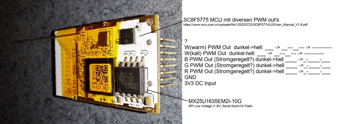
Leiterplatte mit MCU und Flash-Speicher
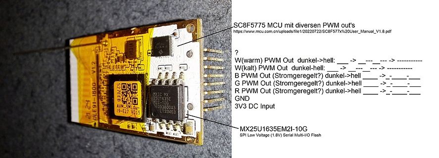
SC8F5775 MCU mit diversen PWM out's https://www.mcu.com.cn/uploads/file/1/20220722/SC8F577x%20User_Manual_V1.8.pdf ? W(warm) PWM Out dunkel->hell: __ -> ___ -> _________ W(kalt) PWM Out dunkel->hell: __ -> ___ -> _________ B PWM Out (Stromgeregelt) dunkel->hell: __ -> ___ -> _________ G PWM Out (Stromgeregelt) dunkel->hell: __ -> ___ -> _________ R PWM Out (Stromgeregelt) dunkel->hell: __ -> ___ -> _________ GND 3V3 DC Input MXIC MX 25U1635E EU53B00A5 L193463 MX25U1635EM2I-10G SPI Low
in „FRITZ!DECT 500 Lampe zu Steckdose(n) umbauen“ · Mikrocontroller und Digitale Elektronik · · Platinenfotos
-
Datei
PWM_test_tiny45.c
DDB1)|(1<<DDB4); //Ausgänge definieren TCCR0A=(1<<COM0A1)|(1<<COM0B1)|(1<<WGM01)|(1<<WGM00); //Fast-PWM, Timer0 TCCR0B=(1<<CS01); //Prescaler=8 => PWM=3,9kHz TCCR1=(1<<CS12); //Fast-PWM, Timer1 GTCCR=(1<<PWM1B)|(1<<COM1B1); //Prescaler=8 => PWM=3,9kHz //Vergleichregister setzen int vergleichswert=128; OCR1B=vergleichswert; OCR0A=vergleichswert; OCR0B=vergleichswert; // => PWM 50% an PB0(OC0A), PB1(OC0B), PB4(OC1B) } int main(void) { init_Device(); while(1) { } return 0; }
in „tiny45 3xHardware PWM“ · Mikrocontroller und Digitale Elektronik ·
-
 Bild
Bild
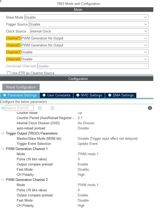
Konfigurationsmenü für TIM3 PWM-Generierung
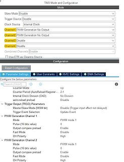
Configuration Mode Slave Mode Disable Trigger Source Disable Clock Source Internal Clock Channel1 PWM Generation No Output Channel2 PWM Generation No Output Channel3 Disable Channel4 Disable Combined Channels Disable Use ETR as Clearing Source Configuration Reset Configuration Parameter Settings User
in „STM32 Timer Problem“ · Mikrocontroller und Digitale Elektronik · · Screenshots
-
Datei
PWM_PA0-16-3.9khz.asm
;pwm an atmega16/32 für 2 khz (3,906) khz ;bei 4mhz taktfrequenz ;mit timer0 im fast pwm mode, 8 bit aufloesung ;pwm-signal liegt auf pb3 oc0 .include "m16def.inc" ;.def v_panel = r14 ;Messwert PV-Spannung
in „Hilfe Ladereglung Atmega16 Assembler“ · Mikrocontroller und Digitale Elektronik ·
-
Datei
V1_Taster.bas
Output 'LED Rot Config Portb.2 = Output 'LED Gruen Config Portb.3 = Output 'LED Blau Config Timer1 = Pwm , Pwm = 8 , Compare A Pwm = Clear Down , Compare B Pwm = Clear Down , Prescale = 1 Config Timer2 = Pwm , Pwm = On , Compare Pwm = Clear Down , Prescale = 1 Enable Timer1 Enable Timer2 Start Timer1 Start
in „Sehe den Fehler nicht - Bascom Problem“ · Mikrocontroller und Digitale Elektronik ·
-
 Bild
Bild
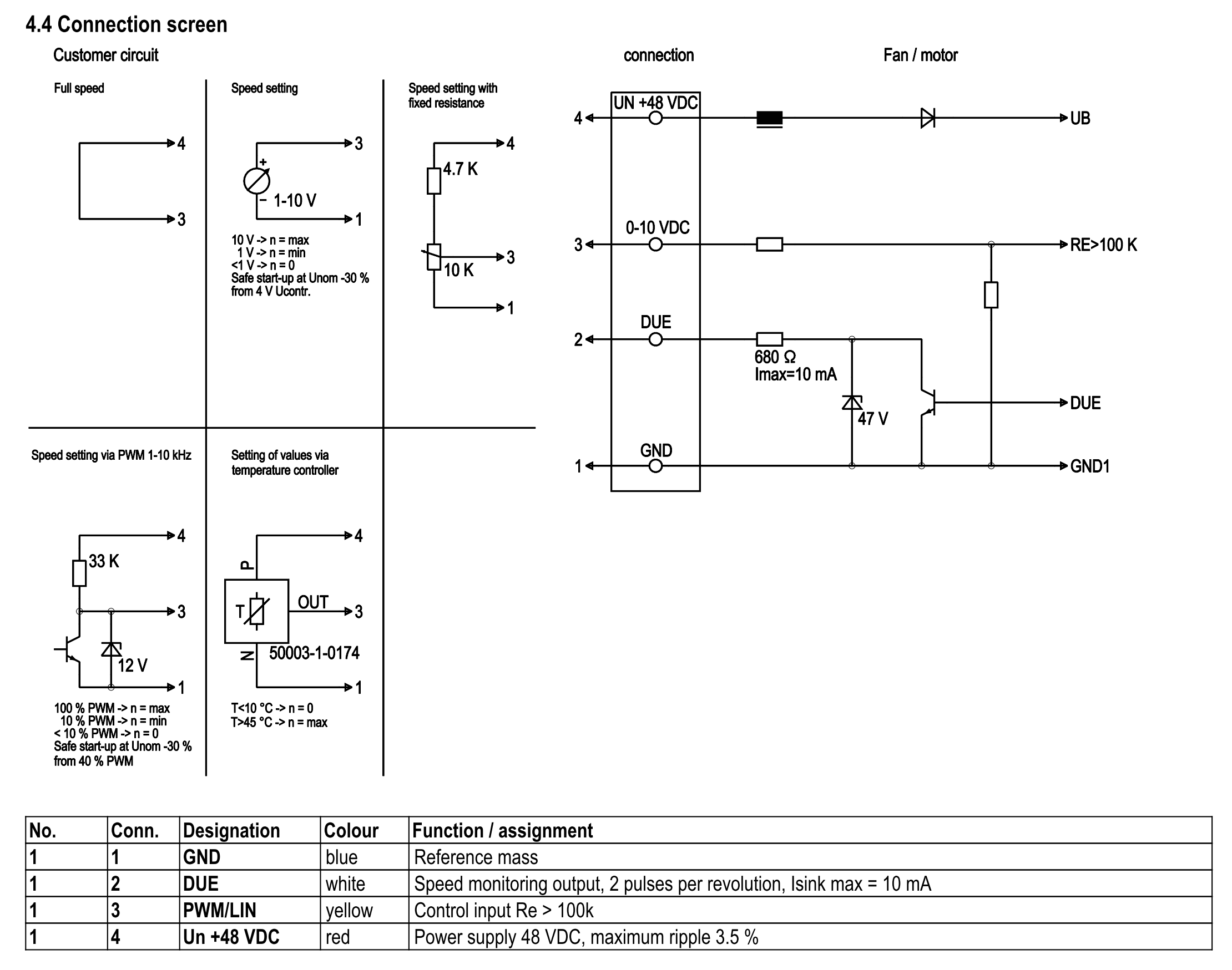
Schaltplan für Motorsteuerung und Geschwindigkeitseinstellung
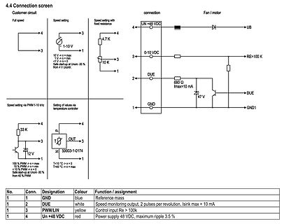
motor 10 V -> n = max 1 V -> n = min < V -> n = 0 Safe start-up at Unom -30 % from 4 V Unom Speed via PWM 1-10 kHz Setting of values via temperature controller 100 % PWM -> n = max 10 % PWM -> n = min 10 % PWM -> n = 10 Safe start-up at Unom -30 % from 40 % PWM T<10 °C -> n = 0 T=45 °C -> n = max UN +48
in „12 V PWM aus ESP32 funktioniert nur so "halb"“ · Mikrocontroller und Digitale Elektronik · · Schaltpläne
-
Datei
tiny13.bas
$crystal = 9600000 $hwstack = 16 $swstack = 5 $framesize = 16 Config Portb.0 = Output 'Ausgang für PWM an PB0 Config Timer0 = Pwm , Compare A Pwm = Clear Down , Prescale = 1 Config 1wire = Portb.4 'hier ist der DS18S20 angeschlossen 'Dimensionierung der Variablen: Dim temperatur As Byte 'Einstellung
in „Bascom vs. Assembler“ · Mikrocontroller und Digitale Elektronik ·
-
Datei
noname1.bas
$crystal = 9600000 $hwstack = 16 $swstack = 5 $framesize = 16 Config Portb.0 = Output 'Ausgang f?r PWM an PB0 Config Timer0 = Pwm , Compare A Pwm = Clear Down , Prescale = 1 Config 1wire = Portb.4 'hier ist der DS18S20 angeschlossen 'Dimensionierung der Variablen: Dim Temp As Byte 'Einstellung der Parameter
in „Bascom vs. Assembler“ · Mikrocontroller und Digitale Elektronik ·
-
Datei
PAC9533-schreiben.ino
#include <Wire.h> byte Input = B00010000; byte add = B01100010; // addresse byte PWM0 = B00000010; // PWM0 Register wahl byte PWM1 = B00000100; // PWM1 Register wahl byte PSC0 = B00000001; // PSC0 Register wahl byte PSC1 = B00000011; // PSC1 Register wahl byte LS0 = B00000101; // LS0 Register wahl byte LED = B11101110; // PWM0 -> LED 0.. PWM1 -> LED1 byte Daten1 = B10101010; // Daten 1 byte Daten2 = B01010101; // Daten 2 byte Daten3 = B00000101; // Daten 2 byte Daten4 = B01010000; // Daten 2 void setup() { Wire.begin();
in „PCA 9533 mit einem UNO ansteuern“ · Mikrocontroller und Digitale Elektronik ·
-
Datei
TB_PWM_MODULE_CLK_EN.vhd
library IEEE; use IEEE.STD_LOGIC_1164.all; use IEEE.NUMERIC_STD.all; entity TB_PWM_MODULE_CLK_EN is end TB_PWM_MODULE_CLK_EN; architecture tb of TB_PWM_MODULE_CLK_EN is component PWM_MODULE_CLK_EN is generic ( P : integer ); port ( CLK_100MHZ_PIN : in std_logic; ARESETN_PIN : in std_logic
in „Frequency Pre-Scaler von 100MHz zu 60 Hz“ · FPGA, VHDL & Co. ·
-
PDF
Chamaeleon_Schaltplan.pdf
+12V K +12V +12V +3V R 1 T1 LD1117V33 IRF540NS F In n 2 Out 10K T4 0 C GND PWM_R 1 S1 R7 BC847 K3 +12V +12V +3V 4 K 0 8 7 9 7 R 1 T2 1 1 R 4 R 4 K K IRF540NS Reset Reset TX TX 10K T5 ADC RX RX PWM_G CH_PD GPIO5 GPIO16 GPIO4 PWM_G R10 BC847 PWM_R GPIO14 GPIO0 Flush PWM_B GPIO12
in „Projektvorstellung RGB LED Steuerung (Chamäleon)“ · Projekte & Code ·
-
PDF
doc7707.pdf
(PWM (PWM Timer/Counter Mode OCRn x Flag de n3 ) n1) n0) of Operation TOP at Set on 0 0 0 0 0 Normal 0xFFF Immedi MAX F ate 1 0 0 0 1 PWM, Phase Correct, 0x00F TOP BOTTO 8-bit F M 2 0 0 1 0 PWM, Phase Correct
in „AVR (AT90USB162) - Sleep Mode und PCINT“ · Mikrocontroller und Digitale Elektronik ·
-
Datei
pwmdim.c
my_delay(uint16_t milliseconds) { for(; milliseconds>0; milliseconds--) _delay_ms(1); } // 10-Bit PWM with 64 different settings void pwm_10_64(uint16_t delay, int8_t *k10, *k11, *k20, *k21, *k30, *k31){ int16_t tmp; while (DDC0==1) //Kanal 1 dimmen { if((k10-k11)>0){ k10 = k11; for(tmp=k10; tmp<=63
in „Atmega 8 - 3 Kanal Dimmer, Ausgangsabfrage und Timerinitialisierung“ · Mikrocontroller und Digitale Elektronik ·
-
PDF
schaltplan-final.pdf
IN4 7 SCLK PB6 (MISO) PA6 (ADC6) KANTER 7 Motor MOT3 PWM1A 8 8 PB7 (SCK) PA7 (ADC7) 33 8 rechts 1 EN1 1 2 MOT4 EN2 9 PWM1B 1 RXD 14 PD0 (RXD) PC7 (TOSC2) 29 PC7 1 4 3 2 1 J5 2 TXD 15 PD1 (TXD) PC6 (TOSC1) 28 PC6 2 D D D D VS 8 VCC 3 CTS 16 PD2 (INT0) PC5 (TDI) 27 PC5 3 N N N N 16 RADR 17 26 PC4 L293D G G G G VSS 4 PWM1B 18 PD3 (INT1) PC4 (TDO) 25 PC3 4 5 PWM1A 19 PD4 (OC1B) PC3 (TMS) 24 PC2 5 1 1 5 4 6 KLAPPE 20 PD5 (OC1A) PC2 (TCK) 23 PC1 6 7 PWM2 PD6 (ICP1) PC1 (SDA) PC0 7 POW1 J3 VCC 8 21 PD7 (OC2) PC0 (SCL) 22
in „LCD DEM20485 in gerade Zeile springen (c't-Bot)“ · Mikrocontroller und Digitale Elektronik ·
-
PDF
datasheet_FLEX003__v1_03.07.2008_.pdf
Pin 22 OC8/UPDNCN16/RD7 Pin 23 C2TX/RG1 Pin 24 C1TX/RF1 Pin 25 AN22/CN22/RA6 Pin 26 C2RX/RG0 Pin 27 PWM1L/RE0 Pin 28 AN23/CN23/RA7 Pin 29 CSCK/RG14 Pin 30 PWM1H/RE1 Pin 31 CSD0/RG13 Pin 32 CSDI/RG12 Pin 33 PWM2H/RE3 Pin 34 PWM2L/RE2 Pin 35 COFS/RG15 Pin 36 PWM3L/RE4 Pin 37 PWM4L/RE6 Pin 38 PWM3H/RE5 Pin 39 AN16/T2CK/T7CK/RC1 Pin 40 PWM4H/RE7 Figure 3: FLEX Full Base Board Dimensions
in „LED blinken lassen“ · Mikrocontroller und Digitale Elektronik ·
-
PDF
msp-m_map-m_1pi.pdf
Demodulator MAP 0 ◆ (Very) High deviation modes HDEV2, 3 ◆ Micronas Audio Evaluation Board D/A or PWM output MSP/MAP 1 ◆ Automatic Standard Detection (ASD) configuration 2 ◆ Automatic Sound Select (ASS) e.g. MSP 5651M: MSP-M with Download RAM, “Hi-Resolu- tion” PWM and NICAM switches mono/stereo/bilingual
in „suche Datenblatt/Pinbelegung für Micronas MAP5401“ · Mikrocontroller und Digitale Elektronik ·
-
PDF
D100940D.pdf
Figure 1 TDA 16831/2/3/4 Pin Definitions and Functions Pin Symbol Function 1 N.C. Not Connected 2 FB PWM Feedback Input 3 N.C. Not Connected 4 D 600 V Drain CoolMOS 5 D 600 V Drain CoolMOS 6 N.C. Not Connected 7 V PWM Supply Voltage CC 8 GND PWM GND and Source of CoolMOS Version 2.0 6 8 Aug 2002 TDA 16831
in „Wie startet dieses SNT ?“ · Mikrocontroller und Digitale Elektronik ·
-
PDF
2207251030_Mixic-MX1616H_C5119044-1.pdf
OFF OFF OFF ON ON OFF ON ON a) Standby mode b) Forward mode c) Reversal pattern d) Braking mode e) PWM Mode A When the input signal INAx is a PWM signal and INBx=0 or INAx=0 and INBx is a PWM signal, the motor rotation speed will be affected by the PWM. In this mode, the motor drive circuit switches
in „MX1616H Dual H-Bridge Motor Driver“ · Analoge Elektronik und Schaltungstechnik ·
-
PDF
bd623x.pdf
L Forward (OUT1 > OUT2) c L H VCC L H Reverse (OUT1 < OUT2) d H H X L L Brake (stop) __________ e PWM L VCC H PWM Forward (PWM control) __________ f L PWM VCC PWM H Reverse (PWM control) __________ g H L Option H PWM Forward (VREF control) __________ h L H Option PWM H Reverse (VREF control) * Hi-Z
in „2x Motoren (12V / 2A) mit PWM ansteuern (µC PIC)“ · Mikrocontroller und Digitale Elektronik ·
-
 Bild
Bild
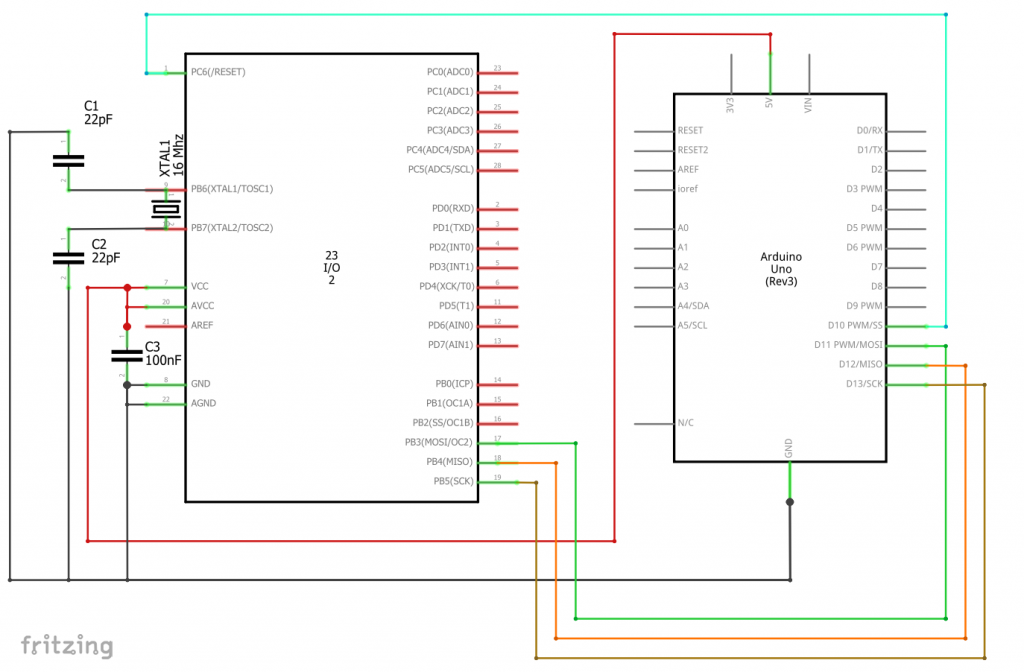
Schaltplan eines Arduino Uno mit ATmega328P
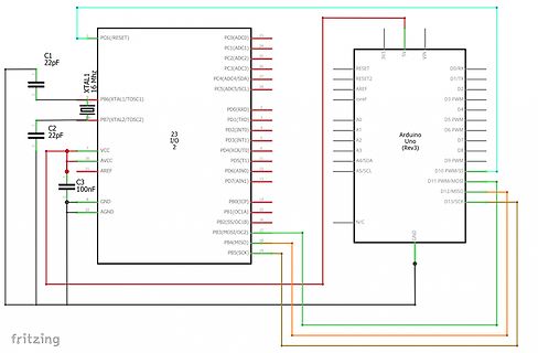
AREF, GND, AGND, Arduino Uno (Rev3), RESET, RESET2, AREF, IOREF, 5V, 3V3, VIN, D0/RX, D1/TX, D2, D3 PWM, D4, D5 PWM, D6 PWM, D7, D8, D9 PWM, D10 PWM/SS, D11 PWM/MOSI, D12/MISO, D13/SCK, A0, A1, A2, A3, A4/SDA, A5/SCL, N/C, GND, fritzing
in „Probleme mit FTDI232 Adapter“ · Mikrocontroller und Digitale Elektronik · · Schaltpläne
-
 Bild
Bild
Blockschaltbild eines Mikrocontrollers
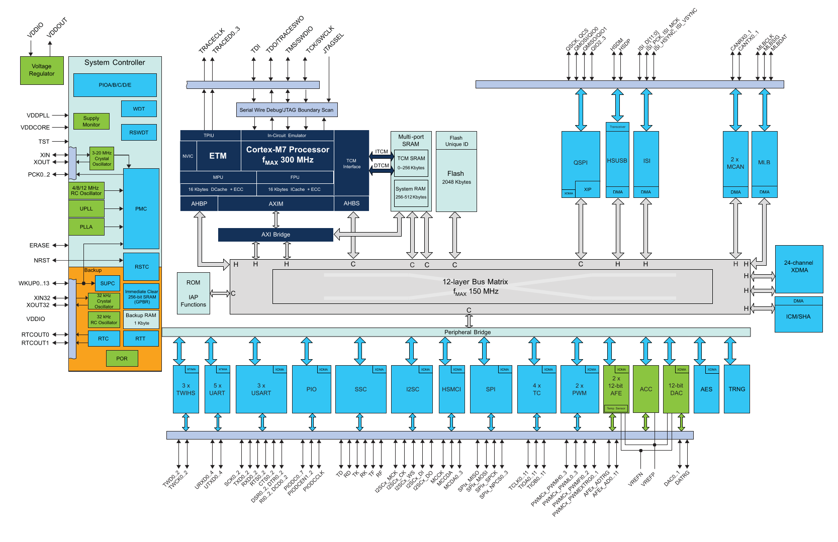
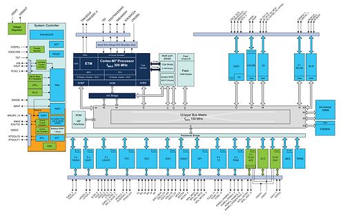
XDMA, 24-channel, DMA, Peripheral Bridge, 3 X, TWISS, UART, 5 X, USART, I2SC, HSMCI, SPI, 4 X, TC, PWM, 2 X, PWM, 12-bit DAC, ACC, 12-bit AES, TRNG, NFE, NFE, VREF N, VREFF, DAC, DATING, TCJ0, TCJ1, PWM0, PWM1, PWM2, PWM3, AEFX_0, AEFX_1, AEFX_2, AEFX_3, SD, TD, TR, TF, DISC_CK, DISC_CK, DISC_CK, MCCDA
in „Neue Bauteile: ESP32-C5 in Produktion, spulenloses Relais und neue Mikrocontroller“ · Mikrocontroller und Digitale Elektronik · · Diagramme
-
 Bild
Bild
Schaltplan und Anschlussbelegung eines Ventilators
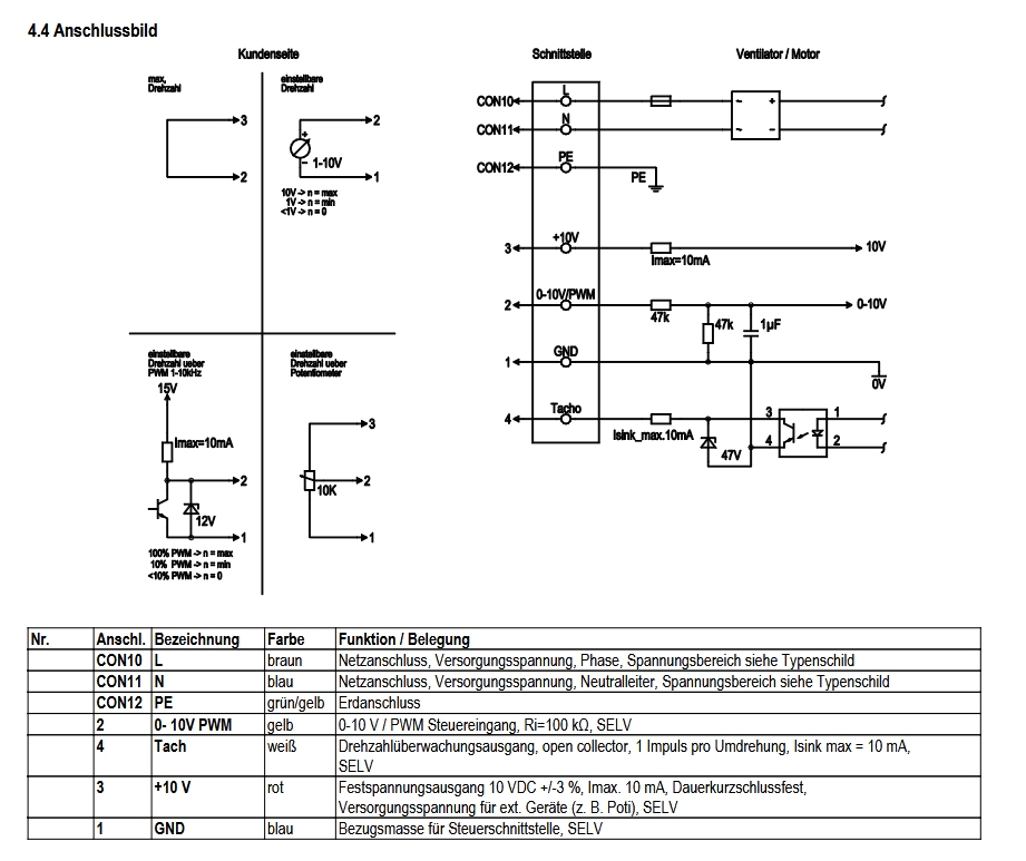
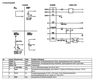
Drehzahl 1-10V 2 1 10V -> n = max 1V -> n = min <1V -> n = 0 CON10 L CON11 N CON12 PE 3 +10V 2 0-10V/PWM 4 Tach 1 GND Imax=10mA 47k 1uF 0V 0-10V Isink_max.10mA 47 15V 12V 100% PWM -> n = max 10% PWM -> n = min <10% PWM -> n = 0 Nr. Anschl. Bezeichnung Farbe Funktion / Belegung CON10 L braun Netzanschluss
in „Sind nicht-isolierte 10V gefährlich?“ · Analoge Elektronik und Schaltungstechnik · · Schaltpläne
-
Datei
main.h
GPIO_PIN_12 #define SDMMC_CK_GPIO_Port GPIOC #define ARDUINO_PWM_D9_Pin GPIO_PIN_15 #define ARDUINO_PWM_D9_GPIO_Port GPIOA #define SWCLK_Pin GPIO_PIN_14 #define SWCLK_GPIO_Port GPIOA #define SWDIO_Pin GPIO_PIN_13 #define SWDIO_GPIO_Port GPIOA #define DCMI_D6_Pin
in „Game of Life läuft nur eine Runde!“ · Mikrocontroller und Digitale Elektronik ·
-
Datei
main.c
* MA 02110-1301, USA. */ #include <avr/io.h> #include <avr/interrupt.h> #include "adc.h" #include "pwm.h" #include "highvoltage.h" #include "temperature.h" #include "leds.h" void main(void){ // INITZILASATION adc_init(ADC_supplyvoltageref); highvoltage_init(); temperature_init(); led_green_on(); led_yellow_on(); //led_yellow_off(); //led_green_off(); pwm_init(); pwm_set_width(1024); pwm_set_val(512); pwm_direction(pwm_direction_0); sei(); while(1){ PINB=0xFF; } }
in „sprintf verfälscht adc werte“ · Mikrocontroller und Digitale Elektronik ·
-
Datei
main.c
* MA 02110-1301, USA. */ #include <avr/io.h> #include <avr/interrupt.h> #include "adc.h" #include "pwm.h" #include "highvoltage.h" #include "temperature.h" #include "leds.h" void main(void){ // INITZILASATION adc_init(ADC_supplyvoltageref); highvoltage_init(); temperature_init(); led_green_on(); led_yellow_on(); //led_yellow_off(); //led_green_off(); pwm_init(); pwm_set_width(1024); pwm_set_val(512); pwm_direction(pwm_direction_0); sei(); while(1){ PINB=0xFF; } }
in „sprintf verfälscht adc werte“ · Mikrocontroller und Digitale Elektronik ·
-
Datei
Progausschnitt.txt
clr R_PWM ;PWM-Register loeschen ldi rmp,(1<<CS01);(1<<CS01) ; Timer Prescaler auf 8 für PWM out TCCR0B,rmp ldi rmp,(1<<COM0A1)|(1<<WGM01)|(1<<WGM00) ; Fast PWM mode, A nichtinvertierter Output out TCCR0A,rmp Abfrage2: out OCR0A,R_PWM ;PWM-Wert in Vergleichsregister laden sbis PinB,PB4 ;überspringe naechsten Befehl, wenn Ausgang PB4 gesetzt rjmp Abfrage2 sbi PortB,PB2 ;Freigabe der Motorkarte loeschen, keine Freigabe durch H-Signal
in „ATtiny 13 Eingang wird zu langsam erkannt“ · Mikrocontroller und Digitale Elektronik ·
-
Datei
code_tiny13.txt
$crystal = 9600000 $hwstack = 16 $swstack = 5 $framesize = 16 Config Portb.0 = Output 'Ausgang für PWM an PB0 Config Timer0 = Pwm , Compare A Pwm = Clear Down , Prescale = 1 Config 1wire = Portb.4 'hier ist der DS18S20 angeschlossen 'Dimensionierung der Variablen: Dim Variable1 As Byte Dim Variable2
in „Bascom vs. Assembler“ · Mikrocontroller und Digitale Elektronik ·
-
Datei
Ini.h
#ifndef INI_H_INCLUDED #define INI_H_INCLUDED void Ini(void); void Ini_PWM(void); void Ini_Led(void); void Ini_Rs232(void); void Ini() { Ini_Led(); Ini_PWM(); Ini_Rs232(); } //Enable für die LED beleuchtung void Ini_Led() { DDRD |= ((1 << Led_Enable_Weiss) | (1 << Led_Enable_Blau)); } //PWM für Timer_1 void Ini_PWM() { //Timer_1 mit einem Prescale von 8 TCCR1B |= (1 << CS11); //Timer_1 in den Fast PWM Mode 10 Bit schalten TCCR1A |= (1 << WGM10) | (1 << WGM11); TCCR1B |= (1 << WGM12); /
in „RS232 gibt kein Signal aus“ · Mikrocontroller und Digitale Elektronik ·
-
Datei
Test.c
#include <avr/io.h> void timer0_init_PWM_phasecorrect(); void ADC_wandlung(); int main() { start: timer0_init_PWM_phasecorrect(); ADC_wandlung(); //while(1); goto start; } //*************************************************************** //** PWM Signal ** //*************************************************************** void timer0_init_PWM_phasecorrect() //PWM Signal an PD6 { DDRD = 0xFF; // Alle Pins von Port D als Ausgang definiert TCCR0A
in „AD-Wandler steuert PWM in C“ · Mikrocontroller und Digitale Elektronik ·