
-
Datei
2017.txt
,#0 mov 5ah,#0 mov 5bh,#0 mov 70h,#0 mov 4ch,#0 mov 4fh,#0 X02a7: ret ; X02a8: mov 4ch,#1 mov 5eh,#24h mov 5fh,#1 mov 59h,#4 mov 4dh,#0ffh anl 67h,#0dfh anl 69h,#0dfh mov 72h,#0 mov a,65h jb acc.0,X02c7 clr p1.4 X02c7: ret ; X02c8: anl 65h,#0feh anl 27h,#0feh orl 27h,#2 lcall X0ec3 mov a,64h anl a,#2
in „8031er Programm zurückholen.“ · Mikrocontroller und Digitale Elektronik ·
-
PDF
AVR-DD-Product-Brief-DS40002215A-1.pdf
as follows: ® Figure 2. AVR DD Device Designations AVR64DD32T - E/RXB Flash size in KB Package Style RXB = VQFN32 Family PT = TQFP SS = SSOP SO = SOIC SP = SPDIP Pin count Temperature Range I = -40°C to +85°C (Industrial) E = -40°C to +125°C (Extended) Carrier
in „AVR-DD im Anrollen“ · Mikrocontroller und Digitale Elektronik ·
-
Datei
deinterleave2.lst
, r22 14c: b6 95 lsr r27 14e: a7 95 ror r26 150: 97 95 ror r25 152: 87 95 ror r24 154: 9c 01 movw r18, r24 156: 21 70 andi r18, 0x01 ; 1 158: 30 70 andi r19, 0x00 ; 0 uint16_t odd = 0; uint16_t even = 0; if( in
in „AVR/ATmega uint32_t Deinterleaving optimieren“ · Mikrocontroller und Digitale Elektronik ·
-
Datei
zeichensatz8x5.c
, /*`*/{0,1,2,4,0}, /*a*/{32,84,84,84,120}, /*b*/{127,72,68,68,56}, /*c*/{56,68,68,68,32}, /*d*/{56,68,68,72,127}, /*e*/{56,84,84,84,24}, /*f*/{8,126,9,1,2}, /*g*/{24,164,164,164,124}, /*h*/{127,8,4,4,120}, /*i*/{0,68,125,64,0}, /*j*/{32,64,68,61,0}, /*k*/{127,16,40,68,0}, /*l*/{0,65,127,64,0}, /*m*/{124,4,24,4,120}, /*n*/{124,8,4,4,120}, /*o*/{56,68,68,68,56}, /*p*/{252,36,36,36,24}, /*q*/{24,36,36,36,252}, /*r*/{124,8,4,4,8}, /*s*/{72,84,84,84,36}, /*t*/{4,63,68,32,0}, /*u*/{60,64,64,32,124
in „Zeichensatz 8x5 für Led Display“ · Mikrocontroller und Digitale Elektronik ·
-
PDF
Bauteile_verkauf_1120.pdf
10 8,- (Historisch) 8051-Mikrocontroller mit UV-Fenster: P87C750 (EPROM 1K) DIP24S 5 6,- P87C751 (EPROM 2K) DIP24S 7 6,- S87C752 (EPROM 2K,A/D-Wandler) DIP28 3 8,- P87C550 (EPROM 4K, A/D-Wandler) DIP40 4 10,- 8051-Mikrocontroller Romless, Flash oder OTP: SC87C51CCA44
in „[V] ICs, Mikrocontroller etc. aus Lagerräumung“ · Markt ·
-
Datei
Devices.txt
4013D 27 SMD5 27 SMD2 27 R-EU_R0805W 27 R-EU_0411/15 27 MEGA32-P 27 CRYTALHC49S 27 CPOL-EUE2-5 27 C-EU050-035X075 27 78XXL 26 R-R1206 26 CAPNP-5 25 CRYTALHC18U-V 25 CPOL-EUE1.8-4 25 C-EUC1206K 25 C2.5/4 24 ZPD 24 ULN2803A 24 SCHOTTKY-DIODEDO35-7 24 SAL41B 24 RS485-DUPLEX-SN65HVD30 24 RCL_C-EUC1206K
in „[KiCad] Bibliotheksaufbau - Konzeptideen gesucht“ · Platinen ·
-
Datei
LiedKlingel2017.ino
/1/16 6, //1/16. 8, //1/8 12,//1/8. 16,//1/4 24,//1/4. }; const uint8_t lied[] PROGMEM = { 1 //Lied Nr. 1 Offset:0 ,0,136,128,107,128,72,64,72,141,136,134,136,128,111,128,72,64,72,144,143,139,136,143,148,72,70,64,70,131,139,200,200,192,82,143,141,139,200,171,72,64,72,141,136,134,200,175,72,64,72,144,143,139,136,143,148,72,70,64,70,131,139,200,200
in „Klingel mit 100 Melodien - last minute Weihnachtsgeschenk“ · Projekte & Code ·
-
PDF
2599932.pdf
See page 23 ) .070 22-18 0.3-1.0 .012 63236-1 31-28 0.23-0.32 1.78 0.30 Typical Cavity Size 6, when “C” .070 .012 [ ] 1.78 24-20 0.2-0.6 0.30 1742614-1 dimension is .070 1.78 .120 .012 See page 23 ) 30-27 0.25-0.36 3.05 24-20 0.2-0.6 0.30 62992-1 C 300 Box .120 .012 Standard IDC 28-24 0.32-0.51 3.05 24
in „IDC connector für Kupferlackdraht“ · Mikrocontroller und Digitale Elektronik ·
-
PDF
surrpressordiode.pdf
15.2 39.4 (+) SMBJ22A LX BX 24.4 26.9 1.0 22 1.0 16.9 35.5 (+SMBJ24 LY BY 26.7 32.6 1.0 24 1.0 14.0 43.0 (+SMBJ24A LZ BZ 26.7 29.5 1.0 24 1.0 15.4 38.9 (+) SMBJ26 MD CD 28.9 35.3 1.0 26 1.0 12.9 46.6 (+SMBJ26A ME CE 28.9 31.9 1.0
in „DC Geräteeingang“ · Analoge Elektronik und Schaltungstechnik ·
-
PDF
CY7C68013.pdf
eight-byte buffer at 0xE6B8-0xE6BF holds the SETUP data from a CONTROL transfer. Document #: 38-08012 Rev. *C Page 14 of 52 CY7C68013 3.12.4 Endpoint Configurations (High-speed Mode) EP0 IN&OUT 64 64 64 64 64 64 EP1 IN 64 64 64 64 64 64 EP1 OUT 64 64 64 64 64 64 512 512 512 EP2 1024 1024 1024 512 512 EP2 512
in „Stereokamera CY7C68013A + 2 mal MT9D131“ · Mikrocontroller und Digitale Elektronik ·
-
PDF
CY7C68016A.pdf
high-speed end- point configuration options, see Figure 3-5. Document #: 38-08032 Rev. *K Page 9 of 60 CY7C68013A/CY7C68014A CY7C68015A/CY7C68016A EP2–1024 double buffered; EP6–512 quad buffered (column 8). EP0 IN&OUT 64 64 64 64 64 64 64 64 64 64 64 64 EP1 IN 64 64 64 64 64 64 64 64 64 64 64 64 EP1 OUT 64
in „CY7C68013A-56pins“ · Mikrocontroller und Digitale Elektronik ·
-
PDF
Funkschau_Inhalt_1980-1990.pdf
für Funkamateure 85/16/61 C-64-Softwaretip; REM-Killer für Kommentare 85/24/77 C-64-Softwaretip; Zeichenvorrat ändern 85/4/63 CAE; Reißbrett ade - Konstruieren am Bildschirm 85/4/57 Commodore-1541-Hardwaretip; FloppyAdresse ändern
-
Datei
TEST.LST
__bad_interrupt> 1e: 1c c0 rjmp .+56 ; 0x58 <__bad_interrupt> 20: 1b c0 rjmp .+54 ; 0x58 <__bad_interrupt> 00000022 <__ctors_end>: 22: 11 24 eor r1, r1 24: 1f be out 0x3f, r1 ; 63 26: cf e5 ldi r28, 0x5F ; 95 28: d2 e0 ldi
in „Problem inline Assembler“ · Mikrocontroller und Digitale Elektronik ·
-
Datei
test.txt
defined(TCCR3B) && defined(CS31) && defined(WGM30) sbi(TCCR3B, CS31); // set timer 3 prescale factor to 64 21c: 80 91 91 00 lds r24, 0x0091 ; 0x800091 <__TEXT_REGION_LENGTH__+0x700091> 220: 82 60 ori r24, 0x02 ; 2 222: 80 93 91 00 sts 0x0091, r24 ; 0x800091 <__TEXT_REGION_LENGTH__+0x700091> sbi(TCCR3B, CS30
in „Arduino Compiler Speicherverwaltung“ · Mikrocontroller und Digitale Elektronik ·
-
Datei
t1.c
, 0x31,0x4c, 0x64,0x39, 0x25 ,0x23, 0x1b,0x12, 0x1d,0x1d, 0x2a,0x4b, 0x3a,0x56, 0x40,0x3c, 0x3f,0x51, 0x50,0x63, 0x69 ,0x54, 0x4c,0x43, 0x3d,0x4e, 0x46,0x22, 0x2a,0x22, 0x24,0x2a, 0x4a,0x5a, 0x60,0x4a, 0x46 ,0x32
in „Grafik um sub-pixel Entfernung verschieben“ · Digitale Signalverarbeitung / DSP / Machine Learning ·
-
PDF
b8_handbuch_1205.pdf
/1 1/1 - - 10 25 18F2525 28 48 1024 4 2 2 1/1 1/1 - - 10 25 18F2550 28 32 256 4 2 2 1/1 1/1 - 1 10 24 18F2553 28 32 256 4 2 2 1/1 1/1 - 1 10 24 18F2580 28 32 256 4 1 1 1/1 1/1 1 - 8 25 18F2585 28 48 1024 4 1 1 1/1 1/1 1 - 8 25 18F2610 28 64 - 4 2 2 1/1 1/1 - - 10 25 18F2620 28 64 1024 4 2 2 1/1 1/1 -
in „PIC16f628 programmieren“ · Mikrocontroller und Digitale Elektronik ·
-
PDF
datasheet_SC16IS750.pdf
sheet Rev. 01 Ñ 4 January 2006 7 of 61 Philips Semiconductors SC16IS740/750/760 Single UART with I C-bus/SPI interface, 64-byte FIFOs, IrDA SIR Table 2: Pin description ”continued Symbol Pin Type Description TSSOP16 TSSOP24 HVQFN24 CS/A0 2 9 6 I SPI chip select or I C-bus device address select A0. If
in „UART_Initialisierung“ · Mikrocontroller und Digitale Elektronik ·
-
Datei
GenericTypeDefs.h
int UINT; typedef unsigned char UINT8; typedef unsigned short int UINT16; /* 24-bit type only available on C18 */ #if defined(__18CXX) typedef unsigned short long UINT24; #endif typedef unsigned long int UINT32; /* other name for 32-bit integer */ /* MPLAB C Compiler for PIC18 does
in „Anfängerproblem PIC18“ · Mikrocontroller und Digitale Elektronik ·
-
Datei
TerminalLog.txt
*66 $GPGGA,141146.000,,,,,0,00,,,M,0.0,M,,0000*51 $GPGSA,A,1,,,,,,,,,,,,,,,*1E $GPGSV,3,1,10,09,64,302,,15,48,171,,17,40,078,24,12,38,230,*7D $GPGSV,3,2,10,26,34,157,,18,24,265,15,05,22,236,,22,19,306,*7C $GPGSV,3,3,10,28,17,053,,14,00,321,*77 $GPRMC,141146.000,V,,,,,,,150708,,,N*41 $PBB50,0,0.1,0.0,0,0,1.00,0,00*4B $GPGGA,141147.000,,,,,0,00,,,M,0.0,M,,0000*50 $GPGSA,A,1,,,,,,,,,,,,,,,*1E $GPGSV,3,1,10,09,64,302,,15,48,171,,17,40,078,25,12,38,230,*7C $GPGSV,3,2,10,26,34,157,,18,24,265,15,05,22,236,,22,19,306,*7C $GPGSV,3,3,10,28,17,053,,14,00,321,*77 $GPRMC,141147.000,V,,,,,,,150708,,,N*40 $PBB50,0,0.0,0.0,0,0,1.00,0,00
in „GPS Daten empfangen und wieder senden“ · Mikrocontroller und Digitale Elektronik ·
-
Datei
dw_programming_dragon.txt
14] . [c0] . [13] . [c0] . [12] . [c0] . [11] . [c0] . [10] . [c0] . [11] $ [24] . [1f] . [be] . [cf] . [ef] . [d1] . [e0] . [de] . [bf] . [cd] . [bf] . [11] . [e0] . [a0] . [e0] . [b1] . [e0] . [01] . [c0] .
in „avrdude fuses aus debugwire schreiben“ · Mikrocontroller und Digitale Elektronik ·
-
Datei
deinterleave2__2_.lst
r23, 2 92: 20 62 ori r18, 0x20 ; 32 if( in & 1UL<<12 ) odd |= 1UL<<6; 94: 74 fd sbrc r23, 4 96: 20 64 ori r18, 0x40 ; 64 if( in & 1UL<<14 ) odd |= 1UL<<7; 98: 76 fd sbrc r23, 6 9a: 20 68 ori r18, 0x80 ; 128 if( in & 1UL<<16 ) odd |= 1UL<<8; 9c: 80 fd sbrc r24, 0 9e: 31 60 ori r19, 0x01 ; 1 if( in & 1UL
in „AVR/ATmega uint32_t Deinterleaving optimieren“ · Mikrocontroller und Digitale Elektronik ·
-
PDF
lcd.pdf
/---156.0 x 20.0 1/24 G Y W N - E PCB 240 x 64 PVG240602A ■■ 180.0 x 65.0x 10.0/14.5132.6 x 39.0 1/64 G Y W N L E T6369C PCB 240 x 64 PVG240602B ■■ 180.0 x 65.0x 10.0/14.5132.6 x 39.0 1/64 G Y W N L E T6369C PCB, DC/DC 320
in „LCD Display“ · Mikrocontroller und Digitale Elektronik ·
-
PDF
DC02EN.pdf
Weight lb (kg) 7.0 (3.18) 7.5 (3.40) 8.0 (3.63) 9.0 (4.08) Step 3: Available Windings Imperial 90V24 90V48 90V60 120V24 120V48 120V60 185V24 185V48 185V60 200V24 200V48 200V60 Metric 64V24 64V48 64V60 85V24 85V48 85V60 130V24 130V48 130V60 141V24 141V48 141V60 Voltage 24 48 60 24 48 60 24 48 60 24 48
in „[V] 2 Elektromotoren“ · Markt ·
-
PDF
SSD1305.pdf
Table 10-1 : Example of Set Display Offset and Display Start Line with no Remap Output 64 64 64 56 56 56 Set MUX ratio(A8h) Normal Normal Normal Normal Normal Normal COM Normal / Remapped (C0h / C8h) Hardware 0 8 0 0 8 0 Display offset (D3h) pin name 0 0 8 0 0 8 Display start line (40h -
in „i2c lese problem“ · Mikrocontroller und Digitale Elektronik ·
-
PDF
DSASW00146882.pdf
Table 10-1 : Example of Set Display Offset and Display Start Line with no Remap Output 64 64 64 56 56 56 Set MUX ratio(A8h) Normal Normal Normal Normal Normal Normal COM Normal / Remapped (C0h / C8h) Hardware 0 8 0 0 8 0 Display offset (D3h) pin name 0 0 8 0 0 8 Display start line (40h -
in „OLED Display mit ssd1305 Chip“ · Mikrocontroller und Digitale Elektronik ·
-
Datei
EMSlog.txt
{CE} 20:13:04 07.03.12: 30 08 35 00 00 00 00 CE {2A} 20:13:04 07.03.12: 21 00 AB 00 1B 01 08 64 64 01 10 2A {C4} 20:13:33 07.03.12: 10 00 06 00 7.3.2012 20:12.29 Mi 00 C4 {BD} 20:13:35 07.03.12: 10 21 AC 00 1B 64 03 BD {A9} 20:13:36 07.03.12: 10 08 1A 00 2C 64 64 00 A9 {00} 20:13:39 07.03.12: 10
in „Buderus EMS-"Gateway" mit PIC18F / Sammelbestellung“ · Haus & Smart Home ·
-
PDF
SSD1303.pdf
[5:0] * * B5 B4 B 3 B2 B 1 B0 Color B: B[5:0] same as above (RESET = 111111b) 0 C[5:0] * * C5 C4 C 3 C2 C 1 C0 Color C: C[5:0] same as above (RESET =111111b) Note: color D pulse width is fixed at 64 clocks pulse. SSD1303 Rev 2.6 P 25/57 Oct 2007 Solomon Systech D/C Hex D7 D6 D5 D4
-
PDF
KS0108.pdf
V4 4R 4L V 3RV3L V3 VEE VEE CLK1 CLK1 VEE1 EE2 VEE CLK2 CLK2 V CL2 CL2 SS V S6B0107 SS VDD VDD S1 S64 SHL FS MS PCLK2 SEG1 SEG64 SD2 C1 COM1 DS1 LCD V C64 COM64 SS VDD V0 R 1 V 1 R1 V 2 R2 V 3 R1 V4 R1 V5 VEE 24 64CH SEGMENT DRIVER FOR DOT MATRIX LCD S6B0108 TIMING DIAGRAM (1/64DUTY) CLK1 1 2 3 48 49
in „KS0108 library und Timing diagram“ · Mikrocontroller und Digitale Elektronik ·
-
PDF
MB91F465DA-FujitsuMediaDevices.pdf
mode (MD[2:0] = 111): MB91F467Dx MB91F465DA FA[21:0] FA[20:0] 003F:FFFFh 001F:FFFFh 003F:0000h SA23 (64KB) 001F:0000h SA19 (64KB) 003E:FFFFh 003E:0000h SA22 (64KB) 001E:FFFFh SA18 (64KB) 001E:0000h 003D:FFFFh SA21 (64KB) 001D:FFFFh 003D:0000h 001D:0000h SA17 (64KB) 003C:FFFFh SA20 (64KB) 003C:0000h 001C
in „LCD Display / Controller eines Schweißgerätes prüfen“ · Mikrocontroller und Digitale Elektronik ·
-
PDF
YAMAICHI_TS-Katalog-2017_01_2.pdf
0.85 1 32.1 x 26.7 14 x 14 OT NP506-056-051-SCG 56 7 x 7 0.75 1 25 x 25 17 x 17 OT IC549-0644-008 64 8 x 8 0.5 -1.2 No 24.5 x 22 16 x 16 LID IC549-0644-008-G 64 8 x 8 0.5 -1.2 1 24.5 x 22 16 x 16 LID NP506-064-038-S 64 8 x 8 0.75 No 36 x 31 16 x 16 OT NP506-064-038-SG 64 8 x 8 0.75 1 36 x 31 16 x 16
in „TSOP-66 Sockel zum testen“ · Mikrocontroller und Digitale Elektronik ·
-
PDF
Data_sheet_XBee_XBee-Pro_Series_2.pdf
Humidity / (1.0546 - (0.00216 * Temperature (°C))) Looking at the sample data, we have: Vsupply = (234 * 5.1 / 255) = 4.68 Voutput = (82 * 5.1 / 255) = 1.64 Temperature = (362 / 16) = 22.625°C Relative H = (161.2903 * ((1.64/4.68) - 0.16)) = 161.2903
-
PDF
pt100.pdf
Temperature Measurement Technical Data Sheet TD-TV/PT1A PT100 Resistance Table ºC 0 1 2 3 4 5 6 7 8 9 ºC -200.00 18.52 -200.00 -190.00 22.83 22.40 21.97 21.54 21.11 20.68 20.25 19.82 19.38 18.95 -190.00 -180.00 27.10 26.67 26.24 25.82 25.39 24.97 24.54 24.11 23.68 23.25 -180.00 -170.00
in „Pt100 auswerten“ · Mikrocontroller und Digitale Elektronik ·
-
PDF
NTCLE100E-SERIES_ENG_TDS.pdf
4.00 1.18 20 39.94 56.88 82.29 - 3.88 0.58 25 33.00 47.00 68.00 - 3.76 0.00 30 27.43 39.06 56.51 - 3.64 0.56 35 22.92 32.64 47.23 - 3.54 1.11 40 19.26 27.42 39.68 - 3.43 1.63 45 16.26 23.16 33.50 - 3.34 2.14 50 13.79 19.65 28.42 - 3.24 2.63 55 11.76 16.74 24.23 - 3.15 3.11 60 10.06 14.33 20.74 - 3.07 3.57
in „Gaggenau Backofen NTC-Luftfühler defekt“ · Haus & Smart Home ·
-
PDF
NTCLE100E-SERIES_ENG_TDS.pdf
4.00 1.18 20 39.94 56.88 82.29 - 3.88 0.58 25 33.00 47.00 68.00 - 3.76 0.00 30 27.43 39.06 56.51 - 3.64 0.56 35 22.92 32.64 47.23 - 3.54 1.11 40 19.26 27.42 39.68 - 3.43 1.63 45 16.26 23.16 33.50 - 3.34 2.14 50 13.79 19.65 28.42 - 3.24 2.63 55 11.76 16.74 24.23 - 3.15 3.11 60 10.06 14.33 20.74 - 3.07 3.57
in „Defekt bei Sentiotec Sauna/Infrarotkabinen-Steuerung“ · Haus & Smart Home ·
-
PDF
Visio_120-22-R2C.pdf
• Kompakt- SPS Vision120-22-R2C µ-SPS mit graf. Bedienfeld (128 x 64) Merkmale • Grafikfähiges LCD-Display (128x64 Pixel) • Bedienfeld mit 16 Eingabetasten • 10 digitale Eingänge, 6 Relaisausgänge, 2 analoge Eingänge • 2x RS-232 oder
in „MINI-SPS mit AVR od. ARM“ · Mikrocontroller und Digitale Elektronik ·
-
Datei
transceiver_test_v3_twr.html
Delay (ns) Site Resource PADI_DEL --- 0.259 87.PAD to 87.PADDI VCXO_24R ROUTE 1 0.805 87.PADDI to R13C6A.CLK VCXO_24R_c REG_DEL --- 0.137 R13C6A.CLK to R13C6A.Q0 RECEIVER/PLL_MODUL/CLK_DIVIDER/SLICE_78 ROUTE 5 0.394 R13C6A.Q0 to R14C5C.CLK RECEIVER/sync_cnt_i_1 REG_DEL
in „Desig/Routing Probleme bei Lattice MachXO2280“ · FPGA, VHDL & Co. ·
-
PDF
picdream.asm.pdf
CALL Showline ;64 BCF Sync ; 1 Ligne24 CALL Showline ;64 BCF Sync ; 1 Ligne25 CALL Showline ;64 BCF Sync ; 1 Ligne26 CALL Showline ;64 BCF Sync ; 1 Ligne27 CALL Showline ;64 BCF Sync ; 1 Ligne28is black,+1for caracters
in „PIC-Prozessor programmieren“ · Mikrocontroller und Digitale Elektronik ·
-
Datei
StaticTimingReport.txt
/Madd_MTBus_Address[31]_GND_31_o_add_121_OUT_cy<20> SLICE_X32Y65.COUT Tbyp 0.123 CCP_Inst/C_Inst/Madd_MTBus_Address[31]_GND_31_o_add_121_OUT_cy<24> CCP_Inst/C_Inst/Madd_MTBus_Address[31]_GND_31_o_add_121_OUT_cy<24> SLICE_X32Y66.CIN net (fanout=1) 0.003 CCP_Inst/C_Inst/Madd_MTBus_Address[31]
-
Datei
160x106.c
, 0X20,0X1E,0X2B,0X28,0X2A,0X28,0X2C,0X26,0X28,0X33,0X2B,0X26,0X36,0X24,0X2A,0X31, 0X2C,0X2C,0X36,0X2A,0X09,0X44,0X07,0X29,0X33,0X2D,0X24,0X38,0X2B,0X1F,0X39,0X2B, 0X1E,0X2B,0X23,0X25,0X67,0X62,0X35,0X6E,0X70,0X2E,0X64,0X5D,0X38,0X6D,0X5F
in „BMP Lesen von nand Flasch“ · Mikrocontroller und Digitale Elektronik ·
-
Datei
devlist.txt
D1 24C01A . . . . .1) 6062 D1 24C02 . . . . . .1) 4230 D1 24C04 . . . . . .1) 4231 D1 24C08 . . . . . .1) 4232 D1 24C128 . . . . .1) 6430 D1 24C16 . . . . . .1) 4233 D1 24C21 . . . . . .1) 6126 D1 24C256 . . . . .1) 6431 D1 24C32 . . . . . .1) 5973 D1 24C64 . . . . . .1) 5974 D1 27C010 . . . . .0) *4190 D1,P3 27C010L . . . . .0) *4191 D1,P3 27C011 . . . . .0) *4192 D1,P3 27C020 . . . . .1) *5510 D1,P3 27C040 . . . . .1) *4193
in „PROM lesen /schreiben / Programmiergerät“ · Mikrocontroller und Digitale Elektronik ·
-
Datei
x.txt
atxmega256d3 atxmega32a4 atxmega32a4u atxmega32c4 atxmega32d4 atxmega32e5 atxmega32x1 atxmega384c3 atxmega384d3 atxmega64a1 atxmega64a1u atxmega64a3 atxmega64a3u atxmega64a4u atxmega64b1 atxmega64b3 atxmega64c3 atxmega64d3 atxmega64d4 avr1 avr2 avr25
in „Eclipse (mars) und AVR -- Fehlermeldungen“ · Mikrocontroller und Digitale Elektronik ·
-
Datei
pal3.asm
************************************************************************************** blnk1: cpi r24, 33+margin breq ret1 cpi r24, 1+margin/2 breq blnk5 cpi r24, 15+margin/2 brne sync0 ldi r16, low(osc64) ; 64µs cycle duration ldi r17, high(osc64) ; 64µs rjmp blnk6 blnk2: cpi r24, 33+margin breq ret2 cpi r24, 0+margin/2 breq blnk5 cpi r24, 16+margin/2 brne sync0 blnk4: ldi r16, low(osc64) ; 64µs cycle duration ldi r17, high(osc64) ; 64µs rjmp blnk6 blnk5: ldi r16, low(osc32) ; 32µs cycle duration ldi r17
in „Atmega 328P 20MHz PAL Video Terminal 60x30 Zeichen mit PS/2“ · Projekte & Code ·
-
Datei
AVR910.TXT
46 4C 7C 90 1B 00 FA 27 F2 C0 40 00 21 00 4E 46 7E 80 53 00 37 24 5E 83 13 24 6E 83 36 24 7E 80 0B 00 5C 24 5E 83 5F 24 7E 80 0E 00 52 24 6E 82 3E 24 6E 83 33 24 6E 83 5B 24 5E 83 60 24 65 3C B0 12 A6 FF 48
in „Launchprog V 1.1“ · Mikrocontroller und Digitale Elektronik ·
-
Datei
dap_simple_synth.vhdl
=> siBQ1Output <= siTMP_Var64 (55 downto 24); siState <= stBQ1_03; when stBQ1_03 => siTMP_Var64 <= siBQ1MemB1 * siBQ1CofB2; siState <= stBQ1_04; when stBQ1_04 => siBQ1Output <= siBQ1Output + siTMP_Var64 (55 downto 24); siState <=
-
PDF
MCP79521.pdf
MCP7952X RTCC Registers/SRAM EEPROM 0x00 0x00 Time and Date 0x07 0x08 Configuration and Trimming 0x0B 0x0C Alarm 0 0x11 0x12 EEPROM (256 Bytes) Alarm 1 0x17 0x18 Power-Fail/Power-Up Timestamps 0x20 0xFF SRAM (64 Bytes) 0x5F Protected EEPROM 0x60 0x00 Protected EEPROM (8 Bytes) EUI-48/EUI-64 Node Address Unimplemented
in „RTC -> MCP79521“ · Mikrocontroller und Digitale Elektronik ·
-
Datei
UmrichterRect.asc.txt
diode 288 128 R180 WINDOW 0 24 64 Left 2 WINDOW 3 -45 151 Left 2 SYMATTR InstName D3 SYMATTR Value RFN5TF8S SYMBOL diode 288 304 R180 WINDOW 0 24 64 Left 2 WINDOW 3 -47 -67 Left 2 SYMATTR InstName D4 SYMATTR Value RFN5TF8S SYMBOL diode 416 128 R180 WINDOW 0 24 64 Left 2 WINDOW 3 -43 177 Left 2 SYMATTR InstName D5 SYMATTR Value RFN5TF8S SYMBOL diode 416 304 R180 WINDOW 0 24 64 Left 2 WINDOW 3 -45 -88 Left 2 SYMATTR InstName D6 SYMATTR Value RFN5TF8S SYMBOL
in „Frequenzumrichter LTSpice“ · Analoge Elektronik und Schaltungstechnik ·
-
Datei
sensorboard.lst
add r24, r24 30: 88 0f add r24, r24 32: 83 29 or r24, r3 34: 8f 70 andi r24, 0x0F ; 15 36: 08 2f mov r16, r24 output.byte[1] = output.byte[0]; 38: fe 2c mov r15, r14 output.byte[0] = adcsum.byte[0]; 3a: e2 2c
-
 Bild
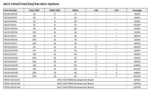
Tabelle mit MCU Optionen MCX C04x/C14x/24x/44x
MCX C04x/C14x/24x/44x MCU Options Part Number Flash (KB) SRAM (KB) GPIOs USB LCD Package MCXC041VFG 32 2 14 - - 16QFN MCXC041VFK 32 2 22 - - 24QFN MCXC141VFM 32 8 28 - - 32QFN MCXC141VLH 32 8 54 - - 64LQFP
in „Bauteil-Roundup: Drohnenkit bis Piezoputzanlage“ · Mikrocontroller und Digitale Elektronik · · Screenshots
-
PDF
Choosing_the_Correct_Digipot-Analog.pdf
5.5 I C 5, 10, 80 35 LFCSP-8 0.68 8% R-tol; 2.3 V supply operation, low power consumption AD5113 New 64 5.5 Up/down 5, 10, 80 35 LFCSP-8 0.68 8% R-tol; tempco is 5 ppm/°C in potentiometer mode AD5116 New 64
in „Alter Analogverstärker mit Digitalpotis ausstatten“ · Mikrocontroller und Digitale Elektronik ·
