-
Datei
Arduino_wdt.h
|| defined(WDP3) /** \ingroup avr_watchdog See \c WDTO_15MS Note: This is only available on the ATtiny2313, ATtiny24, ATtiny44, ATtiny84, ATtiny84A, ATtiny25, ATtiny45, ATtiny85, ATtiny261, ATtiny461, ATtiny861, ATmega48, ATmega88, ATmega168, ATmega48P, ATmega88P, ATmega168P, ATmega328P, ATmega164P,
in „aktuelle AVR µC - wdt.h - kein RAMPD / CTRL / Enable Bit“ · Mikrocontroller und Digitale Elektronik ·
-
Datei
sender.c
Fehlerberechnung #define BAUD_ERROR ((BAUD_REAL*1000)/BAUD) void timer1_init (void) { #if defined (__AVR_ATtiny45__) || defined (__AVR_ATtiny85__) // ATtiny45 / ATtiny85: OCR1C = (F_CPU / F_INTERRUPTS / 4) - 1; // compare value: 1/15000 of CPU frequency, presc = 4 TCCR1 = (1 << CTC1) | (1 << CS11) | (1 << CS10
in „16bit Zeichen über SPI übertragen“ · Mikrocontroller und Digitale Elektronik ·
-
Datei
tn85def.inc
" ;* Title : Register/Bit Definitions for the ATtiny85 ;* Date : 2007-02-28 ;* Version : 2.24 ;* Support E-mail : avr@atmel.com ;* Target MCU : ATtiny85 ;* ;* DESCRIPTION ;* When including this file in the assembly program file, all I/O register ;* names
in „Peter Danneggers Bootloader (fastboot) für AVR-GCC-Toolchain“ · Projekte & Code ·
-
Datei
tn85def.inc
" ;* Title : Register/Bit Definitions for the ATtiny85 ;* Date : 2009-12-11 ;* Version : 2.35 ;* Support E-mail : avr@atmel.com ;* Target MCU : ATtiny85 ;* ;* DESCRIPTION ;* When including this file in the assembly program file, all I/O register ;* names
in „LCD über nur einen IO-Pin ansteuern“ · Projekte & Code ·
-
PDF
Funksteckdosen-1.pdf
Zunächst schließe ich das Empfangsmodul aneine elektrische Quelle von 5 V an; dazu benutze ich meine Attiny-Platine (http://www.g-heinrichs.de/wordpress/index.php/attiny/). Die beiden Data-Ausgänge unterscheiden sich nicht in ihrerFunktion; einendavon schließe ich an Kanal 0 meines Logik-Analysators an;
in „Auseinandergenommene Geräte“ · Analoge Elektronik und Schaltungstechnik ·
-
PDF
Teileliste-04-18-2233.pdf
Mikrocontroller ATMega AVR RISC, 32 KB, 16 Mhz PDIP-40 ATMEGA 32-16 DIP 2 2,99 EUR 1,05 EUR 46 Mikrocontroller ATTiny AVR RISC, 1 KB, 4 Mhz PDIP-8 ATTINY 12L DIP 3 0,99 EUR 0,35 EUR 47 Mikrocontroller MSP430F2001 DIP-Gehäuse 2 0,40 EUR 48 Ethernet-Controller ENC 28J60 DIL-28 3 1,00 EUR 49 Schmitt-Trigger DM74121N
in „Bauelemente abzugeben“ · Markt ·
-
PDF
Teileliste-04-19-1539.pdf
Mikrocontroller ATMega AVR RISC, 32 KB, 16 Mhz PDIP-40 ATMEGA 32-16 DIP 2 2,99 EUR 1,05 EUR 46 Mikrocontroller ATTiny AVR RISC, 1 KB, 4 Mhz PDIP-8 ATTINY 12L DIP 3 0,99 EUR 0,35 EUR 47 Mikrocontroller MSP430F2001 DIP-Gehäuse 2 0,40 EUR 48 Ethernet-Controller ENC 28J60 DIL-28 3 1,00 EUR 49 Schmitt-Trigger DM74121N
in „Bauelemente abzugeben“ · Markt ·
-
PDF
Teileliste-04-19-1957.pdf
Mikrocontroller ATMega AVR RISC, 32 KB, 16 Mhz PDIP-40 ATMEGA 32-16 DIP 0 2,99 EUR 1,05 EUR 46 Mikrocontroller ATTiny AVR RISC, 1 KB, 4 Mhz PDIP-8 ATTINY 12L DIP 0 0,99 EUR 0,35 EUR 47 Mikrocontroller MSP430F2001 DIP-Gehäuse 2 0,40 EUR 48 Ethernet-Controller ENC 28J60 DIL-28 3 1,00 EUR 49 Schmitt-Trigger DM74121N
in „Bauelemente abzugeben“ · Markt ·
-
PDF
Teileliste-04-20-1111.pdf
Mikrocontroller ATMega AVR RISC, 32 KB, 16 Mhz PDIP-40 ATMEGA 32-16 DIP 0 2,99 EUR 1,05 EUR 46 Mikrocontroller ATTiny AVR RISC, 1 KB, 4 Mhz PDIP-8 ATTINY 12L DIP 0 0,99 EUR 0,35 EUR 47 Mikrocontroller MSP430F2001 DIP-Gehäuse 2 0,40 EUR 48 Ethernet-Controller ENC 28J60 DIL-28 3 1,00 EUR 49 Schmitt-Trigger DM74121N
in „Bauelemente abzugeben“ · Markt ·
-
Datei
irsndconfig.h
ATmegas supporting OC0, e.g. ATmega162 * IRSND_OC0A = OC0A on ATmegas/ATtinys supporting OC0A, e.g. ATtiny84, ATtiny85, ATtiny87/167 * IRSND_OC0B = OC0B on ATmegas/ATtinys supporting OC0B, e.g. ATtiny84, ATtiny85 *------------------------------------------------------------------------------------------
in „IRMP - Infrared Multi Protocol Decoder“ · Projekte & Code ·
-
Datei
irsndconfig.h
ATmegas supporting OC0, e.g. ATmega162 * IRSND_OC0A = OC0A on ATmegas/ATtinys supporting OC0A, e.g. ATtiny84, ATtiny85, ATtiny87/167 * IRSND_OC0B = OC0B on ATmegas/ATtinys supporting OC0B, e.g. ATtiny84, ATtiny85 *------------------------------------------------------------------------------------------
in „IR Signal falsch“ · Mikrocontroller und Digitale Elektronik ·
-
PDF
kicad_8450_dcm_liste_neu_v3.pdf
QFN/MLF20, 4k Flash, 256B SRAM, 256B EEPROM, dW ATTINY44A-PU PDIP14, 4k Flash, 256B SRAM, 256B EEPROM, dW ATTINY44A-SSU SO14, 4k Flash, 256B SRAM, 256B EEPROM, dW ATTINY45-20MU ATTINY25, QFN/MLF20, 4k Flash, 256B SRAM, 256B EEPROM, Debug Wire ATTINY45-
in „KiCAD Eeschema, Bibliotheksdokumentation *.dcm als PDF-Datei“ · Platinen ·
-
Datei
irsndconfig.h
----------------------------------------------------------------------------------- * AVR ATMega/ATTiny section: * * Change hardware pin here: IRSND_OC2 = OC2 on ATmegas supporting OC2, e.g. ATmega8 * IRSND_OC2A = OC2A on ATmegas supporting OC2A, e.g. ATmega88 * IRSND_OC2B = OC2B on ATmegas supporting
in „IRMP - Infrared Multi Protocol Decoder“ · Projekte & Code ·
-
PDF
Arduino.pdf
AVR_ATmega2560__) ADMUX = _BV(REFS0) | _BV(MUX4) | _BV(MUX3) | _BV(MUX2) | _BV(MUX1); #elif defined (__AVR_ATtiny24__) || defined(__AVR_ATtiny44__) || defined(__AVR_ATtiny84__) ADMUX = _BV(MUX5) | _BV(MUX0); #elif defined (__AVR_ATtiny25__) || defined(__AVR_ATtiny45__) || defined(__AVR_ATtiny85__) ADMUX = _BV(
in „Aref Spannung, was ist besser?“ · Mikrocontroller und Digitale Elektronik ·
-
Datei
io.h
<avr/iotn13a.h> #elif defined (__AVR_ATtiny25__) # include <avr/iotn25.h> #elif defined (__AVR_ATtiny4313__) # include <avr/iotn4313.h> #elif defined (__AVR_ATtiny45__) # include <avr/iotn45.h> #elif defined (__AVR_ATtiny85__) # include <avr/iotn85.h> #elif defined (__AVR_ATtiny24__) # include <avr/iotn24.h> #elif defined (__AVR_ATtiny24A__) # include <avr/iotn24a.h> #elif defined (__AVR_ATtiny44__) # include <avr/iotn44.h> #elif defined (__AVR_ATtiny44A
in „direkt in ein Register des Tiny5 schreiben“ · Mikrocontroller und Digitale Elektronik ·
-
Datei
VirtualWire.cpp
defined #endif #include "VirtualWire.h" #include <util/crc16.h> #undef TIMER_VECTOR #ifdef __AVR_ATtiny85__ # define TIMER_VECTOR TIM0_COMPA_vect #elif defined(__AVR_ATtiny84__) || defined(__AVR_ATtiny24__) || defined(__AVR_ATtiny44__) // Why can't Atmel make consistent? # define TIMER_VECTOR TIM1_COMPA_vect
in „Korrigierte "VirtualWire" Library für Attiny84 / 85“ · Projekte & Code ·
-
Datei
irsndconfig.h
----------------------------------------------------------------------------------- * AVR ATMega/ATTiny section: * * Change hardware pin here: IRSND_OC2 = OC2 on ATmegas supporting OC2, e.g. ATmega8 * IRSND_OC2A = OC2A on ATmegas supporting OC2A, e.g. ATmega88 * IRSND_OC2B = OC2B on ATmegas supporting
in „Umfrage: welche IR-Protokolle nutzt ihr mit IRMP?“ · PC Hard- und Software ·
-
PDF
ATT5FCA9.pdf
STK501 ATtiny25 AT90S4433 ATmega161 ATmega640 STK503 AT90CAN128 STK501 ATtiny26 AT90S4434 ATmega162 ATmega644 AT90PWM2 STK520 ATtiny28 AT90S8515 ATmega163 ATmega645 STK502 AT90PWM3 STK520 ATtiny4STK505 AT90S8535 ATmega164P ATmega649 STK502 AT90USB646 STK525 ATtiny45 ATmega8 ATmega165 STK502 ATmega2560 STK503 AT90USB647 STK525 ATtiny84 ATmega16 ATmega165P STK502 ATmega2561 STK501 AT90USB1286 STK525 ATtiny85 ATmega32 ATmega168 ATmega3250 STK504 AT90USB1287 STK525
in „Angebot STK500+STK501+JTAGICE“ · Mikrocontroller und Digitale Elektronik ·
-
Datei
irsndconfig.h
----------------------------------------------------------------------------------- * AVR ATMega/ATTiny section: * * Change hardware pin here: IRSND_OC2 = OC2 on ATmegas supporting OC2, e.g. ATmega8 * IRSND_OC2A = OC2A on ATmegas supporting OC2A, e.g. ATmega88 * IRSND_OC2B = OC2B on ATmegas supporting
in „IRSND Daten für Roomba“ · Mikrocontroller und Digitale Elektronik ·
-
Datei
irsndconfig.h
----------------------------------------------------------------------------------- * AVR ATMega/ATTiny section: * * Change hardware pin here: IRSND_OC2 = OC2 on ATmegas supporting OC2, e.g. ATmega8 * IRSND_OC2A = OC2A on ATmegas supporting OC2A, e.g. ATmega88 * IRSND_OC2B = OC2B on ATmegas supporting
in „IR Fernbedienung mit IRSND“ · Mikrocontroller und Digitale Elektronik ·
-
Datei
Fernbedienung_FB9_Tiny4313.c
/* * Fernbedienung_FB9_Tiny4313.c * * Created: 04.08.2020 19:08:49 * Author: Andreas * * ATtiny 4313 * F_CPU global auf 8MHz gesetzt; wie das geht s. Screenshot im Ordner* * * Eingänge/ Taster * PB0 (PCINT0) -> Taste Vol- * PB1 (PCINT1) -> Taste Vol+ * PD2 (PCINT2) -> Power * PD3 (PCINT3) ->
in „IR Fernbedienung mit IRSND“ · Mikrocontroller und Digitale Elektronik ·
-
Datei
irsndconfig.h
----------------------------------------------------------------------------------- * AVR ATMega/ATTiny section: * * Change hardware pin here: IRSND_OC2 = OC2 on ATmegas supporting OC2, e.g. ATmega8 * IRSND_OC2A = OC2A on ATmegas supporting OC2A, e.g. ATmega88 * IRSND_OC2B = OC2B on ATmegas supporting
in „IRMP - Infrared Multi Protocol Decoder“ · Projekte & Code ·
-
 Bild
Bild
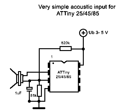
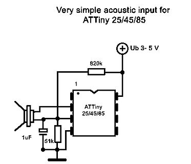
Schaltplan für akustischen Eingang mit ATTiny
Very simple acoustic input for ATTiny 25/45/85 Ub 3- 5 V 820k 1 uF 51k ATTiny 25/45/85
in „Feinfühlige Geräuscherkennung mit Arduino?“ · Mikrocontroller und Digitale Elektronik · · Schaltpläne
-
PDF
ATTiny1624.pdf
ATtiny1624/1626/1627 Product Brief Introduction The ATtiny1624/1626/1627 microcontrollers of the tinyAVR 2 family are using the AVR CPU with hardware multiplier, running at up to 20 MHz, with 16 KB Flash,
in „Neues Produkt AtTiny1624“ · Mikrocontroller und Digitale Elektronik ·
-
Datei
USI_TWI_Master.h
Supported devices : All device with USI module can be used. * The example is written for the ATmega169, ATtiny26 and ATtiny2313 * * AppNote : AVR310 - Using the USI module as a TWI Master * * Description : This is an implementation of an TWI master using * the USI module as basis. The implementation assumes
in „I2C ATtiny167 mit USI“ · Mikrocontroller und Digitale Elektronik ·
-
PDF
avr-typen.pdf
10 1 ja 0,25 256 ja 1,8..5,5 1,8..5,5 2 5 0 6 nein 8 20 8 8 ATtiny85 8 0,5 512 8 20 8 4er-Serie ATtiny24 2 0,12 128 14 20 14 ATtiny24A 2 0,12 128 14 20 15 20 14 ATtiny44 4 0,25 256 14 20 14 ATtiny44A 4 20 12 12 1 1 0 8 10 1 ja 0,25 256 ja 1,8..5,5 1,8..5,5 2 4 1 4 nein 14 20 15 20 14 ATtiny84 8 0,5 512 14 20 14 ATtiny84A 8 0,5 512 14 20 15 20 14 6er-Serie ATtiny26 2 16 nein 0,12 128 nein 2,7..5,5 2,7..5,5 3 0 4 20 32 20 ATtiny261 2 20 ja 0,12 128 ja 1,8..5,5 1,8..5,5 6 1 6 20 32 20 ATtiny261A
-
Datei
USI_TWI_Master.h
Supported devices : All device with USI module can be used. * The example is written for the ATmega169, ATtiny26 and ATtiny2313 * * AppNote : AVR310 - Using the USI module as a TWI Master * * Description : This is an implementation of an TWI master using * the USI module as basis. The implementation assumes
in „Hilfe! Mein AVR USI Master (I2C) mag nicht mehr :(“ · Mikrocontroller und Digitale Elektronik ·
-
Datei
avr.h
crts8535.o%s} \ %{mmcu=at86rf401:crt86401.o%s} \ %{mmcu=attiny13:crttn13.o%s} \ %{mmcu=attiny2313:crttn2313.o%s} \ %{mmcu=attiny24:crttn24.o%s} \ %{mmcu=attiny44:crttn44.o%s} \ %{mmcu=attiny84:crttn84.o%s} \ %{mmcu=attiny25:crttn25.o%s} \ %{mmcu=attiny45:crttn45.o%s} \ %{mmcu=attiny85:crttn85.o%s} \ %{mmcu=attiny261:crttn261.o%s} \ %{mmcu=attiny461:crttn461.o%s} \ %{mmcu=attiny861:crttn861.o%s} \ %{mmcu=atmega103|mmcu=avr3:crtm103.o%s} \ %{mmcu=atmega603:crtm603.o%s} \ %{mmcu=
in „ATtiny24 - ISR wird nie gerufen __vectors> fehlt“ · Mikrocontroller und Digitale Elektronik ·
-
Datei
Fernbedienung_FB9_Tiny4313.c
/* * Fernbedienung_FB9_Tiny4313.c * * Created: 04.08.2020 19:08:49 * Author: Andreas * * ATtiny 4313 * F_CPU global auf 8MHz gesetzt; wie das geht s. Screenshot im Ordner* * * Eingänge/ Taster * PB0 (PCINT0) -> Taste Vol- * PB1 (PCINT1) -> Taste Vol+ * PB2 (PCINT2) -> Power * PB3 (PCINT3) ->
in „IR Fernbedienung mit IRSND“ · Mikrocontroller und Digitale Elektronik ·
-
Datei
irsnd-main-avr.c
additions from m.schoeldgen@hotmail.com * $Id: irsnd-main-avr.c,v 1.3 2016/09/09 08:01:11 fm Exp $ * * ATTINY2313 @ 8 MHz internal RC Osc with BODLEVEL 4.3V: lfuse: 0xE2 hfuse: 0xDC efuse: 0xF9 * * This program is free software; you can redistribute it and/or modify * it under the terms of the GNU General
in „Konzeption einer IR Fernbedienung“ · Mikrocontroller und Digitale Elektronik ·
-
Datei
examples.c
: %k", 28123); Ausgabe: 28.123 %c : Ausgabe als Asciizeichen MCU : ATmega8, ATmega48 - ATmega328 ATtiny2313, ATtiny4313 ATtiny24 - ATtiny44 ATtiny25 - ATtiny85 16.02.2019 R. Seelig ---------------------------------------------------------- */ #include <string.h> #include <util/delay.h> #include <avr/
in „Ausgabe mittels printf über UART für ATmega / ATtiny“ · Projekte & Code ·
-
Datei
USI_TWI_Master.h
Supported devices : All device with USI module can be used. * The example is written for the ATmega169, ATtiny26 and ATtiny2313 * * AppNote : AVR310 - Using the USI module as a TWI Master * * Description : This is an implementation of an TWI master using * the USI module as basis. The implementation assumes
in „TWI mit USI nach AN-310“ · Mikrocontroller und Digitale Elektronik ·
-
Datei
main.c
prj271/index.html http://www.technoblogy.com/show?KX0 ADC: https://www.marcelpost.com/wiki/index.php/ATtiny85_ADC Save Power: https://elektro.turanis.de/html/prj271/index.html Timer normal Mode with Interrupt https://www.gadgetronicx.com/attiny85-timer-tutorial-generating-time-delay-interrupts/ https://wolles-elektronikkiste.de/timer-und-pwm-teil-1 Timer compare Mode with Interrupt https://www.gadgetronicx.com/attiny85-compare-match-tutorial-interrupts/ */ #define F_CPU 1000000UL typedef enum { false, true} bool; #define LED_Vcc_Warning PB4 // PIN3 - PB4 - LED_Vcc_Warning red --> output #define LED_Christmas_Star
in „Attiny85 ADC Eingangswiderstand - wie hoch“ · Mikrocontroller und Digitale Elektronik ·
-
Datei
irsnd-main-avr.c
additions from m.schoeldgen@hotmail.com * $Id: irsnd-main-avr.c,v 1.3 2016/09/09 08:01:11 fm Exp $ * * ATTINY2313 @ 8 MHz internal RC Osc with BODLEVEL 4.3V: lfuse: 0xE2 hfuse: 0xDC efuse: 0xF9 * * This program is free software; you can redistribute it and/or modify * it under the terms of the GNU General
in „IR Fernbedienung mit IRSND“ · Mikrocontroller und Digitale Elektronik ·
-
PDF
avr8-gnu-toolchain-3.4.0.663-readme.pdf
which are newly supported in this release are marked with * at90s2313 at90s2323 at90s2333 at90s2343 attiny22 at90s4414 at90s4433 at90s4434 at90s8515 at90c8534 ata5272* ata5505* ata5790* ata5795* ata6285* ata6286* ata6289 attiny13 attiny13a attiny2313 attiny2313a attiny24a attiny4313 attiny44 attiny44a attiny828* attiny84 attiny25 attiny45 attiny85 attiny261 attiny261a attiny461a attiny861 attiny861a attiny43u attiny87 attiny88 at86rf401 at43usb355 at76c711 atmega103 at90usb82 at90usb162 atmega8u2 atmega16u2 atmega32u2
in „ATtiny10 ISR TIM0_COMPB_vect“ · Mikrocontroller und Digitale Elektronik ·
-
Datei
USI_TWI_Master.h
Supported devices : All device with USI module can be used. * The example is written for the ATmega169, ATtiny26 and ATtiny2313 * * AppNote : AVR310 - Using the USI module as a TWI Master * * Description : This is an implementation of an TWI master using * the USI module as basis. The implementation assumes
in „C-Code optimieren (passt nicht in Attiny2313) :(“ · Mikrocontroller und Digitale Elektronik ·
-
Datei
USI_TWI_Master.h
Supported devices : All device with USI module can be used. * The example is written for the ATmega169, ATtiny26 and ATtiny2313 * * AppNote : AVR310 - Using the USI module as a TWI Master * * Description : This is an implementation of an TWI master using * the USI module as basis. The implementation assumes
in „Attiny 2313A - ROM am Limit? Probleme mit Optimierer“ · Mikrocontroller und Digitale Elektronik ·
-
Datei
USI_TWI_Master.h
Supported devices : All device with USI module can be used. * The example is written for the ATmega169, ATtiny26 and ATtiny2313 * * AppNote : AVR310 - Using the USI module as a TWI Master * * Description : This is an implementation of an TWI master using * the USI module as basis. The implementation assumes
in „Attiny 2313A - ROM am Limit? Probleme mit Optimierer“ · Mikrocontroller und Digitale Elektronik ·
-
 Bild
Bild
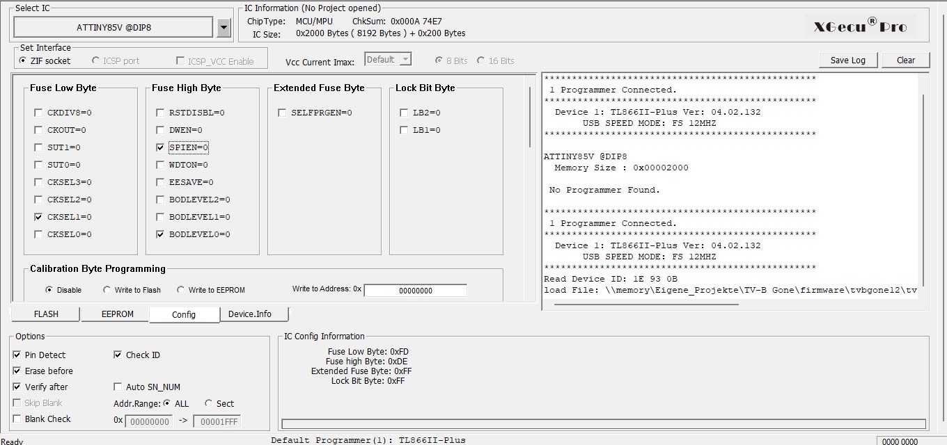
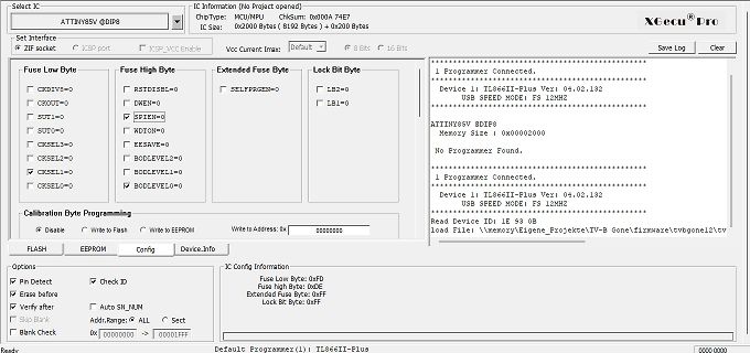
Softwareoberfläche eines Xecoo Pro Programmiergeräts
Xecoo Pro ATTINY85V @DIP8 IC Information (No Project opened) ChipType: MCU/MPU ChkSum: 0x000A 74E7 IC Size: 0x2000 Bytes (8192 Bytes) + 0x200 Bytes Set Interface ZIF socket ICSP port ICSP_VCC Enable Vcc Current Imax
in „TV B Gone: Erst nach 45 Minuten den TV ausschalten -> Brauche Hilfe“ · Mikrocontroller und Digitale Elektronik · · Screenshots
-
Datei
asl_unterstuetzte_prozessoren.txt
AT90S4434 AT90S8515 AT90C8534 AT90S8535 AT90USB646 AT90USB647 AT90USB1286 AT90USB1287 AT43USB355 ATTINY4 ATTINY5 ATTINY9 ATTINY10 ATTINY11 ATTINY12 ATTINY13 ATTINY13A ATTINY15 ATTINY20 ATTINY24 ATTINY24A ATTINY25 ATTINY26 ATTINY28 ATTINY40 ATTINY44 ATTINY44A ATTINY45 ATTINY48 ATTINY84 ATTINY84A ATTINY85 ATTINY87 ATTINY88 ATTINY102 ATTINY104 ATTINY167 ATTINY261 ATTINY261A ATTINY43U ATTINY441 ATTINY461 ATTINY461A ATTINY828 ATTINY841 ATTINY861 ATTINY861A ATTINY1634 ATTINY2313 ATTINY2313A ATTINY4313 ATMEGA48
in „gas as a68 m68k - was nimmt man ?“ · Mikrocontroller und Digitale Elektronik ·
-
PDF
Tiny_AVR_2_Family.pdf
. c ni g A c l E R i / 2 r m n n e 6 v h i 2 s o o S a F E S P I 1 P A A I R 1 E C W 3 O C L U P ATTINY1627 16 256 2 048 24 22 1 (15) 1 1 1 3 6 Y 1 1 (4) 2/1/1 VQFN ATTINY1626 16 256 2 048 20 18 1 (15) 1 1 1 3 6 Y 1 1 (4) 2/1/1 VQFN, SOIC, SSOP ATTINY1624 16 256 2 048 14 12 1 (9) 1 1 1 3 6 Y 1 1 (4)
in „Neue 8-Bit Tinys vorgestellt: 417/814/816/817“ · Mikrocontroller und Digitale Elektronik ·
-
Datei
USI_TWI_Master.h
Supported devices : All device with USI module can be used. * The example is written for the ATmega169, ATtiny26 and ATtiny2313 * * AppNote : AVR310 - Using the USI module as a TWI Master * * Description : This is an implementation of an TWI master using * the USI module as basis. The implementation assumes
in „Butterfly USI als TWI Master verwenden“ · Mikrocontroller und Digitale Elektronik ·
-
Datei
160102_ADC_Konfig.txt
Atmel Studio 7.0 ATTiny85 ________ #define F_CPU 1000000 // int.Takt auf 1MHz gestellt #include <avr/io.h> #include <util/delay.h> #define OBER_BEREICH (4*1023/5) #define MITTEL_BEREICH (OBER_BEREICH - UNTER_BEREICH) #define
in „ADC initialisieren, Grundlagen“ · Mikrocontroller und Digitale Elektronik ·
-
PDF
pbwake.pdf
3W C2 100n GND 8 C C 2 5 V Q1 PB0 1 6 PB1 IRF530 7 PB2 3 2 U1 R2 PB3 10k 3 PB4 Microcontroller 1 ATTiny-13 RESET/PB5 ATTiny-25 ATTiny-45 C N ATTiny-85 C R 0 G (ATMega-328P different pinout) 1 4 GND GND J3 1 V DEBUG + GND Michael Buesch <m@bues.ch> Sheet: / D File: pbwake.sch D Title: pbwake Size: A4
in „Powerbank-Wecker für neue ANKER Powerbank“ · Analoge Elektronik und Schaltungstechnik ·
-
Datei
main.c
/* Beeps Fuses LHE C2 DD FF Von da kommen wir: + -------o------------------------------. | | ATtiny85 | _____|______ | | Vcc | | .-------------------| PB5/Reset | | | .-------------| PB2 PB1|---. === | | .-------| PB3 | #< Lautsprecher | o o o o-| PB4 PB0|---' | | | | | |____________| | o o o o GND
in „Alarmton/Buzzer-Dreiklang erzeugen“ · Analoge Elektronik und Schaltungstechnik ·
-
Datei
USI_TWI_Master.h
Supported devices : All device with USI module can be used. * The example is written for the ATmega169, ATtiny26 and ATtiny2313 * * AppNote : AVR310 - Using the USI module as a TWI Master * * Description : This is an implementation of an TWI master using * the USI module as basis. The implementation assumes
in „Atmel AVR TWI Library - Verständnisfrage zu Pointer“ · Mikrocontroller und Digitale Elektronik ·
-
PDF
Grillen_Fuchs_Beschreibung_V1_0.pdf
PB1-Pin einfach offen. DerATTINY wird in den Pausen zwischen dem Senden immer in den Power-Down-Modus versetzt. Die Stromaufnahme der gesamten Schaltung beträgt dann etwa 5uA. Wenn im Code das #define PAUSE vergrößert wird, so kann
in „ATTINY 433MHz Fuchssender mit akustischem Grillen-Sound“ · Projekte & Code ·
-
PDF
Grillen_Fuchs_Beschreibung_V1_1.pdf
PB1-Pin einfach offen. DerATTINY wird in den Pausen zwischen dem Senden immer in den Power-Down-Modus versetzt. Die Stromaufnahme der gesamten Schaltung beträgt dann etwa 5uA. Wenn im Code das #define PAUSE vergrößert wird, so kann
in „ATTINY 433MHz Fuchssender mit akustischem Grillen-Sound“ · Projekte & Code ·
-
Datei
device.c
}, { "ATtiny84", 4096, 0x60, 512, 512, DF_NO_MUL|DF_NO_JMP|DF_NO_ELPM|DF_NO_ESPM|DF_NO_EICALL|DF_NO_EIJMP}, { "ATtiny85", 4096, 0x60, 512, 512, DF_NO_MUL|DF_NO_JMP|DF_NO_ELPM|DF_NO_ESPM|DF_NO_EICALL|DF_NO_EIJMP
in „AVR-ChipBasic2 - BASIC-Computer mit ATMega 644“ · Projekte & Code ·
-
Datei
device.c
}, { "ATtiny84", 4096, 0x60, 512, 512, DF_NO_MUL|DF_NO_JMP|DF_NO_ELPM|DF_NO_ESPM|DF_NO_EICALL|DF_NO_EIJMP}, { "ATtiny85", 4096, 0x60, 512, 512, DF_NO_MUL|DF_NO_JMP|DF_NO_ELPM|DF_NO_ESPM|DF_NO_EICALL|DF_NO_EIJMP