AMPERE DARLINGTON ÎÎÎÎÎCollector–Emitter Voltage V 60 ÎÎ80 Vdc CEO POWER TRANSISTORS ÎÎÎÎÎCollector–Base Voltage V 60 ÎÎ80 Vdc COMPLEMENTARY CB ÎÎÎÎÎEmitter–Base Voltage V 5.0 ÎÎÎ Vdc SILICON EB 60–80 VOLTS ÎÎÎÎÎCollector Current ÎÎ I 10 Adc C 150 WATTS ÎÎÎÎÎBase CurrentÎÎÎÎÎ ÎÎ I 0.2 Adc B ÎÎÎÎÎTotal
einwandfrei. https://github.com/EBiCS/BAFANG_GD32F303RCT6/blob/3656278eaa890d3de8aa06337c73ab4e6a93c21c/src/main.c#L578 Ich habe derzeit keine Idee, ob da analoge Hardware über irgendeine Zeitkonsante per Widerstand + Kondensator in die Suppe spuckt, oder doch noch ein Pin des Prozessors anders gesetzt
Transistor der diese Spannung schaltet, habe ich auf der Platine identifiziert, die Spannung an der Base fällt mit der originalen Firmware auf 4,3V, bei mir bleibt sie auf 5V :-( Hat noch jemand einen Tipp, was ich noch probieren könnte?! Die Original-Firmware ist hier zu finden: https://github.com
sich um ein aktives Bauteil. Es reagiert eindeutig auf eine Ansteuerung des ersten Pins (vermutlich Base bei BJT oder Gate bei MOSFET). Ich habe ein LCR-Meter zwischen Emitter und Kollektor (bzw. Source und Drain) angeschlossen. Mein LCR-Meter kann Widerstände bis 200 MΩ messen. Anfangszustand: Anzeige „OL“ Bei leichter Ansteuerung des Base-/Gate-Pins (kurzes Antasten): → ca. 50 MΩ zwischen E und C Das beobachtete Verhalten entspricht dabei eher einem Transistor als einem MOSFET. Da ich solche Analysen normalerweise schrittweise
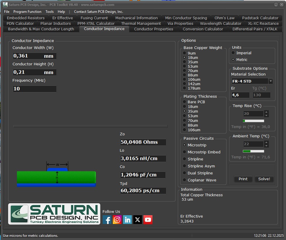
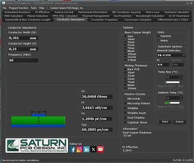
Program Function Tools Help Conductor Impedance Conductor Width (W) 0,361 mm Conductor Height (H) 0,21 mm Frequency (MHz) 10 Zo 50,0408 Ohms Lo 3,0165 nH/cm Co 1,2046 pF/cm Tpd 60,2805 ps/cm Options Units Base Copper Weight 9um Imperial 18um Metric 35um 53um 70um 80um 106um 142um 178um Substrate Options
current (full cycle,jTnitial = 25°C)F = 60 Hz t = 16.7 ms 63 A I t I t Value for fusing tp= 10 ms 21 A²s dI/dt Critical rate of rise of on-state cuF = 120 Hz T = 125°C 50 A/µs rent G = 2 x GT , r ≤ 100 ns j GM Peak gate current tp= 20 µs T j 125°C 4 A P Average gate power dissipation T = 125°C 1 W G
the The Bode plot of the loop gain, the compensator gain and the minimum voltage buffer. Figure 21 shows the charge current power stage gain is shown in Figure 21. control loop. Adapter Current Limit Control Loop The compensation capacitor (C ICOMP ) gives the error amplifier (GMI) a pole at a very
electronic Smaller than your thumb, it includes all essential networking features, including a 10Base- device T/100Base-TX Ethernet connection, proven operating system, an embedded web server, e-mail • Remote command and control of edge alerts, a full TCP/IP protocol stack and 256-bit AES encryption
...................................................................................................21 5F Préparation de la solution de gravure................................................................................21 5.1F Acide chlorhydrique et oxygène atmosphérique....................................................................................21 5.2F Acide chlorhydrique et peroxyde...........................................................................................................22 5.3F Electrolyse.....................................
Programming Counter (PC) and Stack......................................................................21 2 Reset ...................................................................................................................................26 2.1 Power on Reset (POR) ................................
with 4 interrupt interval time options - IDLE mode wake-up timer or used as one simple 15-bit time base - Clock source: Slow-clock, Fsys/128, or FIRC/512 (16 MHz/512) 9. Interrupt Three External Interrupt pins - 1 pin is falling edge wake-up triggered & Interrupts - 2 pins are rising or falling edge
-0000) Searchlight base should be mounted on level, flat surface. Using the light base mounting template Select a location near the helm which will allow for convenient operation of control. enclosed, drill three (3) mounting
ein -1 gegeben hat darf gerne mal erklären warum. manch Nutzer hat sich hier eine solide "Fan"base aufgebaut. Die geben dann immer -1, sobald der Name auftaucht, egal was dabei geschrieben wurde. Am besten einfach ignorieren.
Es gab da mal einen Test verschiedener 30mA Fi, die haben bei durchschnittlich 21mA ausgelöst (manch einer auch 15 oder knapp unter 30mA) und das hat deren Angeben nach etwa 20-25ms gedauert. Flip B. schrieb im Beitrag #7965086: > Auch mit normalem Schuhwerk mit plastiksohle kommt
Base64 U. schrieb im Beitrag #7964175: > Alternativ Labornetzteil nehmen, 1A durch schicken und die Spannung an > der Zündspule messen und zurück rechnen. Dabei solltest Du (Volker) aber bedenken
slightly different angle differing by Da ¼ Dx=f. ered. In order to reduce the cost, an individual base plate 0 This means that two rays differing by Dk can be related to such as a wooden board (e.g., MDF, 25 mm thick and 4 Da using the formula describing the diffraction maxima for 600 450 mm side length
bestimmt sind. 6 1. Schließen Sie alle externen Geräte an, etwa Port-Replicator, Slice-Akku oder Media-Base, und setzen Sie alle Karten ein, etwa eine ExpressCard. 2. Schließen Sie die zuvor getrennten Telefon- und Netzwerkkabel wieder an den Computer an. VORSICHT: Wenn Sie ein Netzwerkkabel anschließen,
Manchester kann man schon mit den nur 35 Befehlen der Base-PICs sehr einfach dekodieren. Oder mit einem Z80 mit einem 1 MHz Takt. Versuchs noch einmal etwas hardwarenäher. Dabei lernst du dann auch, wie man auf die GPIOs z.B. in C zugreifen kann. Für
ein bisschen Code hier im Forum gefunden hat aber er hat leider nicht funktioniert. RC-Switch: ca. 21% TinyRF: ca. 9%
Fotos vom kompletten Innenleben und mache einige Messungen. Zeige aber wo du misst. Fange an den Basen der Leistungstransistoren an. Hast du schon eine ausführliche Sichtkontrolle durchgeführt? Du hast ja 2 identische NTs. Da könnte man zumindest versuchen Vergleichsmessungen zu machen, auch wenn
Christoph M. schrieb im Beitrag #7953423: > self.sm = rp2.StateMachine(sm_id, pulse_counter, in_base=pin) Wenn du mit PIO-JMP arbeitest, dann auch in der StateMachine Instanziierung darauf hinweisen. [code]#!python self.sm = rp2.StateMachine(sm_id, pulse_counter, in_base=pin, jmp_pin=pin) [/code
späteren Tanz mit 2³². >Der Rest ist Zyklen zählen. Super Tipps. Die nehme ich in meine "Knowledge Base" a.k. Hirn auf.
Graphische Ausgabemöglichkeiten waren damals noch > ziemlich unerschwinglich. AAcircuit wurde im 21. Jahrhundert entwickelt.
Entstörmaßnahmen fehlen hier allesamt - Vorschläge sind gerne willkommen (z.B. kleines C von T1-Base nach GND? oder noch ein Haufen TVS von T1-Base in alle Himmelsrichtungen?). Soweit mein Vorschlag. Viele Grüße Igel1
2 screws ( ). (Fig. 7) DIGITAL P.C.B. b. Remove screw ( ) and screw ( ). (Fig. 6) c. Disconnect CB21, CB22, CB23, CB64 and CB65. (Fig. 6) d. Remove the DIGITAL P.C.B. which is connected directly to the FUNCTION (6) P.C.B. with board-to-board connectors. (Fig. 6) CB64 CB65 CB22 CB23 CB21 4. DIGITAL P.C.B
Brahms Wiegenlied) "Keyboard Cat " // 19 Keyboard cat "MII Channel " // 20 MII Channel "Greenhill " // 21 Greenhill "Song of Storms" // 22 Song of storms "Minuet in G " // 23 Minuet in G "Pulo da gaita " // 24 Pulo da gaita "Badinerie " // 25 Badinerie "Baby elephant " // 26 Empty "Cannon in D " // 27 Cannon
request and will send you a personal response shortly. Please also take a look at our Nero knowledge base with a lot of useful information about the software and current issues..." Bis heute keine Antwort. ciao gustav
völlig normal, egal was man ansonsten von gustav hält. Der Dateiname (ohne Pfad) scheint "30Nov21_ 173636.wmv (Einfügen f..." zu heißen. Das riecht streng danach, als ob "gustav" an den kompletten Dateinamen noch einen Kommentar angehängt hat.
Automotive Grade Linux (18%).
While 41% of respondents said that they have no intention of using a base Automotive OS, those who did intend to use one said they are most likely to use AUTOSAR OS (21%), Automotive Grade Linux (13%), and Android Automotive OS (11%).
WHAT IS THE BASE AUTOMOTIVE OS THAT YOUR
significant due to location or extreme height (e.g. cellular length of time (more than microseconds). phone base-station antennae). The equipment Therefore, equipment protection requires a exposure as a result of EPR can be very high, and shunt protector that: 1) can react fast enough to at high earth resistance
Description............................................................................................21 2.6 Measurements Including the Acoustical path......................................................23 2.6.1 Prerequisites.............................................................................
Textterminal mit 96 Zeichen pro Zeile in 25 Zeilen (in einer 9x12-Pixelmatrix war das gerade noch auf einen BAS-Monitor verwendbar). Allerdings: Der einzige Z80, der da überhaupt verwendet wurde, steckte im Graphikterminal.
. BAS-Monitor, nicht Fernseher. Und da ist die Horizontalauflösung nur vom Pixeltakt abhängig (und natürlich der Bandbreite des Videoverstärkers im Monitor). Der Pixeltakt meines Selbstbauterminals betrug
23559-5220 CAP SM 22U 35V AL ELEC C14 23559-6010 CAP SM 1U 50V AL ELEC C86 ,C88-90 25021-1010 DIO SM BAS21 200V/200mA SOT23 D1-7 ,D24 25340-1000 TRAN SM PNP BC859C SOT23 Q5-9 ,Q26 25340-1010 TRAN SM PNP PMBT3906 Q13-14 25377-1000 TRAN SM NPN BC849C SOT23 Q1-2 ,Q10-12, Q18 ,Q24 25381-1000 TRAN SM NPN SMBT3904
zwei > 100poligen Steckverbinder sauber aufs eigene Layout bekommen. Oder ein Waveshare CM4-IO-BASE-B verwenden. https://www.waveshare.com/wiki/CM4-IO-BASE-B Und genau da ist es dann wirklich von Vorteil, GPIO14/15 für die Linux-Console freizuhalten und andere UARTs für die AVRs zu verwenden.
klar? Nicht, daß Du auf die Idee kommst, daraus "auszurechnen", daß die Buchse bei 20 V dann schon 21 A vertragen müsste ...

 Bild
Bild
 Bild
Bild
 Bild
Bild

 Bild
Bild