läuft bei ABB unter 4-Quadrantenmessung... die Silbervariante der ABB Zähler kann das, z.B. ABB B21 312-100
*8h / Selbst bei nur 200W*8h wird mehr erzeugt als verbraucht.) Aus Erfahrung verbrauche ich haber max 1,5kWh am Tag mit meinem Wohnwagen. Falls nun der Campingplatzzähler nicht rücklaufgesperrt ist sehe ich da schon eine gewisse Gefahr! Sebastian R. schrieb im Beitrag #7621635: > Kann es vielleicht
latched at the trigger to assist in point placement. There are three decimation modes: normal, min/max, and hires: H Normal (sub-sample) mode throws away samples between saved sample points. H Min/max mode saves the maximum and minimum samples over the decimation interval. H Hires mode gives extra resolution
gibt nichts an: https://www.exidegroup.com/at/de/battery/1521/printable/pdf Banner hat auch nur eine max. Ladespannung: https://www.bannerbatterien.com/download/?file=4433 Mehr hersteller kenne ich jetzt nicht mehr...
gute KFZ Batterien? Varta. Es gibt kein Varta. "Eine Woche später kaufte Johnson Controls für 312,5 Millionen Euro die 80 % von Varta gehaltenen Anteile an der VB Autobatterie GmbH" "Mit dem Verkauf aller operativen Geschäftsbereiche verabschiedete sich 2007 Varta nach über 100 Jahren ganz aus
163.84mV bis 163.84mV und einen kleineren von -40.96mV bis 40.96mV. Im größeren Bereich hat das LSB 312.5nV (0.3125uV). Damit kannst du theoretisch bis auf weniger als 1mA auflösen. ABER: 1. Auflösung und Genauigkeit werden oft durcheinandergebracht: https://www.mikrocontroller.net/articles/Aufl
es wohl auf ein Neudesign der Strommessung hinauslaufen... Der Messbereicht bleibt weiterhin bei max 30A evtl. später mal bis 50A. Dann ist aber definitiv Schluss. Allerdings brauch ich ne satte Überstromreserve im 200A-Bereich für 1...5s. Wenn es dabei den Messbereich übersteuert ist das kein Problem
Feature Pb Free Solder Process Non-Pb Free Solder Process Average Ramp Up Rate (T to T ) 3°C / second Max. 3°C / Second Max. s p Preheat - Temperature Min (T sin.) 100°C 150°C - Temperature Max (T sax.) 150°C 200°C - Time (tsMin to s Max) 60 to 120 seconds 60 to 120 seconds Time Maintained Above Critical
Depth : 237 mm (9.33'') SOG (Sync On Green) Height : 428 mm (16.85'') -Min Digital 508 mm (19.99'') -Max 3-2. Video Input Signal 1) Type : R, G, B Analog 7. WEIGHT (with SPEAKER) 2) Voltage Level : 0~0.71 V Net. Weight : 8.8kg (19.40 lbs) a) Color 0, 0 : 0 Vp-p Gross Weight : 11.3kg (24.91 lbs) b) Color
PD-97594 IRLR6225PbF ® HEXFET Power MOSFET V 20 V DS R D D DS(on) max 4.0 mΩ (@V GS= 4.5V) R DS(on) max 5.2 S (@V GS= 2.5V) mΩ G G Q g (typical) 48 nC D-Pak S IRLR6225PbF RG (typical) 2.2 Ω D 42 h A G D S Gate Drain Source Applications • Battery Protection Switch Features
. Additional error: +(0.25 % of fuL1-scaLe value + 0.03 %/K) rI External voltage: max. Urr" = L25 V but not exceedin8 U, = 180 V General t- ıigital display: 20-digit fluorescent dispLay (green) 5 x 7 dot matrix, character size 9 x 6.3 m Single-value display: 4 to 5 digits, max. 0 30000 with sign, unit and channel assignment Two-value display: 4 digits, max. 0 9999 ııith sign, unit and channel assignment, measured vaLues freely selectabLe for display Three-value display: 4 digits, max. 0 ... 9999, display of Irrs, Ur* and P (ııith sign) and channel assignment
I2C0 n High-Performance 32 o Crossbar Switch l r 32 I2C1 e h 32 32 32 32 r e 32 RT1 P I/O Interrupts MAX0 CONTROL MAX1 Events 32 PLL Out in EMIF dMAX Peripheral Interrupt and DMA Events 64 RX-V667/HTR-6063/RX-A700 Function Name No. TYPE (1)PULL (2) GPIO (3) Detail of Function X (P.C.B.) V R 6 1 VSS - /
1 x L6376D (PowerSO-20) Powerswitch 6 x MC14490PG (DIL16) 2 x 27C256-45 (DIL28) EPROM 5 x MAX807NCPE (DIL16) Supervisor 7 x MAX3316EEAE (TSSOP16) RS232 Tranceiver 8 x HCPL316J (SO24) Gate Driver 4 x ICL232CBE (SO16) RS232 Driver 3 x MAX3232ECWE (SO16) RS232 Driver 6 x 74HC08N (SO14) TTL
Hi, "muss" es alles sein? Also das hier 30 x PVT312LPBF (DIL6) PhotoMOS 4 x M48T08 (DIL24) 8kB RAM + Batt 36 x MC33269D (SO8) LDO 10 x LTC3412EFE (TSSOP16) Stepdown 1 x L6376D (PowerSO-20) Powerswitch 6 x MC14490PG (DIL16) 5 x MAX807NCPE (DIL16
Du noch den Batterietyp in Deinem Fall? Diese Bauart: https://www.amazon.de/Akku-FRITZ-ersetzt-312BAT006-312BAT016/dp/B01DZVH7T2
spätestens bei 4,199V ist Schluss! Sonst nehmen die Akkus Schaden. Nennspannung 3,7V Ladespannung max 4,19V Entladen unter 3V = entsorgen oder ganz vorsichtig wieder laden.
großenAuflösung bleibt die dieAlias-Effektevermeidet? Schwankung ohneAuswirkung. A knapp über 2 ⋅ max D DasAbtastergebnis wirdverbessert (Dithering). B knapp über 𝑓 max C knapp unter 𝑓max AF622 Welcher Filtertyp ist geeignet,umAlias- 2 Effekte zuvermeiden,und wo ist das Filter D knapp unter 𝑓 max
25s(typ.) for 32Mb, and 50s(typ.) for 64Mb • Low Power Consumption - Low active read current: 25mA(max.) at 86MHz, 20mA(max.) at 66MHz and 10mA(max.) at 33MHz - Low active programming current: 20mA (max.) - Low active erase current: 20mA (max.) - Low standby current: 20uA (max.) - Deep power-down mode
Praktisch für soetwas ist die map()-Funktion von Arduino: [c] long map(long x, long in_min, long in_max, long out_min, long out_max) { return (x - in_min) * (out_max - out_min) / (in_max - in_min) + out_min; } [/c] Quelle: https://www.arduino.cc/reference/de/language/functions/math/map/ Ergibt
20angenommen. Sebastian R. schrieb im Beitrag #7540337: > long map(long x, long in_min, long in_max, long out_min, long out_max) > { > return (x - in_min) * (out_max - out_min) / (in_max - in_min) + > out_min; > } > Quelle: https://www.arduino.cc/reference/de/language/functions/math/map/
.................................................................................................. 312 12.5.1 INT0 interrupts (rising and falling edges), can support both rising and falling edges 312 12.5.2 INT0 Interrupt (falling edge).................................................................
Outline Dimensions are shown in millimeters (inches) Y DIMENSIONS 6 M D 5 O MILLIMETERS INCHES L MIN MAX MIN MAX A 0.89 1.12 .036 .044 A1 0.01 0.10 .0004 .0039 A2 0.88 1.02 .035 .040 3 6 b 0.30 0.50 .0119 .0196 E E1 c 0.08 0.20 .0032 .0078 1 2 ccc C B A D 2.80 3.04 .111 .119 E 2.10 2.64 .083 .103 E1 1.20
Failed to initialized DAP. Connecting to CPU via connect under reset failed. InitTarget() end - Took 312ms Error occurred: Could not connect to the target device. For troubleshooting steps visit: https://wiki.segger.com/J-Link_Troubleshooting J-Link>
schnell. Messungen am Akku haben max. ca. 25V ergeben, wo sollen die über 40V gemessen werden? Beim Anschließen der Stromversorgung des Steuerung-Boards funkt es, Kurzschluss?
to ensure crimped contact formation is consistent. Rev G2 5 of 11 114-2025 Up and Down Alignment 3° Max Datum Line 3° Max Side-to-Side Alignment 3° Max Datum Line 3° Max Figure 4 3.5. TensileInspection Crimped contacts should hold the wire firmly and have a pull-test tensile value meeting the values given
Nun ja, 4 Kanäle mit je 312.5 MSa/s vs. 4 Kanäle mit je 2 GSa/s ist natürlich kein wesentlicher Unterschied ...
Max P. schrieb im Beitrag #7511731: > Rigol ist eines der letzten Geräte, die ich mir freiwillig kaufen würde. > Der Strahl ist mir einfach zu dick. > Und dann noch der kleine Bildschirm. Von welchem
_50V_X7R_04 Right under DRAM Right under DRAM *931_1%_04 K4Z80325BC-HC14 C235 C234 C305 C298 C304 C312 C316 C306 C271 C282 C270 C281 P/N = N 1 * N 1 * N 1 * N 1 * N 1 N 1 N 1 N 1 G0:K4G41325FE-HC25 / G1R/G2R:K4Z80325BC-HC14 ▯ 8 _ _ u 8 _ _ u 8 _ _ u 8 _ _ u 8 _ 8 _ 8 _ 8 _ E . 2 6 E . 2 6 E . 2 6 E .
C2G Green 8.1 mg (according J-STD-020) max. 260 °C GSOT08C SOT-23 08C Standard 8.8 mg UL 94 V-0 MSL level 1 Peak temperature C3G Green 8.1 mg (according J-STD-020) max. 260 °C 12C Standard 8.8 mg MSL level 1 Peak temperature GSOT12C SOT-23 C4G
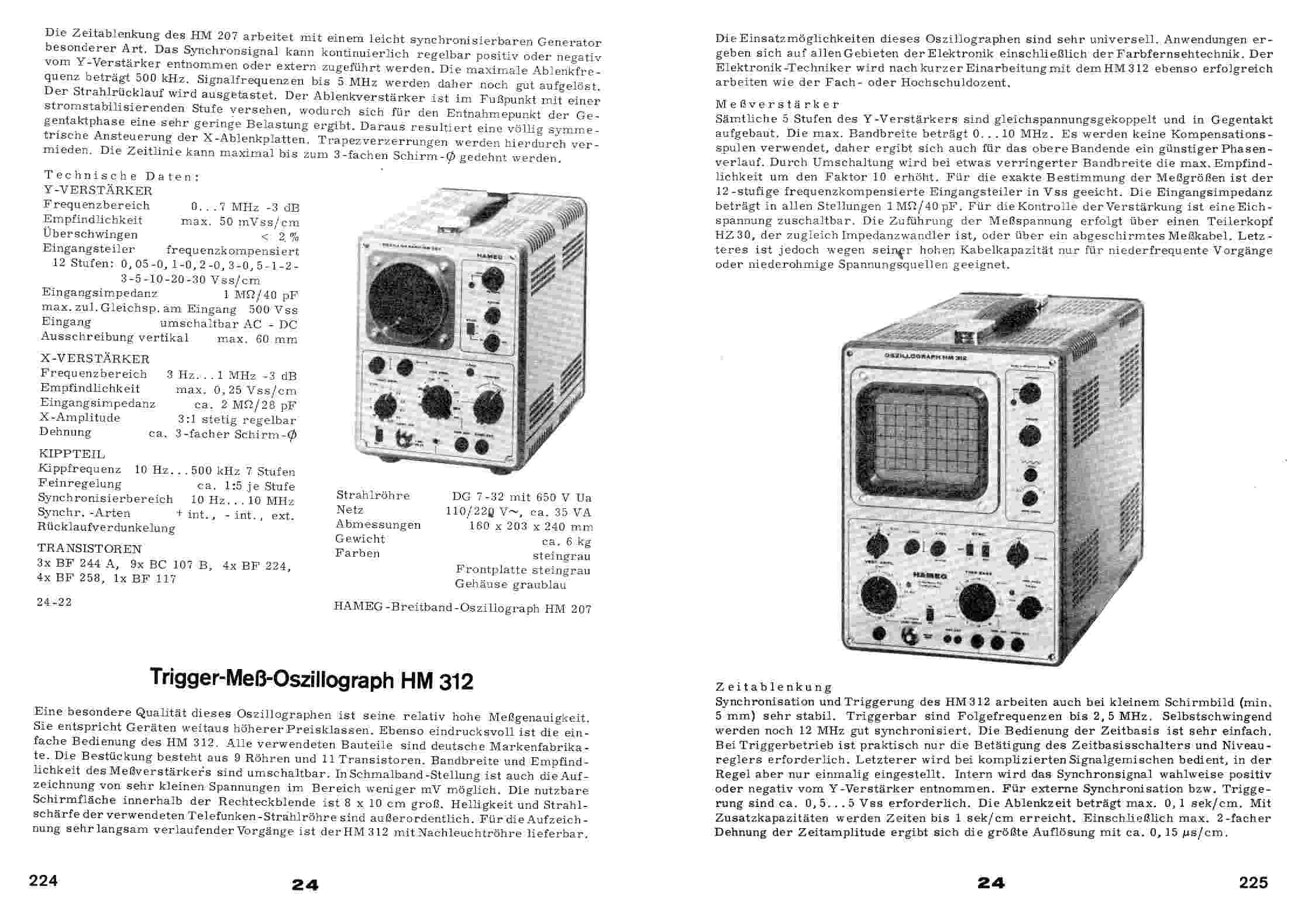
Trigger-Meß-Oszillograph HM312
Zeitableitung
Strahlröhre
Netz
Gewicht
Abmessung
Synchronisierung und Triggerung des HM312 arbeiten bei kleinem Schirmbild, mindestens 5 mm, sehr stabil. Triggerbar sind Folgefrequenzen bis 2,5 MHz.
Motorgehäuse: Beachten Sie die Schraubenlänge. vorgebohrten Gewindelöcher für M6-Gewindeschrauben. Max. Anzugsmoment 7,5 Nm Wir empfehlen,alle vorgebohrten Gewindelöcher für M6-Gewindeschrauben zur Befestigung amTischrah- men zu verwenden. Die Werte der Biegemomente der Hubsäulen gelten nur, wenn der
Byrearrangingthisformula,aminimumvalueforMcanbe V IN(LOW) found: V = D1 and D2 forward voltage V IN(MAX) F M (MIN)= V IN(LOW)= minimuminput voltage V M V IN(MAX) − VSNUB For the circuit shown, with V = 0.6V, V = 20V: F IN(LOW) VM= maximumLT1070 switch voltage VIN(MAX)= maximuminput voltage ( . + 5)( +
Z.B. Max schrieb im Beitrag #7479414: > Danke werde ich ausprobieren. Der Link ist nur ein Beispiel für die AM312 Sensoren. Die gibt es ja wie Sand am Meer. Ob es da Unterschiede in den Shops gibt kann ich
Z.B. Max schrieb im Beitrag #7480114: > Es kann doch nicht sein, dass diese Sensoren nicht funktionieren wenn > die Sonne drauf scheint. Z.B. Max schrieb im Beitrag #7483433: > Nach etwa 1-2 Minuten in
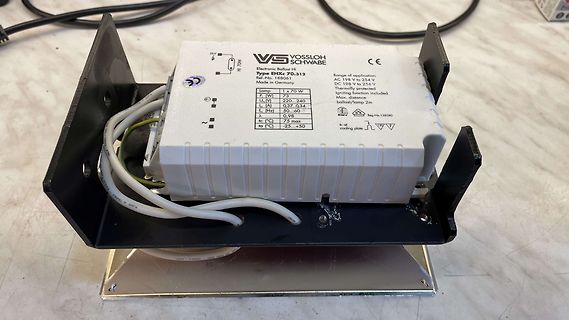
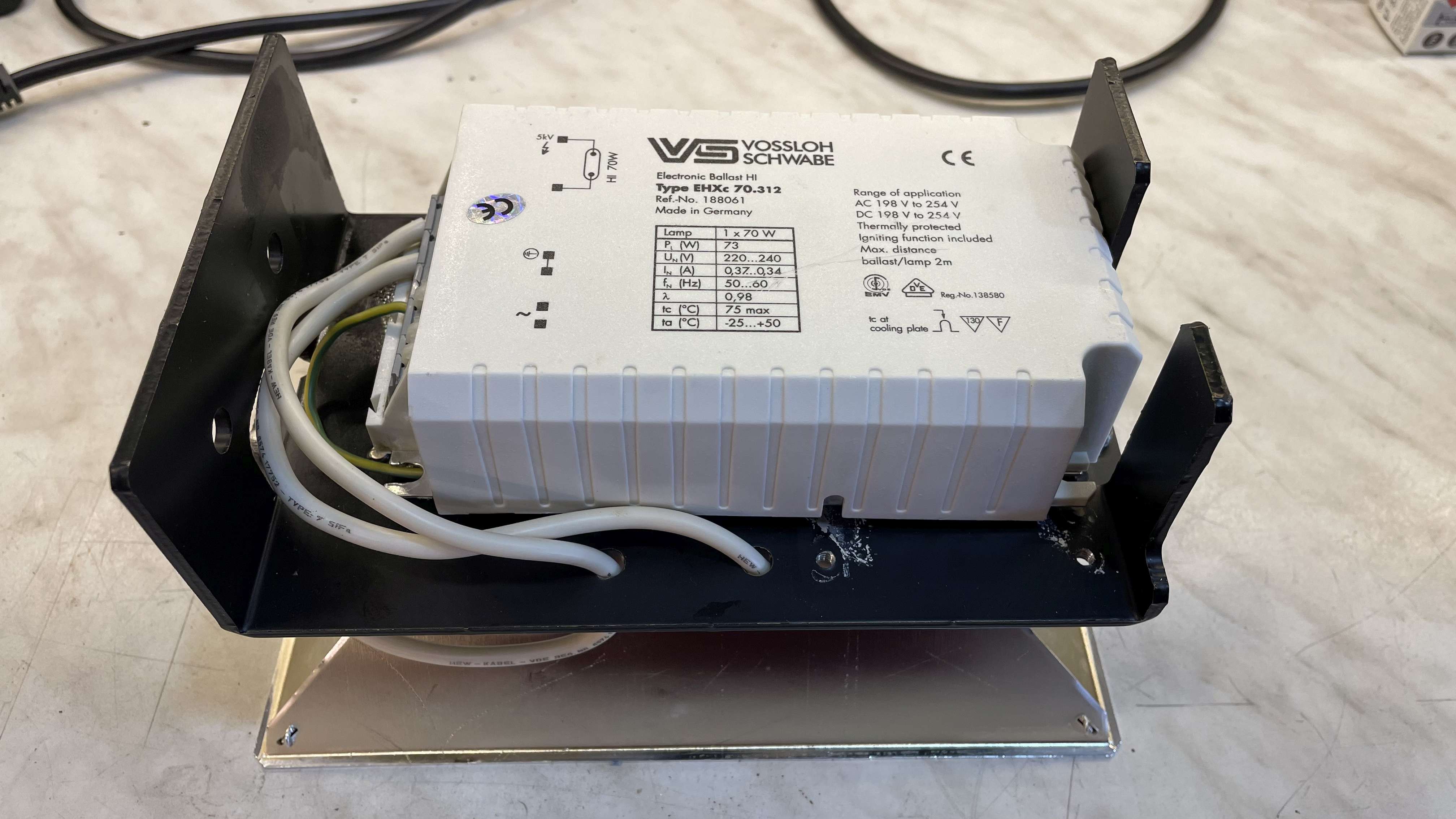
VOSSLOH SCHWABE Electronic Ballast Hi Type EHS 2x312 Ref. No. 188061 Made in Germany Lamp 1 x 70 W U_n [V] 220, 240 I_n [A] 0,31-0,34 f_n [Hz] 50...60 tc [°C] 75 max ta [°C] 25...+50 tc of cooling plate Reg. No. 138580
TSOP312.., TSOP314.. www.vishay.com Vishay Semiconductors IR Receiver Modules for Remote Control Systems FEATURES • Very low supply current • Photo detector and preamplifier in one package • Internal filter
UMICH (J H-H 4) REA RVIEW R 4 1 3 1 E X T E R N A L V I EW R 4131E X T171 1-A ) 0 0 LCL RMT —WRITE 0 - MAX STORE ~VIEW RECALL SAVE —SHIFT INPUT ATTENUATOR - — SWEEP VIDEO I0kHz- .5GHz ( r n i r l R4131A SPECTRUM ANALYZER FREERUN 0 TDE/DIV FLTR +20dBMAX S T A R T H 25VDC MAX P E R /RESET LINE OFF ON PHONE
SPECIFICATIONS 1-1. Electrical specifications 120 V 220 V 230 V 240 V •Power consumption In operation Max. 0.5 A 0.25 A 0.25 A 0.25 A stand-by Max. 0.1 A 0.05 A 0.05 A 0.05 A •Memory protection Back-up battery Vanadium lithium battery Except. USA, CANADA Back-up period 90 days (25 °C) Battery life Replace
name Pin I/O Description DC features Note number USIM_DATA 15 IO USIM card data 1.8V USIM: - bus V max=0.6V IL V IHn=1.2V V OLx=0.45V V min=1.35V OH 3.0V USIM: V max=1.0V IL V IHn=1.95V V OLx=0.45V V min=2.55V OH USIM_CLK 16 DO USIM card clock 1.8V USIM: - line V OLmax=0.45V V min=1.35V OH 3.0V USIM:
Outline Dimensions are shown in millimeters (inches) S M DIMENSIONS 6 B MILLIMETERS INCHES D 5 L MIN MAX MIN MAX A 0.89 1.12 .036 .044 A1 0.01 0.10 .0004 .0039 A2 0.88 1.02 .035 .040 3 6 E b 0.30 0.50 .0119 .0196 E1 c 0.08 0.20 .0032 .0078 ccc C B A D 2.80 3.04 .111 .119 1 2 E 2.10 2.64 .083 .103 E1 1.20
Recommended Soldering Profile ProfileFeature Sn63/Pb37 Pb-Free Average Ramp Rate (T toTL) P 3°C/sec max 3°C/sec max Preheat MinimumTemperature (T SMIN 100°C 150°C MaximumTemperature (T SMAX) 150°C 200°C Time (T SMINtoT SMAX)(S ) 60 sec to 120 sec 60 sec to 180 sec TSMAX toT L Ramp-Up Rate 3°C/sec max
Storage temperature Min. -65⁰C Max. +160⁰C Soldering IEC 68-2-20 Wave – max 260⁰C for max. 10 sec., please refer to usage guidelines Soldering iron – max. 350⁰C for max. 3 sec. Flux tight. Environmental Endurance IEC 68-2-3 Temperature
powerdissipationhasa fixedlimitvalue (P tot max K usuallypresentedformountingbasetemperaturesof25 ˚C. is the maximum d.c. power dissipation below T ). If the mb K At higher temperatures, operating conditions must be transistor is subjected to a mounting-base
minutes' application of rated voltage at 20°C TemperatureCharacteristics Z+105°C / Z+20°C 1.25 (100kHz) (Max.ImpedanceRatio) Z –55°C / Z+20°C 1.25 The specifications listed at right shall be met when the Capacitance change Within ± 20% of the initial capacitance va3)e ( tan δ 150% or less than the initial
without the express written consent of RiTdisplay. http://www.ritdisplay.com 5. MAXIMUM RATINGS ITEM MIN MAX UNIT Condition Remark IC maximum Supply Voltage (V DD -0.3 +3.5 V Ta = 25 °C rating Supply Voltage (Vcc) 8 16 V Ta = 25 °C IC maximum rating Operating Temp. -40 70 °C Storage Temp -40 85 °C Humidity

 Bild
Bild

 Bild
Bild