. Quantum efficiency is symbolized bη and is generally expressed as a percent. Incident photons transfer energy to electrons in the valence band of a photocathode, however not all of these electrons are emitted as photoelectrons. This photoemission takes place according to a certain probability process
current control part, effectively ensuring the pixel point light color height consistent. The data transfer protocol use single NZR communication mode. After the pixel power-on reset, the DIN port receive data from controller, the first pixel collect initial 24bit data then sent to the internal data latch
times. HARDWARE The display is designed to work at an operating voltage range of +3.3V..+5V. Data transfer is either serial and asynchronous in RS-232 format or synchronous via the SPI or I²C specification. To improve data security, a simple protocol is used for all types of transfer. ANALOGUE TOUCHPANEL
Port An asynchronous serial connection to the board controller is provided for application data transfer between a host PC and the target EFM8UB2, which eliminates the need for an external serial port adapter. Isolation Switch VCOM_TX P0.4 (UART0_TX) USB VCOM_RX Board Host P0.5 (UART0_RX) Controller
Howard Johnson, HF-Guru (Ab 01:15:00 kommt die Stelle zum Thema 90° Leiterbahnen) High speed data transfer, Howard Johnson über 90 Grad Ecken in Digitalschaltungen (engl.) Messung von verschiedenen Winkeln von Leiterbahnen mit 17ps TDR, keinerlei Unterschiede! Impedanzen einfach und praktisch messen Impulse
2.4 Serial Input (SI) The descriptions of the pins are listed in Table 2-1. The SI pin is used to transfer data into the device. It receives instructions, addresses and data. Data is latched on the rising edge of the serial clock. TABLE 2-1: PIN FUNCTION TABLE Name PDIP SOIC TSSOP Description 2.5 Serial
Figure 11 for test circuit. Commutating dv/dt is a function of the load−driving thyristor(s) only. TRANSFER CHARACTERISTICS Symbol DC Characteristics Test Conditions Device Min. Typ. Max. Unit IFT LED Trigger Current (Rated FT) Main Terminal MOC3081M 15 mA Voltage = 3 V3) MOC3082M 10 MOC3083M 5 VTM Peak
falling edge of SCLK. The W5500 supports SPI Mode 0 and Mode 3. Both MOSI and MISO signals use transfer sequence from Most Significant Bit (MSB) to Least Significant Bit (LSB) when MOSI signal transmits and MISO signal receives. MOSI & MISO signals always transmit or receive in sequence from the Most
Riser 4 Karten mit wenigen Lanes angeschlossen hat, ist das auf jeden Fall langsamer, weil der Transfer eben schnarch langsam ist. > Mit 16 oder gar 32GB VRAM bleibt das alles nur eine nette Spielerei. Ich finde, auch mit 16GB VRAM kann man schon produktive Sachen machen. Agentic coding ist
.........................................................17 Figure 6-10: Definition of the data transfer condition...................................................................................................17 Figure 6-11: Oscillator Circuit and Display Time Generator...........................
Bausteine. Silabs CP2110-F01-GM QFN24, 4 x 4 mm, Siehe Bild Single-Chip HID USB to UART Data Transfer also seriell RX/TX wird als Windows HID erkannt. ALso z.B direkt in eine Textdatei eingeben. https://www.mouser.de/ProductDetail/Silicon-Labs/CP2110-F01-GM?qs=j12q4iUN960yL%2FAK09Hgyg%3D%3D
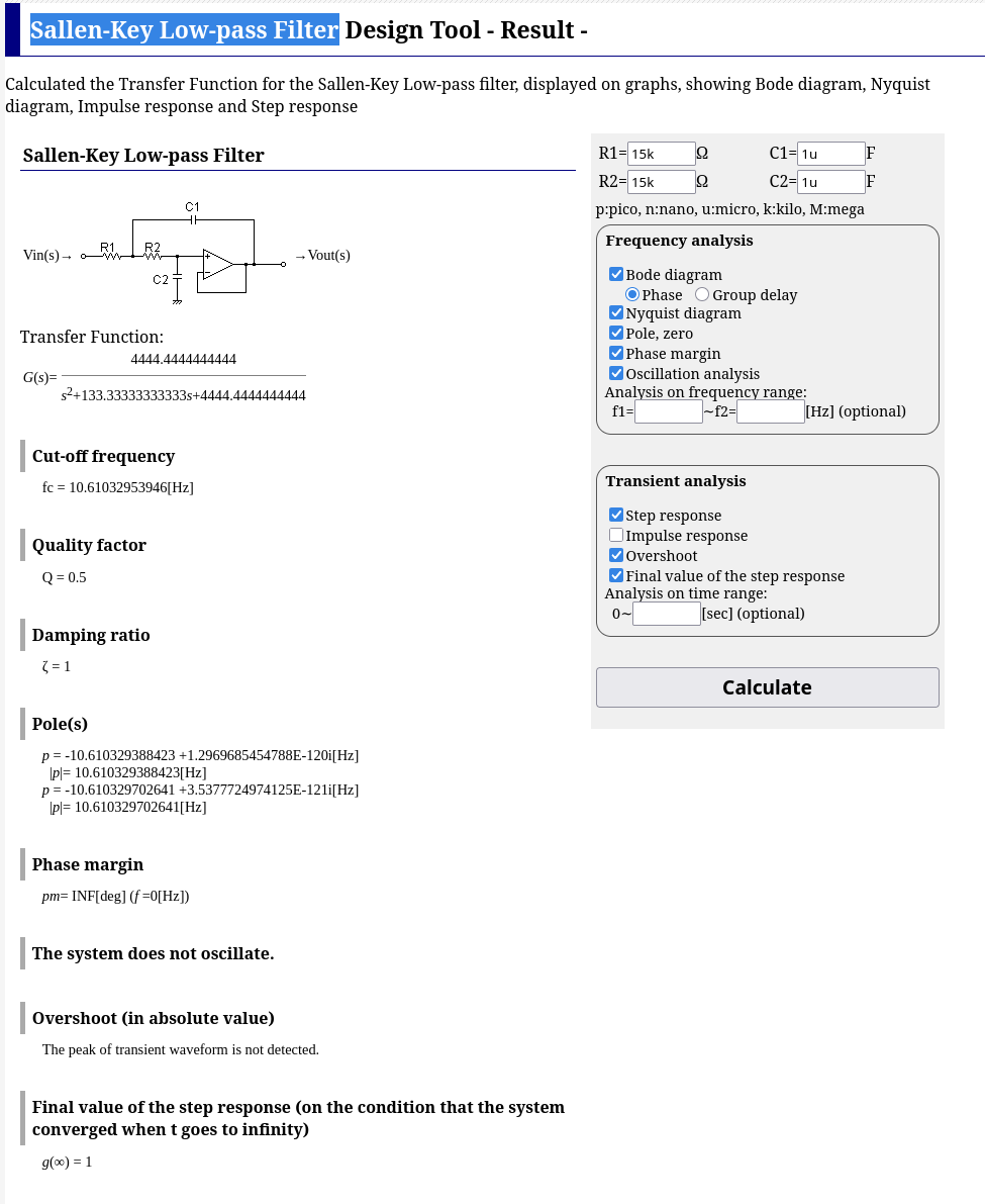
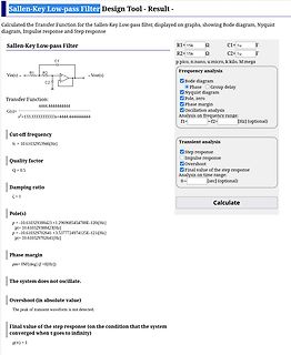
Sallen-Key Low-pass Filter Design Tool - Result -
Calculated the Transfer Function for the Sallen-Key Low-pass filter, displayed on graphs, showing Bode diagram, Nyquist diagram, Impulse response and Step response
Sallen-Key Low-pass Filter
R1=15k Ω
C1=1u F
R2=15k Ω
C2=1u F
p:pico, n:nano, u:micro, k:kilo, M:mega
Transfer Function:
G(s)= 4444.4444444444 s^2+133.3333333333s+4444.4444444444
Cut-off frequency fc = 10.61032953946 [Hz]
Quality factor Q = 0.5
Damping ratio ζ = 1
Pole(s) p = -10.610329388423 + 1.2969685454788E
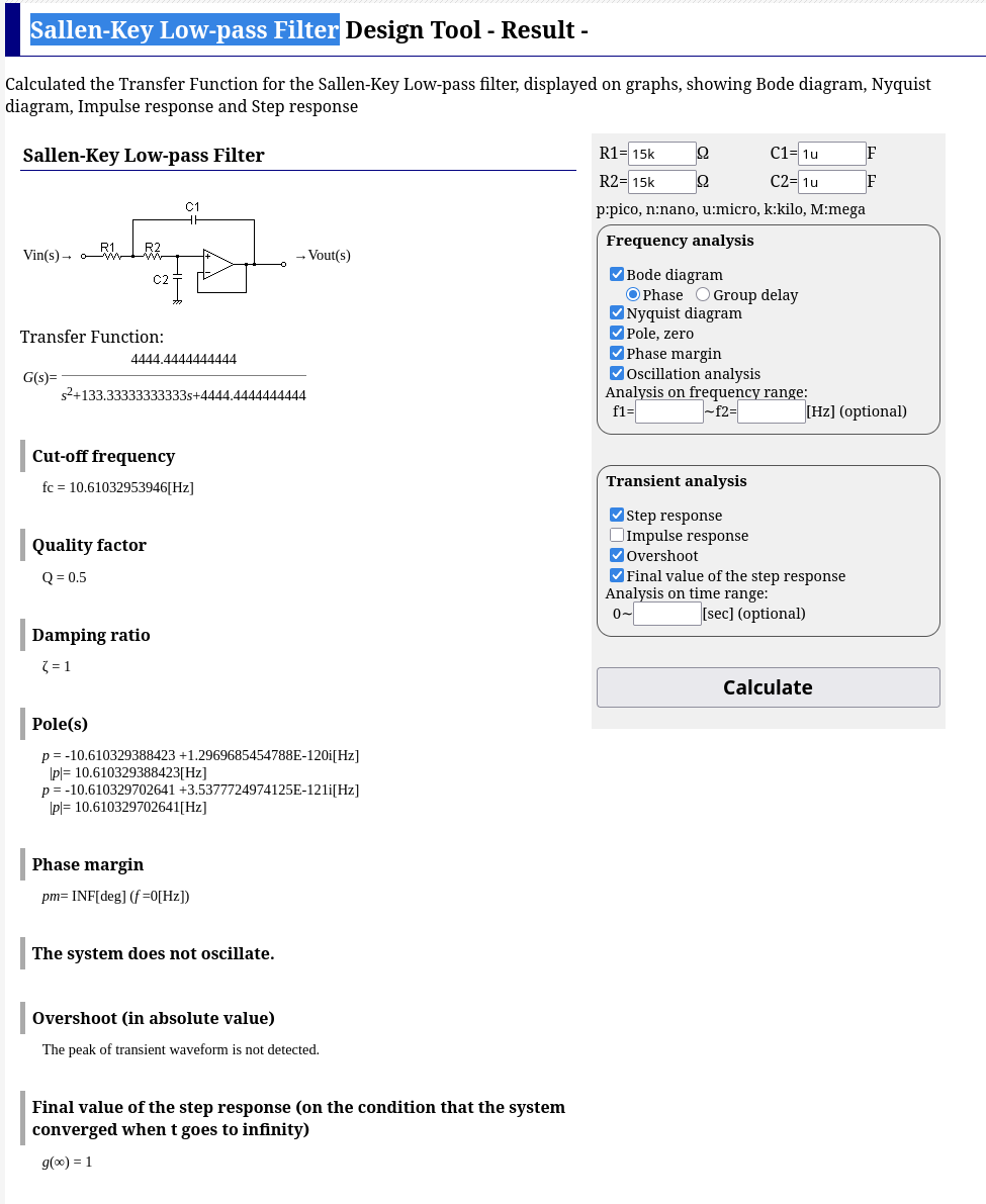
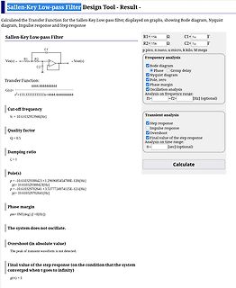
Sallen-Key Low-pass Filter Design Tool - Result -
Calculated the Transfer Function for the Sallen-Key Low-pass filter, displayed on graphs, showing Bode diagram, Nyquist diagram, Impulse response and Step response
Sallen-Key Low-pass Filter
R1=15k Ω
C1=1u F
R2=15k Ω
C2=1u F
p:pico, n:nano, u:micro, k:kilo, M:mega
Transfer Function:
G(s)= 4444.4444444444 s^2+133.3333333333s+4444.4444444444
Cut-off frequency
fc = 10.61032953946 [Hz]
Quality factor
Q = 0.5
Damping ratio
ζ = 1
Pole(s)
p = -10.610329388423 + 1.2969685454788E
.........................................................17 Figure 6-10: Definition of the data transfer condition...................................................................................................17 Figure 6-11: Oscillator Circuit and Display Time Generator...........................
operatingjunctiontemperaturemayimpair device reliability. Charge Pump Frequency Programming The charge transfer frequency can be adjusted between Positive Low Dropout Linear Regulator (LDO +) + 50kHz and 500kHz using an external resistor on the RT Thepositivelowdropoutregulator(LDO )supportsaload pin. At slowerfrequenciestheeffectiveopen-loopoutput
block - Intake-air temperature - Engine speed, petrol engines - Engine speed, diesel engines - Transfer of measured values to the control unit via the serial interface When the system starts up, the remote control performs a self-test. During this process, the function of the internal subassemblies
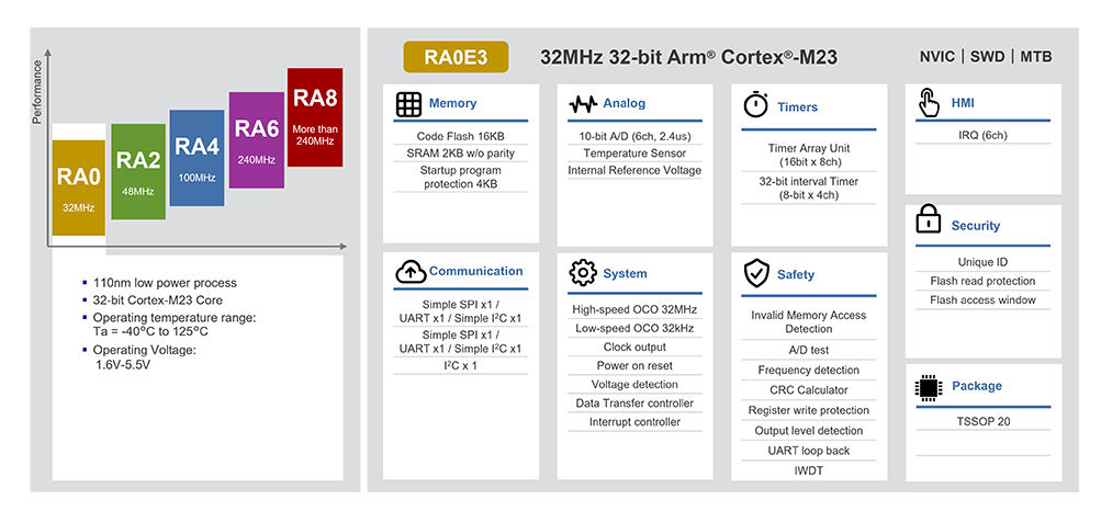
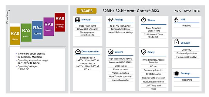
System High-speed OCO 32MHz Low-speed OCO 32kHz Clock output Power on reset Voltage detection Data Transfer controller Interrupt controller HMI IRQ (6ch) Security Unique ID Flash read protection Flash access window Safety Invalid Memory Access Detection A/D test Frequency detection CRC Calculator Register
Tape Phase-Modulated Readback Systems Common-Mode Noise Rejection FILTER NETWORKS FILTER V0 (s) TRANSFER Z NETWORK TYPE V (s) FUNCTION 1 R L 1.4 ▯ 104 ▯ 1 ▯ LOW PASS L s ▯ R▯L R C 1.4 ▯ 10 s HIGH PASS R ▯s ▯ 1▯RC▯ R L C 1.4 ▯ 10 ▯ s ▯ BAND PASS L s ▯ R▯Ls ▯ 1▯LC L R 1.4 ▯ 104 s ▯ 1▯LC BAND REJECT R ▯
die Partnerschaft - nach folgendem Schema - zu beenden: [c] Upon completion of the technology transfer, ROHM and TSMC will amicably conclude their automotive GaN partnership. At the same time, the two companies will continue to strengthen collaboration for higher efficiency and more compact power supply
keep their old setting. In case a byte is not completely transferred, it will be discarded. Data transfer to and from the QN8027 can begin when a start condition is created. This is the case if a transition from HIGH to LOW on the SDA line occurs while the SCL is HIGH. The first byte transferred represents
auf dieser Seite hier sogar schneller zu sein -- vielleicht liegt das daran, daß er den "chunked"-Transfer von mikrocontroller.net oder Cloudflare auflöst, aber das habe ich noch nicht genauer angeschaut. > Wie gehst du mit ungültigen TLS Zertifikaten um? Wird das einfach > abgelehnt oder ignoriert
bit to one will reduce the divisor of the baud rate divider from 16 to 8 effectively doubling the transfer rate for asynchronous communication. • Bit 0 – MPCMn: Multi-processor Communication Mode This bit enables the Multi-processor Communication mode. When the MPCMn bit is written to one, all the incoming
overview TheInfineonCY7C65642 USB2.0 Hubsare low-powerhubsolutionsforUSB which provide maximum transfer efficiencywith no TT multiplexing between downstreamports. The CY7C65642 USB 2.0Hubs integrate1.5 k upstreampull-up resistors for fullspeed operation andall downstream15 kpull-down resistors andseries
Schritten: Zunächst muß der Ziel- oder Quellenkanal spezifiziert werden, danach erfolgt der eigentliche Transfer durch einen Übertragungsbefehl. Der einmal gewählte Kanal bleibt bis zur nächsten Änderung eingestellt. Zielkanal einstellen. a = "0n" Centronics (def) "l" ECB-Bus "2" V24-Schnittstelle "3" Video-RAM
current control part, effectively ensuring the pixel point light color height consistent. The data transfer protocol use single NZR communication mode. After the pixel power-on reset, the DIN port receive data from controller, the first pixel collect initial 24bit data then sent to the internal data latch
ausschließen, also daß der Fehler auch in meinem Code lag. Mein Code hat halt, in der Zeit nach dem USB-Transfer, die PS2++ Maus gepollt und die dort gewonnenen daten an die Standard Digispark Mausklasse übergeben. Das Pollen war auch vor dem nächsten USB-Transfer beendet. Wenn das Windows aber "beschäftigt
verdaut... Fuer synthesefaehigen/portablen Code wuerde ich somit nur die numeric_std-Typen im Transfer empfehlen und die Bound-Checks in allenfalls verketteter Arithmetik nicht der VHDL-Engine ueberlassen, zumal die `integer` je nach Architektur schon mal bei 32 bit begrenzt sind. Verilog ist zwar
schnell genug, am Ende eines DMA-Transfers neue Daten in den Puffer zu schreiben und einen neuen DMA-Transfer zu starten. Das führte zu Störgeräuschen durch die kurze Pause und man musste den DMA-Transfer so konfigurieren, daß er automatisch wiederholt wird und dann immer eine Hälfte des Puffers updaten während
VGS0 V, V =DS V, f=1 MHz Output capacitance Coss - 750 1000 pF VGS0 V, V =DS V, f=1 MHz Reverse transfer capacitance Crss - 27 - pF VGS0 V, V =DS V, f=1 MHz VDD50 V, V =GS V, I =3D A, Turn-on delay time d(on) - 15 - ns RG=1.6 VDD50 V, V =GS V, I =3D A, Rise time r - 9 - ns RG=1.6 VDD50 V, V =GS V, I
good transformer core utilization, leading to increased power density and efficiency. Energy transfer occurs in both switching cycles, unlike flyback converters, resulting in lower current ripple on both primary and secondary sides. Und dem wuerde ich auch zustimmen. Flyback ist zwar okay fuer
Bausteine. Silabs CP2110-F01-GM QFN24, 4 x 4 mm, Siehe Bild Single-Chip HID USB to UART Data Transfer also seriell RX/TX wird als Windows HID erkannt. ALso z.B direkt in eine Textdatei eingeben. https://www.mouser.de/ProductDetail/Silicon-Labs/CP2110-F01-GM?qs=j12q4iUN960yL%2FAK09Hgyg%3D%3D
Trainingsdaten vorgelegen haben – während eine tatsächlich intelligente Entität die Fragen durch Transfer von Wissen aus einem anderen Bereich oder logische Kombination möglicherweise richtig beantworten könnte. Hatte eigentlich gehofft, dass das Video diesen Sachverhalt verständlich und nachvollziehbar
Trainingsdaten vorgelegen haben – während eine tatsächlich intelligente > Entität die Fragen durch Transfer von Wissen aus einem anderen Bereich > oder logische Kombination möglicherweise richtig beantworten könnte. Warum sollte es das nicht können? Es hat doch Bedeutungen. Außerdem finden die LLMs
zu 65 MeV·cm²/mg und einer Immunität gegen Single Event Upset (SEU) validiert für Linear Energy Transfer (LET)-Werte über 60 MeV·cm²/mg. NG-ULTRA integriert ein vollständiges SoC basierend auf einem Quad-Core Arm® Cortex® R52 und bietet hohe Rechenleistung (537k LUTs + 32 Mb RAM), um die komplexesten
Wissenschaft, Wirtschaft, Behörden und internationalen Partnern, um Forschung, Entwicklung und Transfer wirksam zu verbinden. [/c] Für Leser von ucnet ist dies in zweierlei Hinsicht interessant: Nicht nur kann man das eine oder andere Regierungsprojekt abgreifen; die Ansätze können auch in „eigenen
NXP Semiconductors MFRC522 Standard performance MIFARE and NTAG frontend 8.1.3.2 Selectable UART transfer speeds The internal UART interface is compatible with an RS232 serial interface. The default transfer speed is 9.6 kBd. To change the transfer speed, the host controller must write a value for the
: Transfer speed (send) was 81.63 KByte/s Socket_SendTo_Udp: Testing Send with data length 64 Socket_SendTo_Udp: Transfer speed (send) was 160.00 KByte/s Socket_SendTo_Udp: Testing Send with data length 128
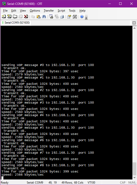
Serial-COM9 (921600) - CRT
File Edit View Options Transfer Script Tools Help
sending UDP message #0 to 192.168.1.30 port 100
Transmit ok.
Time for UDP packet 1024 bytes: 397 usec
speed: 2579 kbytes/sec
sending UDP message #1 to 192.168.1.30 port 100
Transmit
Ethernet Controller W5500 (nicht W5100) - F103 Core Takt 72 MHz - SPI Takt 36 MHz zum W5500, DMA Transfer - Block-Grösse 1024 Bytes - UDP Transfer an PC ohne Handshake Ergibt für den einzelnen Transfer also etwa 2.5 MByte/sec für ein einzelnes UDP Paket.
dem Interrupt selber heraus, das Datenpaket auf eine MPSC queue geschoben und sofort der nächste Transfer gestartet. Interrupts sind eine Art Thread.
scope and PC together with BenchLink software. BenchLink, which runs under Windows, allows easy transfer of scope traces and waveform data to your PC for incorporation into documents or storage. Accessories supplied • Two 1.5 meter, 10:1 Probes (HP 10071A) Power cord for country of destination • • This
: expandtab: #┌────────────────────────────────────────────────────────────────────────────┒ #│ Transfer rate ESP-PSRAM64H (QPI Read Operations) ┃ #┕━━━━━━━━━━━━━━━━━━━━━━━━━━━━━━━━━━━━━━━━━━━━━━━━━━━━━━━━━━━━━━━━━━━━━━━━━━━━┛ from matplotlib import pyplot as plt CLOCK = 84 # in MHz MAX = 256 # in bytes

 Bild
Bild
 Bild
Bild
 Bild
Bild
 Bild
Bild