
-
PDF
OVC3860_RevE_PSKeys_Setting_v1.2.pdf
app_status:This parameter indicates the application status.(1~12) led_on_time: This parameter x 10ms indicates the led on time in 1 cycle . led_off_time: This parameter x 10ms indicates the led off time in 1 cycle. led_repeat_time: This parameter x 50ms indicates the led off time in 1 cycle. led_flash_num
in „OVC3860 RevV Develop Tool - not connected :/“ · HF, Funk und Felder ·
-
PDF
vn820-e.pdf
/W thj-case junction-case Thermalresistance R thj-leadjunction-lead - - - - °C/W Thermalresistance 51.9 (1) 61.9(2) 51.9(2) 76.9(2) °C/W R thj-amb junction-ambient 37 (2) - 37(4) 45(4) °C/W 1. When mounted on a standard single-sided FR-4 board with 0.5cm of Cu (at least 35µm thick). 2 2. When mounted
in „P2PAK in Eagle“ · Platinen ·
-
PDF
es51966.pdf
C0 C1 Conversion period 0 1 70ms 0 0 140ms 1 0 280ms 1 1 700ms When PEAK or PHCAL function is ON, the conversion period becomes: C0 C1 Conversion period 0 1 55ms 0 0 110ms 1 0 220ms 1 1 550ms In frequency and duty cycle (F[0:2] = “110
in „Multimeter UT71A - defekte Kapazitätsmessung“ · Analoge Elektronik und Schaltungstechnik ·
-
PDF
ci11.pdf
per box 2000 pieces per carton (2 boxes) Box dimensions: 35.5 x 24.9 x 15.5 cm Carton dimensions: 51.2 x 36.7 x 17 cm PE BAG PVC TRAY CARTON BOX TEST CIRCUIT DIAGRAM R/C FILTER TEST CIRCUIT Measurements shall be made under the following conditions. The R/C filter circuit as shown is recommended in the
in „Referenzspannung selbst erzeugen“ · Analoge Elektronik und Schaltungstechnik ·
-
Datei
main.c
include <avr/io.h> #include <avr/interrupt.h> /* for sei() */ #include <util/delay.h> /* for _delay_ms() */ #define DDRregister DDRB #define PORTled PORTB #define Arraysize 255 volatile uint8_t a; uint8_t *pointera; uint8_t *pointerb; uint8_t *pointerc; //zaehlt diedruecke nach ISR(TIM0_COMPA_vect){ sei
in „Probleme 3 PWM mit attiny13“ · Mikrocontroller und Digitale Elektronik ·
-
PDF
8810-TuofengSemiconductor_002.pdf
6.2 ns tr Turn-On Rise Time VGS =5V, VDS10V, R =L.35Ω, 12.7 ns tD(off) Turn-Off DelayTime R GEN=3Ω 51.7 ns t Turn-Off Fall Time 16 ns f trr Body Diode Reverse Recovery Time IF7A, dI/dt=100A/µs 17.7 ns Q rr Body Diode Reverse Recovery Charge IF7A, dI/dt=100A/µs 6.7 nC 2 A: The value oθJAs measured with
in „LiPo Tiefentladeschutz 1S/Einzel-Zellen "Mini/Nano"“ · Platinen ·
-
PDF
www.eio.com-hd44780_18-48-46.pdf
clocks COM1 1 2 3 4 8 1 2 V CC V1 V2 (V3) V4 V5 1 frame 1 frame = 3.7 µs × 400 × 8 = 11850 µs = 11.9 ms 1 Frame frequency = = 84.3 Hz 11.9 ms 1/11 duty cycle 400 clocks COM1 1 2 3 4 11 1 2 V CC V1 V2 (V3) V4 V5 1 frame 1 frame = 3.7 µs × 400 × 11 = 16300 µs = 16.3 ms Frame frequency = 1 = 61.4 Hz 16.3 ms 1/16 duty cycle 200 clocks COM1 1 2 3 4 16 1 2 V CC V1 V2 V3 V4 V5 1 frame 1 frame = 3.7 µs × 200 × 16 = 11850 µs = 11.9 ms 1 Frame frequency =11.9 ms = 84.3 Hz Figure 24 Frame Frequency 205 HD44780U
in „Fehler bei 4Bit LCD Init?“ · Mikrocontroller und Digitale Elektronik ·
-
PDF
HD44780__Dot_Matrix_LCD_Controller_Driver_.pdf
clocks COM1 1 2 3 4 8 1 2 V CC V1 V2 (V3) V4 V5 1 frame 1 frame = 3.7 µs × 400 × 8 = 11850 µs = 11.9 ms 1 Frame frequency = = 84.3 Hz 11.9 ms 1/11 duty cycle 400 clocks COM1 1 2 3 4 11 1 2 V CC V1 V2 (V3) V4 V5 1 frame 1 frame = 3.7 µs × 400 × 11 = 16300 µs = 16.3 ms Frame frequency = 1 = 61.4 Hz 16.3 ms 1/16 duty cycle 200 clocks COM1 1 2 3 4 16 1 2 V CC V1 V2 V3 V4 V5 1 frame 1 frame = 3.7 µs × 200 × 16 = 11850 µs = 11.9 ms 1 Frame frequency =11.9 ms = 84.3 Hz Figure 24 Frame Frequency 205 HD44780U
in „Falsche Zeichen bei LCD-Ausgabe“ · Mikrocontroller und Digitale Elektronik ·
-
PDF
HD44780.PDF
clocks COM1 1 2 3 4 8 1 2 V CC V1 V2 (V3) V4 V5 1 frame 1 frame = 3.7 µs × 400 × 8 = 11850 µs = 11.9 ms 1 Frame frequency = = 84.3 Hz 11.9 ms 1/11 duty cycle 400 clocks COM1 1 2 3 4 11 1 2 V CC V1 V2 (V3) V4 V5 1 frame 1 frame = 3.7 µs × 400 × 11 = 16300 µs = 16.3 ms Frame frequency = 1 = 61.4 Hz 16.3 ms 1/16 duty cycle 200 clocks COM1 1 2 3 4 16 1 2 V CC V1 V2 V3 V4 V5 1 frame 1 frame = 3.7 µs × 200 × 16 = 11850 µs = 11.9 ms 1 Frame frequency =11.9 ms = 84.3 Hz Figure 24 Frame Frequency 205 HD44780U
in „Busy-Flag bei LCDs“ · Mikrocontroller und Digitale Elektronik ·
-
PDF
hd44780.pdf
clocks COM1 1 2 3 4 8 1 2 V CC V1 V2 (V3) V4 V5 1 frame 1 frame = 3.7 µs × 400 × 8 = 11850 µs = 11.9 ms 1 Frame frequency = = 84.3 Hz 11.9 ms 1/11 duty cycle 400 clocks COM1 1 2 3 4 11 1 2 V CC V1 V2 (V3) V4 V5 1 frame 1 frame = 3.7 µs × 400 × 11 = 16300 µs = 16.3 ms Frame frequency = 1 = 61.4 Hz 16.3 ms 1/16 duty cycle 200 clocks COM1 1 2 3 4 16 1 2 V CC V1 V2 V3 V4 V5 1 frame 1 frame = 3.7 µs × 200 × 16 = 11850 µs = 11.9 ms 1 Frame frequency =11.9 ms = 84.3 Hz Figure 24 Frame Frequency 205 HD44780U
in „LCD ohne Umlaute?“ · Mikrocontroller und Digitale Elektronik ·
-
PDF
HD44780U.pdf
clocks COM1 1 2 3 4 8 1 2 V CC V1 V2 (V3) V4 V5 1 frame 1 frame = 3.7 µs × 400 × 8 = 11850 µs = 11.9 ms 1 Frame frequency = = 84.3 Hz 11.9 ms 1/11 duty cycle 400 clocks COM1 1 2 3 4 11 1 2 V CC V1 V2 (V3) V4 V5 1 frame 1 frame = 3.7 µs × 400 × 11 = 16300 µs = 16.3 ms Frame frequency = 1 = 61.4 Hz 16.3 ms 1/16 duty cycle 200 clocks COM1 1 2 3 4 16 1 2 V CC V1 V2 V3 V4 V5 1 frame 1 frame = 3.7 µs × 200 × 16 = 11850 µs = 11.9 ms 1 Frame frequency =11.9 ms = 84.3 Hz Figure 24 Frame Frequency 205 HD44780U
in „LCD ohne Datenblatt oder Hinweise zur Pinbelegung“ · Mikrocontroller und Digitale Elektronik ·
-
PDF
hd44780.pdf
clocks COM1 1 2 3 4 8 1 2 V CC V1 V2 (V3) V4 V5 1 frame 1 frame = 3.7 µs × 400 × 8 = 11850 µs = 11.9 ms 1 Frame frequency = = 84.3 Hz 11.9 ms 1/11 duty cycle 400 clocks COM1 1 2 3 4 11 1 2 V CC V1 V2 (V3) V4 V5 1 frame 1 frame = 3.7 µs × 400 × 11 = 16300 µs = 16.3 ms Frame frequency = 1 = 61.4 Hz 16.3 ms 1/16 duty cycle 200 clocks COM1 1 2 3 4 16 1 2 V CC V1 V2 V3 V4 V5 1 frame 1 frame = 3.7 µs × 200 × 16 = 11850 µs = 11.9 ms 1 Frame frequency =11.9 ms = 84.3 Hz Figure 24 Frame Frequency 205 HD44780U
in „LCD (von Tel) -Problem“ · Mikrocontroller und Digitale Elektronik ·
-
PDF
hd44780.pdf
clocks COM1 1 2 3 4 8 1 2 V CC V1 V2 (V3) V4 V5 1 frame 1 frame = 3.7 µs × 400 × 8 = 11850 µs = 11.9 ms Frame frequency = 1 = 84.3 Hz 11.9 ms 1/11 duty cycle 400 clocks COM1 1 2 3 4 11 1 2 V CC V1 V2 (V3) V4 V5 1 frame 1 frame = 3.7 µs × 400 × 11 = 16300 µs = 16.3 ms 1 Frame frequency = = 61.4 Hz 16.3 ms 1/16 duty cycle 200 clocks COM1 1 2 3 4 1 2 V 16 CC V1 V2 V3 V4 V5 1 frame 1 frame = 3.7 µs × 200 × 16 = 11850 µs = 11.9 ms Frame frequency = 1 = 84.3 Hz 11.9 ms Figure 24 Frame Frequency 205 HD44780U
in „HD44780 Zeichen im ROM“ · Mikrocontroller und Digitale Elektronik ·
-
PDF
hd44780.pdf
clocks COM1 1 2 3 4 8 1 2 V CC V1 V2 (V3) V4 V5 1 frame 1 frame = 3.7 µs × 400 × 8 = 11850 µs = 11.9 ms 1 Frame frequency = = 84.3 Hz 11.9 ms 1/11 duty cycle 400 clocks COM1 1 2 3 4 11 1 2 V CC V1 V2 (V3) V4 V5 1 frame 1 frame = 3.7 µs × 400 × 11 = 16300 µs = 16.3 ms Frame frequency = 1 = 61.4 Hz 16.3 ms 1/16 duty cycle 200 clocks COM1 1 2 3 4 16 1 2 V CC V1 V2 V3 V4 V5 1 frame 1 frame = 3.7 µs × 200 × 16 = 11850 µs = 11.9 ms 1 Frame frequency =11.9 ms = 84.3 Hz Figure 24 Frame Frequency 205 HD44780U
in „Sinnlose Probleme mit LCD...“ · Mikrocontroller und Digitale Elektronik ·
-
PDF
hd44780.pdf
clocks COM1 1 2 3 4 8 1 2 V CC V1 V2 (V3) V4 V5 1 frame 1 frame = 3.7 µs × 400 × 8 = 11850 µs = 11.9 ms 1 Frame frequency = = 84.3 Hz 11.9 ms 1/11 duty cycle 400 clocks COM1 1 2 3 4 11 1 2 V CC V1 V2 (V3) V4 V5 1 frame 1 frame = 3.7 µs × 400 × 11 = 16300 µs = 16.3 ms Frame frequency = 1 = 61.4 Hz 16.3 ms 1/16 duty cycle 200 clocks COM1 1 2 3 4 16 1 2 V CC V1 V2 V3 V4 V5 1 frame 1 frame = 3.7 µs × 200 × 16 = 11850 µs = 11.9 ms 1 Frame frequency =11.9 ms = 84.3 Hz Figure 24 Frame Frequency 205 HD44780U
in „System(Mikrocontroller usw) mit Batterie betreiben“ · Mikrocontroller und Digitale Elektronik ·
-
PDF
hd44780.pdf
clocks COM1 1 2 3 4 8 1 2 V CC V1 V2 (V3) V4 V5 1 frame 1 frame = 3.7 µs × 400 × 8 = 11850 µs = 11.9 ms 1 Frame frequency = = 84.3 Hz 11.9 ms 1/11 duty cycle 400 clocks COM1 1 2 3 4 11 1 2 V CC V1 V2 (V3) V4 V5 1 frame 1 frame = 3.7 µs × 400 × 11 = 16300 µs = 16.3 ms Frame frequency = 1 = 61.4 Hz 16.3 ms 1/16 duty cycle 200 clocks COM1 1 2 3 4 16 1 2 V CC V1 V2 V3 V4 V5 1 frame 1 frame = 3.7 µs × 200 × 16 = 11850 µs = 11.9 ms 1 Frame frequency =11.9 ms = 84.3 Hz Figure 24 Frame Frequency 205 HD44780U
in „ATMEL_2x16LCD_Zeile 2“ · Mikrocontroller und Digitale Elektronik ·
-
PDF
HD44780.pdf
clocks COM1 1 2 3 4 8 1 2 V CC V1 V2 (V3) V4 V5 1 frame 1 frame = 3.7 µs × 400 × 8 = 11850 µs = 11.9 ms 1 Frame frequency = = 84.3 Hz 11.9 ms 1/11 duty cycle 400 clocks COM1 1 2 3 4 11 1 2 V CC V1 V2 (V3) V4 V5 1 frame 1 frame = 3.7 µs × 400 × 11 = 16300 µs = 16.3 ms Frame frequency = 1 = 61.4 Hz 16.3 ms 1/16 duty cycle 200 clocks COM1 1 2 3 4 16 1 2 V CC V1 V2 V3 V4 V5 1 frame 1 frame = 3.7 µs × 200 × 16 = 11850 µs = 11.9 ms 1 Frame frequency =11.9 ms = 84.3 Hz Figure 24 Frame Frequency 205 HD44780U
in „LCD Ansteuerung (PIC 18F1220)“ · Mikrocontroller und Digitale Elektronik ·
-
PDF
HD44780.PDF
clocks COM1 1 2 3 4 8 1 2 V CC V1 V2 (V3) V4 V5 1 frame 1 frame = 3.7 µs × 400 × 8 = 11850 µs = 11.9 ms 1 Frame frequency = = 84.3 Hz 11.9 ms 1/11 duty cycle 400 clocks COM1 1 2 3 4 11 1 2 V CC V1 V2 (V3) V4 V5 1 frame 1 frame = 3.7 µs × 400 × 11 = 16300 µs = 16.3 ms Frame frequency = 1 = 61.4 Hz 16.3 ms 1/16 duty cycle 200 clocks COM1 1 2 3 4 16 1 2 V CC V1 V2 V3 V4 V5 1 frame 1 frame = 3.7 µs × 200 × 16 = 11850 µs = 11.9 ms 1 Frame frequency =11.9 ms = 84.3 Hz Figure 24 Frame Frequency 205 HD44780U
in „LCD Display in 4 Bit Modus bringen“ · Mikrocontroller und Digitale Elektronik ·
-
PDF
HD44780.PDF
clocks COM1 1 2 3 4 8 1 2 V CC V1 V2 (V3) V4 V5 1 frame 1 frame = 3.7 µs × 400 × 8 = 11850 µs = 11.9 ms 1 Frame frequency = = 84.3 Hz 11.9 ms 1/11 duty cycle 400 clocks COM1 1 2 3 4 11 1 2 V CC V1 V2 (V3) V4 V5 1 frame 1 frame = 3.7 µs × 400 × 11 = 16300 µs = 16.3 ms Frame frequency = 1 = 61.4 Hz 16.3 ms 1/16 duty cycle 200 clocks COM1 1 2 3 4 16 1 2 V CC V1 V2 V3 V4 V5 1 frame 1 frame = 3.7 µs × 200 × 16 = 11850 µs = 11.9 ms 1 Frame frequency =11.9 ms = 84.3 Hz Figure 24 Frame Frequency 205 HD44780U
in „Datenblatt zu HD44780 1602 LCD Modul Display Anzeigen 2X16 Zeichen“ · Mikrocontroller und Digitale Elektronik ·
-
PDF
HD44780.pdf
clocks COM1 1 2 3 4 8 1 2 V CC V1 V2 (V3) V4 V5 1 frame 1 frame = 3.7 µs × 400 × 8 = 11850 µs = 11.9 ms 1 Frame frequency = = 84.3 Hz 11.9 ms 1/11 duty cycle 400 clocks COM1 1 2 3 4 11 1 2 V CC V1 V2 (V3) V4 V5 1 frame 1 frame = 3.7 µs × 400 × 11 = 16300 µs = 16.3 ms Frame frequency = 1 = 61.4 Hz 16.3 ms 1/16 duty cycle 200 clocks COM1 1 2 3 4 16 1 2 V CC V1 V2 V3 V4 V5 1 frame 1 frame = 3.7 µs × 200 × 16 = 11850 µs = 11.9 ms 1 Frame frequency =11.9 ms = 84.3 Hz Figure 24 Frame Frequency 205 HD44780U
in „Standart LCD per i2c expander betreiben“ · Mikrocontroller und Digitale Elektronik ·
-
PDF
hd44780u_Datenblatt.pdf
clocks COM1 1 2 3 4 8 1 2 V CC V1 V2 (V3) V4 V5 1 frame 1 frame = 3.7 µs × 400 × 8 = 11850 µs = 11.9 ms 1 Frame frequency = = 84.3 Hz 11.9 ms 1/11 duty cycle 400 clocks COM1 1 2 3 4 11 1 2 V CC V1 V2 (V3) V4 V5 1 frame 1 frame = 3.7 µs × 400 × 11 = 16300 µs = 16.3 ms Frame frequency = 1 = 61.4 Hz 16.3 ms 1/16 duty cycle 200 clocks COM1 1 2 3 4 16 1 2 V CC V1 V2 V3 V4 V5 1 frame 1 frame = 3.7 µs × 200 × 16 = 11850 µs = 11.9 ms 1 Frame frequency =11.9 ms = 84.3 Hz Figure 24 Frame Frequency 205 HD44780U
in „hd44780 / LCD SC1602D / ATmega16 (STK500)“ · Mikrocontroller und Digitale Elektronik ·
-
PDF
HD44780U.pdf
clocks COM1 1 2 3 4 8 1 2 V CC V1 V2 (V3) V4 V5 1 frame 1 frame = 3.7 µs × 400 × 8 = 11850 µs = 11.9 ms 1 Frame frequency = = 84.3 Hz 11.9 ms 1/11 duty cycle 400 clocks COM1 1 2 3 4 11 1 2 V CC V1 V2 (V3) V4 V5 1 frame 1 frame = 3.7 µs × 400 × 11 = 16300 µs = 16.3 ms Frame frequency = 1 = 61.4 Hz 16.3 ms 1/16 duty cycle 200 clocks COM1 1 2 3 4 16 1 2 V CC V1 V2 V3 V4 V5 1 frame 1 frame = 3.7 µs × 200 × 16 = 11850 µs = 11.9 ms 1 Frame frequency =11.9 ms = 84.3 Hz Figure 24 Frame Frequency 205 HD44780U
in „LCD Initialisierung Mikrocontroller“ · Mikrocontroller und Digitale Elektronik ·
-
PDF
TMS279X_DataSheet.pdf
compare II & III 1 U = Update SSO U = 0, Update SSO to 0 U = 1, Update SSO to 1 II & III 2 E = 1 5 ms Delay E = 0, No. 15 ms delay E = 1, 15 ms delay (30 ms for 1 MHz) II 3 S = Side Compare Flag S = 0, Compare for side 0 S = 1, Compare for side 1 II 3 L = Sector Length Flag LBS's Sector Length in ID
in „Floppy FDD Diskette an AVR Mikrocontroller ATmega Beispiele Assembler“ · Projekte & Code ·
-
PDF
ucc28084.pdf
SOFT START ON OFF SOIC-8 (D) PDIP-8 (P) TSSOP-8 (PW) 12.5 V 8.3 V UCC28083D UCC28083P UCC28083PW 3.5 ms 4.3 V 4.1 V UCC28084D UCC28084P UCC28084PW –40°C to 85C 12.5 V 8.3 V UCC28085D UCC28085P UCC28085PW 75 µs 4.3 V 4.1 V UCC28086D UCC28086P UCC28086PW 12.5 V 8.3 V UCC38083D UCC38083P UCC38083PW 3.5 ms
in „UCC28084 läuft nicht an“ · Analoge Elektronik und Schaltungstechnik ·
-
PDF
L7200.PDF
SHOCK SENSOR DETECTOR SPINDLE DRIVER ■INTERNAL POR DELAY TIME AT POWER ON ■ 2.5A DRIVE CAPABILITY (80ms) ■ 0.75 TOTAL BRIDGE IMPEDANCE AT ■INTERNAL ISOFET FOR BEMF 125°C RECTIFICATION ■ SMOOTHDRIVE™ ARCHITECTURE ■THERMAL SHUTDOWN AND PRETHERMAL WARNING ■ SINUSOIDAL DRIVING, VOLTAGE MODE ■ BIPOLAR DRIVING
in „Externe Festplatte durch falsches Netzteil zerstört“ · PC Hard- und Software ·
-
PDF
RTL8111B_8168B_Registers_DataSheet_1.0.pdf
...................................................................................................51 5.7.6. Message Data.......................................................................................................................................................51 6. FUNCTIONAL DESCRIPTION.
-
Datei
Parkhaus.c51
#pragma cd pl(9999) #include <reg51.h> #define KEY_INPUT P2 #define KEY_PLUS 0x01 // P2.0 #define KEY_MINUS 0x02 // P2.1 #define LED_OUTPUT P0 char key_state; char key_press; void to_int( void ) interrupt INT_T0 { static char ct0, ct1; char i; TH0 |= -16; // interrupt every 4.096ms at 12MHz i = key_state ^ ~KEY_INPUT; // key changed ? ct0 = ~( ct0 & i ); // reset or count ct0 ct1 = ct0 ^ ct1 & i; // reset or count ct1 i &= ct0 & ct1; // count until roll over key_state ^= i; //
in „Hallo Jungs - brauche Hilfe bei Assemblerprogrammierung!“ · Projekte & Code ·
-
Datei
main_neu.c
PORTD // SDA Port E #define SCL_PORT PORTD // SCL Port E #define US_address 0xE0 #define Start_US 0x51 int main (void) { uint8_t distance_low; uint8_t distance_high; uint16_t distance; DDRB = 0xff; unsigned char busy; unsigned int i; while (1) { // start execution of program i2c_init(); // initialize
in „Problem beim auslesen von Ultraschall“ · Mikrocontroller und Digitale Elektronik ·
-
Datei
timer.h
General Public License along * with this program; if not, write to the Free Software Foundation, Inc., * 51 Franklin Street, Fifth Floor, Boston, MA 02110-1301 USA. * *************************************************************************** * * This version of GPL is at http://www.gnu.org/licenses/old-licenses
in „ein plattformunabhängiger Tetris-Clone“ · Projekte & Code ·
-
 Bild
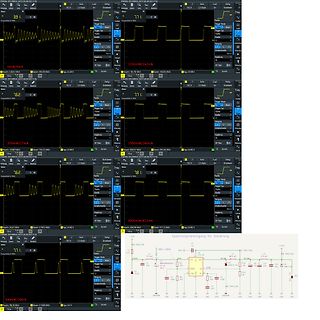
Oszilloskop-Messungen und Schaltplan einer Spannungsversorgung
39.1 V, 2 uF, 2.50 ms, 200mV/27mA, 1500mV/260mA, 78.1 V, 3000mV/412mA, Spannungsversorgung für Steuerung, PWR_FLAG, C1, C2, C3, C4, C5, C6, C7, C8, C9, C10, C11, C12, C13, C14, C15, R1, R2, R3, R4, R5, R6, R7, R8, R9, R10
in „Einschaltdauer PWM bei Step Down Converter“ · Analoge Elektronik und Schaltungstechnik · · Screenshots
-
PDF
app162__Interfacing_DS1820_in_a_MC_environment_.pdf
pullup Figure 3. Write and Read Time Slots START START OF SLOT OF SLOT WRITE “0” SLOT WRITE “1” SLOT 1 ms < REC<¥ 60 ms < X “0” < 120 ms > 1 ms VPU 1-WIRE BUS GND DS18x20/DS1822 Samples DS18x20/DS1822 Samples MIN TYP MAX MIN TYP MAX 15 ms 15 ms 30 ms 15 ms 15 ms 30 ms READ “0” SLOT READ “1” SLOT 1 ms < REC<¥ VPU 1-WIRE BUS GND Master samples > 1 ms Master samples > 1 ms 15 ms 45 ms 15 ms SOFTWARE CONTROL Delay Example In order to accurately control the special timing requirements of the 1-Wire TM interface, certain key // DELAY - with an 11.059MHz
in „DS18B20 zu komplizierte Ansteuerung?“ · Mikrocontroller und Digitale Elektronik ·
-
PDF
app162__Interfacing_DS1820_in_a_MC_environment_.pdf
pullup Figure 3. Write and Read Time Slots START START OF SLOT OF SLOT WRITE “0” SLOT WRITE “1” SLOT 1 ms < REC<¥ 60 ms < X “0” < 120 ms > 1 ms VPU 1-WIRE BUS GND DS18x20/DS1822 Samples DS18x20/DS1822 Samples MIN TYP MAX MIN TYP MAX 15 ms 15 ms 30 ms 15 ms 15 ms 30 ms READ “0” SLOT READ “1” SLOT 1 ms < REC<¥ VPU 1-WIRE BUS GND Master samples > 1 ms Master samples > 1 ms 15 ms 45 ms 15 ms SOFTWARE CONTROL Delay Example In order to accurately control the special timing requirements of the 1-Wire TM interface, certain key // DELAY - with an 11.059MHz
-
PDF
ADXL202E.pdf
A125 kΩresistor will set the duty cycle repetition rate to approxi- 3V TO 5.25V C mately 1 kHz, or 1 ms. The device is designed to operate at duty V X X cycle periods between 0.5 ms and 10 ms. DD FILT SELF-TEST X SENSOR RFILT Table II. Resistor Values to Set T2 32k XOUT C DEMOD ANALOG O T2 R SET C TO U DC OSCILLATOR ADXL202E DUTY N P 1 ms 125 kΩ (ADC) E 2 ms 250 kΩ DEMOD R Y R Y SENSOR 32kLT OUT 5 ms 625 kΩ COM YFILT T2 10 ms 1.25 MΩ C Y RSET Note that the R SETshould always be included, even if only an analog output is desired. Use an
in „Noise Performance“ · Mikrocontroller und Digitale Elektronik ·
-
PDF
DM_D110_Steuerkommandos.pdf
...................................................................................................51 US @........................................................................................................................................51 US : ...................................................
in „VFD "Kundendisplay"-Ansteuerung“ · Mikrocontroller und Digitale Elektronik ·
-
PDF
m1306b.pdf
Note (Ref. WM_ASW_OAT_DVD_00062) 1.1.2 AT Software Documentation [7] AT commands interface Guide for X51 (Ref. WM_ASW_OAT_UGD_00016) [8] Customer Release Note X51 (Ref. WM_ASW_OAT_DVD_00120) 1.1.3 Other Documents [9] Firmware upgrade procedure (Ref. WM_SW_GEN_UGD_001) Note: New versions of software may
in „[V] gebrauchtes GSM-Modem von Wavecom Fastrack“ · Markt ·
-
PDF
DOGM162_DOGM163_4Bit_SPI_3V3_5V0_Initialize.pdf
------------------------------------------------------------------------------------- ; Wait 2.500 ms Start: rcall LCD_line1 ldi R16 , 1 ; 10 ms rcall Wait ldi R16 , 'A' rcall LCD_data ldi R16 , 'f' rcall LCD_data ldi R16 , 't' rcall LCD_data ldi R16 , 'e' rcall LCD_data ldi R16 , 'r' rcall LCD_data
-
PDF
lnk302_304-306-179954-2.pdf
pin. The values of R1 and R3 are selected such high. If the FEEDBACK pin is not pulled high for 50 ms, the that, at the desired output voltage, the voltage at the power MOSFET switching is disabled for 800 ms. The auto- FEEDBACK pin is 1.65 V. restart alternately enables and disables the switching of
in „AC/DC Wandler auf Zeitschaltuhr durchgebrannt“ · Analoge Elektronik und Schaltungstechnik ·
-
PDF
NT-C1641A-BTSESW-A0.pdf
CONDI MIN. TYP. MAX. ITEM L TION UNIT REF. Contrast CR 25℃ -- 12 -- Note1 Rise Time tr 25℃ -- 160 240 ms Note2 Fall Time tf 25℃ -- 100 150 ms note 2 Viewing θ1-θ2 -- -- 60 25℃ DEG Note 3 Angle Ø1, Ø2 -40 -- 40 Frame Ff 25℃ -- -- Hz note 2 70 Frequency Note(1): Contrast ratio is defined under the following
-
Datei
funkuhr.c
Interrupt dcf.z_1 = dcf.z; // Uhrenroutine if (clock_count == 200) // Zähler für Uhr auf 200 ? (1s / 5ms = 200) { clock_count = 1; // ja, Zähler auf eins clock_inc(); // Uhr weiterzählen display_out(); // Und neuen Stand ans Display schicken } else clock_count++; // sonst: weiterzählen } /**************
in „Timing für interne Uhr“ · Mikrocontroller und Digitale Elektronik ·
-
Datei
funkuhr.c
Interrupt dcf.z_1 = dcf.z; // Uhrenroutine if (clock_count == 200) // Zähler für Uhr auf 200 ? (1s / 5ms = 200) { clock_count = 1; // ja, Zähler auf eins clock_inc(); // Uhr weiterzählen display_out(); // Und neuen Stand ans Display schicken } else clock_count++; // sonst: weiterzählen } /**************
in „DCF77, die 100ste..“ · Mikrocontroller und Digitale Elektronik ·
-
Datei
i2clcd.h
microcontroller */ #endif #define wait1us _delay_loop_1((F_CPU * 0.000001) / 3) /**< 1 us delay */ #define wait1ms _delay_loop_2((F_CPU * 0.001) / 4) /**< 1 ms delay */ /*@}*/ //------------------------------------------------------------------------------------------------------------------- #include <util/delay.h
in „4x20-LCD läuft nicht richtig“ · Mikrocontroller und Digitale Elektronik ·
-
Datei
temp_senden.asm
ret; rjmp mainloop waiting: push xl ;Inhalt sichern ldi xl,80 ; ldi xl,20 powerupwait: rcall delay5ms dec xl brne powerupwait pop xl ;alten Inhalt zurück holen ret delay5ms: ;5ms Pause für manche Befehle push zl ;alten Inhalt push zh ;sichern ldi zh,high(clock/11000*50);Verzögerungswert für 50ms ldi zl,low(clock/11000*50) ;setzen delay5ms1: rcall delay5ms2 ;7 Takte vertrödeln sbiw zh:zl,1 ;-1 (2 weitere Takte) brne delay5ms1 ;0? nein, nochmal (2 Takte) pop zh ;alten Inhalt pop zl ;zurück holen delay5ms2: ret ;zurück... ;**************
in „DS1820/DS18S20“ · Mikrocontroller und Digitale Elektronik ·
-
PDF
LTC2418.pdf
tLEO External Oscillator Low Period ● 0.25 390 µs tCONV Conversion Time FO= 0V ● 130.86 133.53 136.20 ms FO = CC ● 157.03 160.23 163.44 ms External Oscillator (Note 11) ● 20510/fEOSC(in kHz) ms fISCK Internal SCK Frequency Internal Oscillator (Note 10) 19.2 kHz External Oscillator (Notes 10, 11) fEOSC8
in „4-kanal PT100 Multiplexer 24bit Schaltung, Messbrücke, ratiometrisch, c't lab“ · Analoge Elektronik und Schaltungstechnik ·
-
Datei
OneWire.c
bits are undefined, so let's zero them if (cfg == 0x00) raw = raw & ~7; // 9 bit resolution, 93.75 ms else if (cfg == 0x20) raw = raw & ~3; // 10 bit res, 187.5 ms else if (cfg == 0x40) raw = raw & ~1; // 11 bit res, 375 ms //// default is 12 bit resolution, 750 ms conversion time } celsius = (float)
in „Böses One-Wire device“ · Mikrocontroller und Digitale Elektronik ·
-
PDF
XGZP6857D-Pressure-Sensor-V2.9.pdf
64/1 100b: 4/1 001b: 32/1 101b: 1/1 0x03.[2:0] PT_R[2:0] 010b: 16/1 Others: 128/1 011b: 8/1 000b: 0ms 100b: 500ms 001b: 62.5ms 101b: 750ms 0x03.[5:3] T_SB[2:0] 010b: 125ms 110b: 1000ms 011b: 250ms 111b: 2000ms 0x03.[7:6] reserved reserve 0x03.[7:6] XGZP6857D_DataSheet_EN_V2.9 www.CFSensor.com 6 1/ Calibrated
in „CFSensors XGZP6857D Drucksensor Informationen“ · Mikrocontroller und Digitale Elektronik ·
-
PDF
DS_BT81X.pdf
.... 48 6.4 AC Characteristics.................................................................... 51 6.4.1 System Clock and Reset............................................................................. 51 6.4.2 SPI Interface Timing................................................................
in „STM32F407 DISCOVERY mit EVE3 50GTPC von MatrixOrbital“ · Mikrocontroller und Digitale Elektronik ·
-
PDF
WBND-S-A0011794841-1.pdf
Sector14 (K B) 5 B c 4 l ( Sectr 1(4KB) B Sectr 0(4KB) Id iidualB lck Locks: 32 Sectors(Top /o tom ) 51 0Blocks Bl ck51 0(64 KB) IdiviualBlockLock: 36h+ Address IdiviualBlockU nlck: 39h+ Address Read Blck Lock: 3Dh +A ddrss Block1 (64K B) GlobalBlck Lock: 7Eh Sector15 (K B) GlobalBlck Unlock: Sector14
-
PDF
ABLIC-S-8520-8251_Series.pdf
kHz typ. (A, B types) 60 kHz typ. (C, D types) 300 kHz typ. (E, F types) Soft-start function: 8 ms. typ. (A, B types) 12 ms. typ. (C, D types) 4.5 ms. typ. (E, F types) With a shutdown function With a built-in overload protection circuit Overload detection time: 4 ms. typ. (A type) 14 ms. typ.
in „EHAYP 7606 - Welcher IC?“ · Analoge Elektronik und Schaltungstechnik ·
-
PDF
Datasheet.hk_mon35w82_8390983.pdf
very low speed fans TIME PER DIVISOR NOMINAL RPM REVOLUTION COUNTS 70% RPM TIME FOR 70% 1 8800 6.82 ms 153 6160 9.74 ms 2 (default) 4400 13.64 ms 153 3080 19.48 ms 4 2200 27.27 ms 153 1540 38.96 ms 8 1100 54.54 ms 153 770 77.92 ms 16 550 109.08 ms 153 385 155.84 ms 32 275 218.16 ms 153 192 311.68 ms 64 137 436.32 ms 153 96 623.36 ms 128 68 872.64 ms 153 48 1246.72 ms 16 +12V +5V +12V Pull-up resister Pull-up resister 4.7K Ohms 4.7K Ohms diode diode +12V +12V Fan Input 14K~39KFan Input FAN Out Pin 18/19/20 FAN Out
in „[V] 45St.Fan Steuerungs ChipI2C SMSC MON35W82“ · Markt ·
