-
Datei
spihyper.S
/ Very fast operation. // SPI speed has to be F_CPU/2 for these routines ! // // New version for ATMega644 which does not support "sbis SPSR, SPIF". // Uses "in" and "sbrs" instead. // //######################################################################### // Last change: 25.05.2008 //###########
in „SDCard, Widerstands-Level-Converter, Speed?“ · Mikrocontroller und Digitale Elektronik ·
-
Datei
LabVIEWInterfaceh.txt
*************************/ #define FIRMWARE_MAJOR 02 #define FIRMWARE_MINOR 00 #if defined(__AVR_ATmega1280__) || defined(__AVR_ATmega2560__) #define DEFAULTBAUDRATE 9600 // Defines The Default Serial Baud Rate (This must match the baud rate specifid in LabVIEW) #else #define DEFAULTBAUDRATE 115200 #
in „Arduino 2560 PWM Frequenz ändern auf 100Hz“ · Mikrocontroller und Digitale Elektronik ·
-
Datei
windmonitor.c
Timerroutinen von www.bdmicro.com // // HW: AVR-MT-128 Board von www.olimex.com // // Timer0 ist ein 8-bit Timer (ATmega128 Manual ~Seite 103) // // Erstellt unter AVR Stutio 4.12 als gcc Projekt (WinAVR 20050214) // // Compile Options: avr-gcc -mmcu=atmega128 -Wall -gdwarf-2 -O0 -fsigned-char -Wp,-M,
in „Seiteneffekt mit LCD Library und Timer0“ · Mikrocontroller und Digitale Elektronik ·
-
Datei
CMakeLists.txt
============================================ if (MICROCONTROLLER) CMAKE_MINIMUM_REQUIRED(VERSION 2.8.12) SET(CMAKE_SYSTEM_NAME Generic) #============================================================================================ PROJECT(HelloC_AVR) # <-- Prjektname #SET(FILES main.c) # <-- Quelldatei(en) SET(DEVICE atmega88) # <-- MCU SET(FREQ 8000000) # <-- MCU-Frequenz SET(F_CPU FREQ) #SET(AVRBIN /opt/local/bin) # <-- Toolchain SET(AVRBIN /usr/bin) # <-- Toolchain SET(AVROBJCOPY avr-objcopy) # <-- "" SET(AVRSIZE avr-size
in „AVRDude in CMake“ · Mikrocontroller und Digitale Elektronik ·
-
Datei
avarice_fail.txt
➜ ~ avarice -4 -P atmega466A -d :4242 AVaRICE version 2.13svn20160229, Nov 26 2017 20:43:27 Defaulting JTAG bitrate to 250 kHz. Found HID PID:VID 0x03eb:0x2140, serno J30200010645 Probing for HID max. packet size Setting max
in „AVR ICE3 mit avarice unter Ubuntu 18.04“ · Mikrocontroller und Digitale Elektronik ·
-
PDF
Warenkorb-Reichelt.pdf
0,28 € 2,2s KERKO 100N Keramik-Kondensator 100N 1 6 0,070 € 0,42 € µA 7805 Spannungsregler, fest, 4,8 ... 5,2 V, TO-220 1 1 0,27 € 0,27 € PAN EEAFC1E100 Elko, 10 µF, 25 V, 105 °C 1 1 0,15 € 0,15 € FM-A 220U 10 Elko radial, 220 uF, 10 V, 105°C, low ESR 1 1 0,13 € 0,13 € RAD 47/25 Elko, radial, 47 µF,
in „Röhrenuhr IV-18“ · Projekte & Code ·
-
PDF
TechnicalReference_IspV2.pdf
über USB • Takterzeugung für falsch konfigurierte Mikrocontroller • Unterstützt alle ATtiny und ATmega AVR Derivate 1.2 Lieferumfang • ISP Programmierer Platine • USB Kabel zum Anschluss an einen Computer • 10 poliges Flachbandkabel • CD mit USB Treibern, Dokumentation und Beispielen 5 1.3 Technische
in „unbekanntes Board / Programmer ib-markl“ · Mikrocontroller und Digitale Elektronik ·
-
Datei
andreas_uart.c
USART_UBBR_VALUE ((F_CPU/(USART_BAUD<<4))-1) void USART_vInit(void) { // Set baud rate UBRRH = (uint8_t)(USART_UBBR_VALUE>>8); UBRRL = (uint8_t)USART_UBBR_VALUE; // Set frame format to 8 data bits, no parity, 1 stop bit //Hier die Änderung: #if 1 UCSRC = (1<<URSEL)|(0<<USBS)|(1<<UCSZ1)|(1<<UCSZ0); // Atmega8 #else UCSRC = (0<<USBS)|(1<<UCSZ1)|(1<<UCSZ0); // Attiny2313 #endif //Änderungende // Enable receiver and transmitter UCSRB = (1<<RXEN)|(1<<TXEN); } void USART_vSendByte(uint8_t u8Data) { // Wait
in „UART bei atmega8“ · Mikrocontroller und Digitale Elektronik ·
-
PDF
wama-online-dokumentation-public.pdf
ARTICLE=9265 L1 0,17 0,17 1SMCC 10µ Induktivitaet http://www.reichelt.de/?ARTICLE=18193 IC1 3,90 3,90 1ATMEGA 32-16 DIP ATmega32 DIL http://www.reichelt.de/?ARTICLE=45026 0,10 0,10 1GS 40 IC-Sockel 40-pol http://www.reichelt.de/?ARTICLE=8224 C6 0,04 0,04 1RAD 105 100/35 Elko 100uF http://www.reichelt.de/?ARTICLE
-
Datei
irmp.c
Supported AVR mikrocontrollers: * * ATtiny87, ATtiny167 * ATtiny45, ATtiny85 * ATtiny44, ATtiny84 * ATmega8, ATmega16, ATmega32 * ATmega162 * ATmega164, ATmega324, ATmega644, ATmega644P, ATmega1284, ATmega1284P * ATmega88, ATmega88P, ATmega168, ATmega168P, ATmega328P * * This program is free software; you
in „IRMP - Infrared Multi Protocol Decoder“ · Projekte & Code ·
-
Datei
uart.h
*********************************************************** uart.h - Gepufferte UART-Ausgabe für ATmega8 von Philipp Klostermann UBRR-Berechnung aus dem AVR-Tutorial von mikrocontroller.net Dieser Code dient nur einer Erläuterung und wird auf eigene Gefahr verwendet. Möglicherweise funktioniert er nicht
in „AVR Einstieg / Probleme mit Programm Interrupt“ · Mikrocontroller und Digitale Elektronik ·
-
Datei
testHardware.c
ADRESS,BIT) (ADRESS&(1<<BIT)) #define out1 0 //Ausgang 1 void port_init(void) { #if defined (__AVR_ATmega88pa__) DDRB = 0x00; PORTB = 0xFF; DDRC = 0x03; //PC0/1 als tri-state, Rest als Eingang PORTC = 0x4F; //Pull-ups ein auser bei I2C DDRD = 0x00; PORTD = 0xFF; #elif defined (__AVR_ATmega644pa__) DDRA = 0x07; //Alle unbenuzten (unbeschalteten) Pins als Eingang PORTA = 0xF8; //Pull-ups ein PIN0+1+2 als Ausgang low DDRB = 0x01; //Alle unbenuzten (unbeschalteten) Pins als Eingang PORTB = 0xFF; //Pull-ups ein DDRD = 0x00; PORTD = 0xFF; PORTC = 0x03; //Pull-ups für TWI Bus
in „Auswahl der Hardware durch Präprozessor“ · Mikrocontroller und Digitale Elektronik ·
-
Datei
Vergleich.txt
ATmega16 ATmega32 Soll F.B.-Ist nix: 949000 1 RESET 947300 RESET 947300 okay 2 INT0 nix INT0 nix okay 3 INT1 nix INT1 nix okay 4 TIMER2 COMP nix INT2 nix okay 5 TIMER2 OVF nix TIMER2 COMP nix okay 6 TIMER1 CAPT nix TIMER2 OVF nix okay 7 TIMER1 COMPA nix TIMER1 CAPT nix okay 8 TIMER1 COMPB nix TIMER1 COMPA nix okay 9 TIMER1 OVF nix TIMER1 COMPB nix okay 10 TIMER0 OVF 942809 TIMER1 OVF nix okay 11 SPI, STC nix TIMER0 COMP 949200 okay 12 USART, RXC 94020F TIMER0 OVF 942809 okay
in „Hex File von Atmega16 in Atmega32 verwandeln“ · Mikrocontroller und Digitale Elektronik ·
-
Datei
cdc.c
/* CDC_Emu v1.00 * * tested on Audi Concert II * * MCU: ATmega8 @ 1MHz (int.) * Compiler: avr_gcc (WinAVR) * */ #include <avr/io.h> #include <avr/interrupt.h> #include <avr/wdt.h> #include <util/delay.h> #include "types.h" //defines #define pSS B2 #define pDATA B3 #define pCLK B5 //prototypes void send_byte(UINT8 c); void send_package(UINT8 c0, UINT8 c1, UINT8 c2, UINT8 c3, UINT8 c4, UINT8 c5, UINT8 c6, UINT8 c7); void send_byte(UINT8 c) { SPDR = c; loop_until_bit_is_set(SPSR, SPIF); //wait for transmission complete
in „Probleme mit CD-Wechsler Emulator“ · Mikrocontroller und Digitale Elektronik ·
-
Datei
Dokument1.txt
> #include <inttypes.h> //#include <stdio.h> //#include <stdlib.h> #include <string.h> typedef uint8_t ui8; typedef int8_t i8; typedef uint16_t ui16; typedef int16_t i16; typedef uint32_t ui32; typedef int32_t i32; typedef unsigned char ucha; typedef unsigned char byte; // ***** Defines. #if !defined
in „ATmega128 USART kriegs nicht zum Laufen / bin am verzweifeln“ · Mikrocontroller und Digitale Elektronik ·
-
Datei
USART_init.c
void uart_init(void) { //Baudraten einstellen UBRR1H = (uint8_t) (UART1_BAUD_RATE>>8); UBRR1L = (uint8_t) (UART1_BAUD_RATE & 0x0ff); // Baudrate von rxtx1: ATmega to Sensor UBRR2H = (uint8_t) (UART2_BAUD_RATE>>8); UBRR2L = (uint8_t) (UART2_BAUD_RATE & 0x0ff); // Baudrate von rxtx2: Ausgabe RS485 UBRR3H = (uint8_t) (UART1_BAUD_RATE>>8); UBRR3L = (uint8_t) (UART1_BAUD_RATE & 0x0ff); // Baudrate von rxtx3: Ausgabe RS232 (levelshifter noch benötigt, ist momentan noch parallel geschaltet zu uaRT 0 welcher einen
in „USART Kommunikation nur im Einzelschritt? ATmega2560 USART Problem“ · Mikrocontroller und Digitale Elektronik ·
-
Datei
peps_avr_v10.bas
------------------------------ ' ' EPROM Simulator ' Conitec PEPS I ' ' Version 1.0 Zielplatform ATMEGA8 ' ' Intel-Hex File werden über RS232 entgegengenommen ' - RS232 9600 Bd mit RTS Handshake ' - Zeilenbuffer für 80 Zeichen ' ' Entwickelt aus PEPSLDR.ASM (C)Conitec ' 2014 Werner Römer [werner.roemer
in „Suche MOPPEL Projekt in Heft oder .PDF“ · Mikrocontroller und Digitale Elektronik ·
-
PDF
VoltageReference_AVR353.pdf
typically +/-1mV. This is the reference used for the internal Voltage ADC and Coulomb Counting ADC. ATmega16HVA and ATmega406 are examples of devices featuring this. To achieve the high accuracy, the reference has to be calibrated according to the algorithm described in this application note. For some devices
in „VRef = USB am Atmega“ · Mikrocontroller und Digitale Elektronik ·
-
Datei
0001-spice-up-for-customized-edition.patch
= atmega8 +DEVICE = atmega32 # where the updating firmware should be located (starting address) FLASHADDRESS = 0x0000 @@ -16,14 +16,15 @@ FLASHADDRESS = 0x0000 DEFINES += -DCONFIG_NO__CHIP_ERASE -DCONFIG_NO
in „ATMEGA32 Minimum System Board“ · Mikrocontroller und Digitale Elektronik ·
-
PDF
doc2585.pdf
run the code, setup two STK500 development boards as shown in Figure 7. The code is written for ATmega162, but can be compiled for any part with hardware SPI and PORTA, PORTB and PORTD. Figure 7. Hardware setup STK500 #1 STK500 #2 8 LEDs 8 LEDs PORTD PORTD PORTB ATmega162 ATmega162 as SPI Master as
in „daten via SPI uebertragen?“ · Mikrocontroller und Digitale Elektronik ·
-
Datei
ISR_TEST.c
/* Eine 8-kanalige PWM mit einfachem Lösungsansatz ATmega32 @ 8 MHz */ // Defines an den Controller und die Anwendung anpassen #define F_CPU 8000000L // Systemtakt in Hz #define F_PWM 100 // PWM-Frequenz in Hz
in „Frage zu 8-kanaliger Soft-PWM“ · Mikrocontroller und Digitale Elektronik ·
-
Datei
servo.h
ifndef ___servo_h #define ___servo_h /****************** Bibliothek für Anschluss zweier Servos an ATMega16 ******** Diese bibliothek Steuert zwei Servos, deren PWM eingang an die Pins OC1A und OC1B eines Atmega 16 angeschlossen sind. Zuerst ist init_servo(void) auszuführen, welche alle nötigen Einstellungen
in „OCR1A lässt sich nicht schreiben?“ · Mikrocontroller und Digitale Elektronik ·
-
Datei
AVRUSART22.c
/* AVRUSART22.c 1.7.2008 * Versuch, einen Atmega16 mit einem PC zu verbinden. * Hardware: Olimex AVR-P40-Board mit RS232-Anschluß * Software: Beispielcode aus dem Atmega-Manual * Es soll untentwegt ein 'b' gesendet werden. */ #include <avr/io.h>
in „Atmega - RS232 funktioniert nicht“ · Mikrocontroller und Digitale Elektronik ·
-
Datei
Interrupt_mit_Taster.c
************************ #include <avr/io.h> #include <avr/interrupt.h> #define F_CPU 8000000UL // 8 MHz weniger kann Atmega88 ohne Quarz nicht (außer 125kHz) #include <util/delay.h> #include "leds.h" //******************************************************************** // Interruptserviceroutine ISR
in „Interrupt funktioniert mit ATmega88 nicht“ · Mikrocontroller und Digitale Elektronik ·
-
PDF
SCHALTUNG_TV_BAS_FBAS_ATmega1284P.pdf
TV - VIDEO - BAS - FBAS - VOLLGRAFIK - s/w - ATmega1284P +5V GND 10µ 100n 450 R1 40 39 38 37 36 35 34 33 32 30 29 28 27 26 25 24 23 22 21 0 1 2 3 4 5 6 7 E N C 7 6 5 4 3 2 1 0 7 P P P P P P P P R G V P P P P P P P P P A A ATmega1284P E L L 0 1 2 3 4 5 6 7 S C N A A 0 1 2 3 4 5 6 TV P P P P P P P P R V G X X P P P P P P P 1 2 3 4 5 6 7 8 9 10 12 13 14 15 16 17 18 19 20 900 R2 BAS / FBAS - OUT 1V = weiss 0,3V = schwarz T 75 E 100nF R3 0V = ultraschwarz S k R , 20MHz 2 C1 C2 22 22 11/2014 Bernhard.Erfurt@gmx.de Programmier-Adapter
in „TV BILD AVR BAS FBAS VOLLGRAFIK 320x256 Kreise Linien Punkte ASCII Assembler Atmega1284P“ · Projekte & Code ·
-
 Bild
Bild
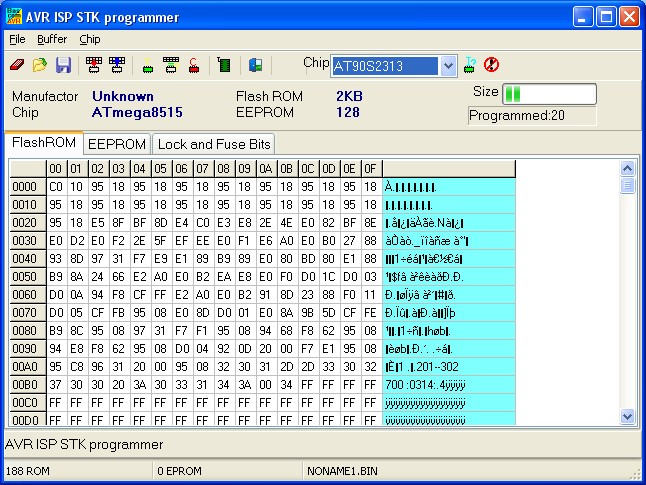
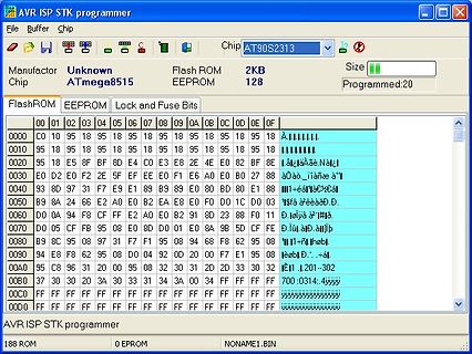
AVR ISP STK Programmer Software mit FlashROM Inhalt
95 18 E5 8F BF 8D E4 C0 E3 E8 2E 4E E0 82 BF 8E 0030 D0 E2 D0 F2 2E 5F EF EE E0 F1 E6 A0 E0 BD 27 88 0040 93 87 D0 31 F7 E9 E1 B9 B9 89 E0 BD 80 E1 88 0050 89 8A 24 66 E2 A0 E0 BE EA E8 E0 F0 D0 1C D0 03 0060 D0 9A F8 CF FF E2 A0 E0 B2 91 8D 23 88 F0 11 0070 D0 05 CF FB 95 08 97 31 F7 F1 95 08 94 68 F2 95 08 0080 B9 8C 95 08 97 31 F7 F1 95 08 94 68 F2 95 08 0090 94 E8 F8 62 95 D0 04 92 0D 20 00 F7 E1 95 08 00A0 95
in „LCD mit BASCOM an Port C“ · Mikrocontroller und Digitale Elektronik · · Screenshots
-
Datei
main.c
x); /*********************************************************** Initialisierung des USARTs des Atmega8 ***********************************************************/ #define F_CPU 4000000 #define USART_BAUD_RATE 19200 // 19200 #define USART_BAUD_SELECT (F_CPU/(USART_BAUD_RATE*16l)-1) void USART_Init(
in „Empfangsprobleme mit UART?!“ · Mikrocontroller und Digitale Elektronik ·
-
Datei
rundenzaehler.cc
------------------------------------------------ // Titel : myAVR Beispiel "Interrupt 0" für den ATmega8 //---------------------------------------------------------------------- // Funktion : LED wird über Taster eingeschalten // Schaltung : Taster1 an PORTD.2, LED's an PORTB.0-2 //---------------------------------------------------------------------- // Prozessor : ATmega8 // Takt : 3,6864 MHz // Sprache : C // Datum : 18.03.2004 // Version : 1.2 // Autor : Dipl. Ing. Päd. Alexander Huwaldt // Programmer : ... // Port : ... //----------------------------------------
in „Rundenzähler via Transponder“ · Mikrocontroller und Digitale Elektronik ·
-
 Bild
Bild
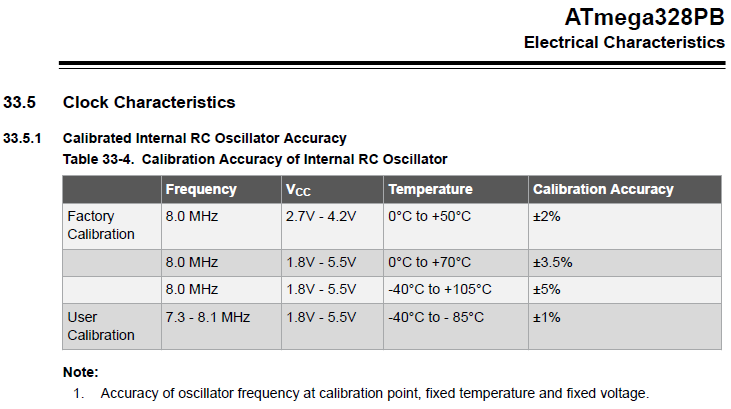
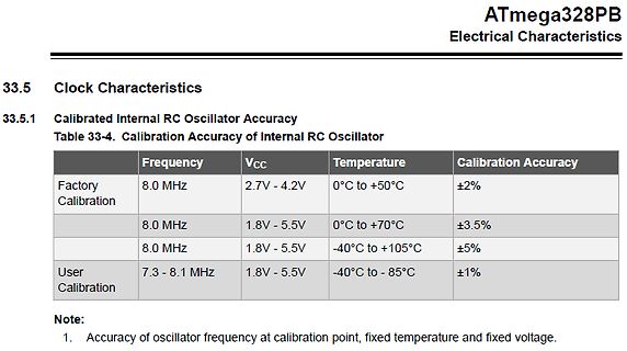
Tabelle der Kalibriergenauigkeit eines internen RC-Oszillators
ATmega328PB Electrical Characteristics 33.5 Clock Characteristics 33.5.1 Calibrated Internal RC Oscillator Accuracy Table 33-4. Calibration Accuracy of Internal RC Oscillator Frequency Vcc Temperature Calibration Accuracy Factory Calibration 8.0 MHz 2.7V - 4.2V 0°C to +50°C ±2% 8.0 MHz 1.8V - 5.5V 0°C to +70°C ±3.5% 8.0 MHz 1.8V - 5.5V -40°C to +105°C ±5% User Calibration 7.3 - 8.1 MHz 1.8V - 5.5V -40°C to -85°C ±1% Note: 1. Accuracy of oscillator
in „rpi <--> avr uart Übertragungsfehler bei Quarzbetrieb“ · Mikrocontroller und Digitale Elektronik · · Screenshots
-
Datei
main.asm
Created: 19.03.2025 15:33:59 ; Author : Andreas ; C:\Program Files (x86)\Atmel\Studio\7.0\packs\atmel\ATmega_DFP\1.7.374\avrasm\inc\m328Pdef.inc .device ATmega328P .EQU takt = 16000000 ; Systemtakt 16 MHz intern => 1 CPU clk = 62,5ns .def dummy = r17 ; Dummy verwendung ;***********************************
in „Frage: 328p und Timer2/GPIO in assembler“ · Mikrocontroller und Digitale Elektronik ·
-
 Bild
Bild
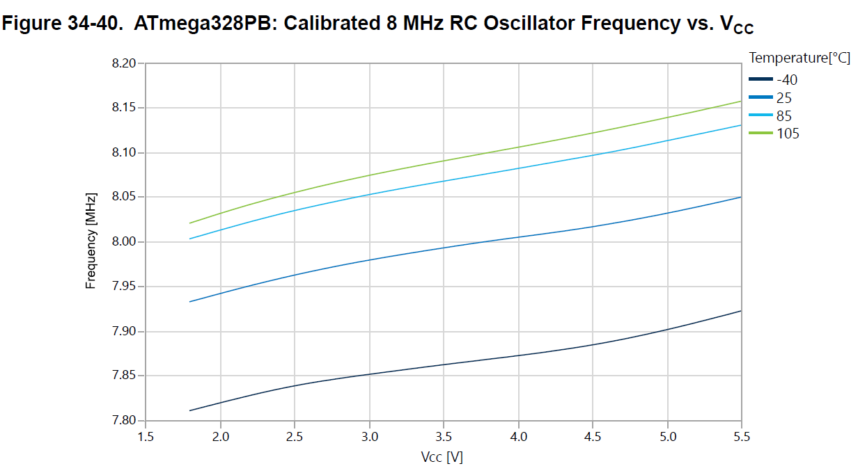
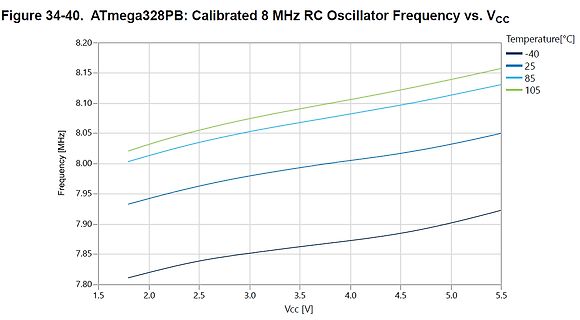
Diagramm der RC-Oszillatorfrequenz vs. VCC bei verschiedenen Temperaturen
Figure 34-40. ATmega328PB: Calibrated 8 MHz RC Oscillator Frequency vs. VCC Frequency [MHz] 8.20 8.15 8.10 8.05 8.00 7.95 7.90 7.85 7.80 Vcc [V] 1.5 2.0 2.5 3.0 3.5 4.0 4.5 5.0 5.5 Temperature[°C] -40 25 85 105
in „Suche Arduino kompatiblen Bootloader für ATmega8 mit 8Mhz intern“ · Mikrocontroller und Digitale Elektronik · · Diagramme
-
Datei
master.c
// // Anpassungen im makefile: // ATMega8 => MCU=atmega32 im makefile einstellen // lcd-routines.c in SRC = ... Zeile anhängen // #include <stdlib.h> #include <avr/io.h> #include <avr/delay.h> #define SS PB4 #define MOSI PB5 #define MISO
in „AD9833 mit SPI an MEGA32, output passt nicht“ · Mikrocontroller und Digitale Elektronik ·
-
Datei
LPH8731-3C.c
*/ 0x25, 1, 0x63, /* Contrast (interesting range for my display 0x5f...0x6f) */ /* color table for 8 bit "true color" mode */ 0x2d,20, 0x00,0x3,0x5,0x6,0x7,0x8,0x9,0xf, /* red 8 levels = 3 Bit */ 0x00,0x3,0x5,0x6,0x7,0x8,0x9,0xf, /* green 8 levels = 3 Bit */ 0x00,0x6,0x8,0xf, /* blue 2 levels = 2 Bit
in „LCD LPH8731-3C aus Siemens-Handys, Treiber“ · Mikrocontroller und Digitale Elektronik ·
-
PDF
dog_text.pdf
------------------------------------------------------------------------- dog_text.asm Page: 5 ; ATMega 8/48/88/168/162 .if (m48_88_168 ==1)|(m8==1)|(m162==1) spi_out: push r18 dog_enab out SPDR,r18 ; Start transmission of data (r16) spi_out10: in r18, SPSR ; Wait for transmission complete sbrs r18, SPIF rjmp spi_out10 dog_disab pop r18 ret .message "Target: ATMega8/48/88/168/162 SPI" .endif .endif ;use_spi_out ;---------------------------------------------------------------------------------------- ; Software SPI ; in r18 : Zeichen .if soft_spi== 1 spi_out:
in „DOGM162_163_4WIRE_SPI_3.3V_5.0V_Initialize_ASM“ · Mikrocontroller und Digitale Elektronik ·
-
PDF
MLSEcholot01_V02.pdf
Maximale Reflektordistanz MLS-Länge Ordnung (m) (Anzahl Impulse) (Zweier-Exponent) 0,5 127 7 1 255 8 2 511 9 4 1.023 10 8 2.047 11 15 4.095 12 30 8.191 13 60 16.383 14 Reichweiten von über 15m sind kaum zu erreichen ________________________________________________________________________________ MLSEcholot01
in „Hadamard Transformation“ · Digitale Signalverarbeitung / DSP / Machine Learning ·
-
Datei
sleep.h
devices. */ /* Also define some internal masks for use in set_sleep_mode() */ #if defined(__AVR_ATmega161__) #define _SLEEP_TYPE 5 #elif defined(__AVR_ATmega162__) || defined(__AVR_ATmega8515__) #define _SLEEP_TYPE 4 #elif defined(SM) && !defined(SM0) && !defined(SM1) && !defined(SM2) #define _SLEEP_TYPE
-
Datei
main.c
/* * ATMEGA328_clockgen.c * * Created: 02.01.2022 02:58:26 * Author : tboes Generate clock on PB0 / D8 */ #include <avr/io.h> #include <util/delay.h> void resetstring(void); void sendpulse(void); void sendcmd(
-
Datei
debug_error.asm
> } } 48c: 08 95 ret 0000048e <__vector_2>: #if defined(__AVR_ATmega8__) || defined(__AVR_ATmega88A__) || defined(__AVR_ATmega168__) ISR( INT1_vect ) #else # error MCU MODEL NOT SUPPORTED #endif // defined(__AVR_ATmega8__) || defined(__AVR_ATmega88A__) || defined(__AVR_ATmega168__) { 48e: 1f 92 push r1 490: 0f 92 push r0 492: 0f b6 in r0, 0x3f ; 63 494: 0f 92 push r0 496: 11 24 eor r1, r1 498: 8f 93 push r24 // just flag the IRQ (processing of status/data as well as resetting
in „Fehler bei einfacher Integer-Division?“ · Mikrocontroller und Digitale Elektronik ·
-
 Bild
Bild
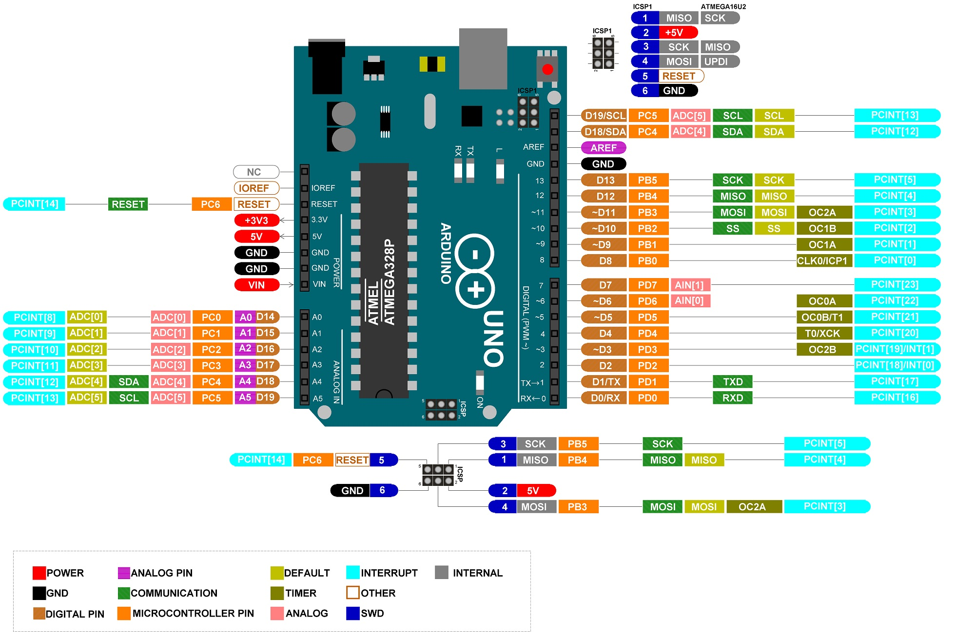
Pinbelegung eines Arduino Uno und ATmega16U2
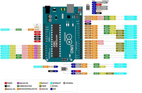
ICSP1 ATmega16U2 1 MISC 2 +5V 3 SCK MOSI 4 RESET UPDI 5 GND 6 GND NC IOREF RESET PC6 +3V3 VIN GND GND 5V GND 3.3V RESET IOREF NC RESET PC6 +5V SDA SCL ADC[5] ADC[4] SDA SCL PCINT[13] PCINT[14] D19 A0 D14 A1 D15
in „LCD-Display mit Arduino will nicht“ · Mikrocontroller und Digitale Elektronik · · Diagramme
-
 Bild
Bild
Schaltplan eines Mikrocontroller-basierten Komponenten-Testers
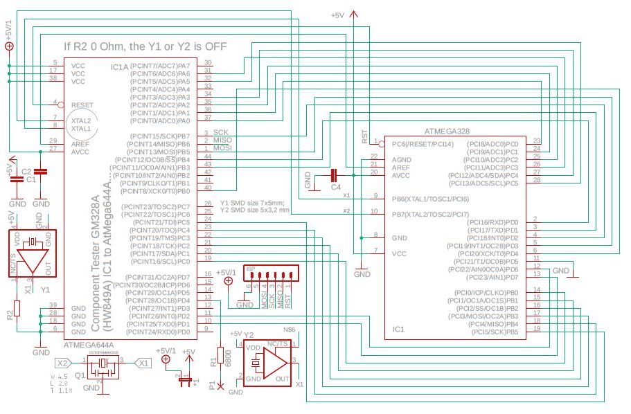
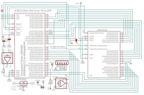
If R2 0 Ohm, the Y1 or Y2 is OFF +5V VCC RESET XTAL2 XTAL1 AREF AVCC GND NOCT OUT X1 R2 GND ATmega64A4 Component Tester GM328A (HW894A) IC1A (PCINT7/ADC7)PA7 (PCINT6/ADC6)PA6 (PCINT5/ADC5)PA5 (PCINT4/ADC4)PA4 (PCINT3/ADC3)PA3 (PCINT2/ADC2)PA2 (PCINT1/ADC1)PA1 (PCINT15/SCK)PB7 MISC MOSI (PCINT13/
in „Transistortester AVR“ · Projekte & Code · · Schaltpläne
-
Datei
pinbelegungpollin.txt
PC4 PC3 X PC2 PC1 PC0 PB7 PB6 PB5 PB4 PB3 PB2 PB1 PB0 PA7 PA6 PA5 PA4 PA3 PA2 PA1 PA0 Pinbelegung Atmega8 VCC GND VCC GND VCC GND AREF PD7 PD6 PD5 PD4 PD3 PD2 PD1 PD0 X X X X X X X X X X X PB5 PB4 PB3 PB2 PB1 PB0 X X X X PC5 PC4 PC3 PC2 PC1 PC0 Pinbelegung Atmega 2123 VCC GND VCC GND VCC GND AREF X PD6
in „AVR Evaluation Board von Pollin“ · Mikrocontroller und Digitale Elektronik ·
-
Datei
serial.c
/////////////////////////////////// void uart_init() { // UART Transmitter anschalten // Data mode 8N1, asynchron 4800 1MHZ UBRRH = 0; // Highbyte ist 0 UBRRL = 12; // Lowbyte ist 12 ( dezimal ) //UCSRB = (1 << TXEN) //gleiche wie UCSRB = 0x08; UCSRB = (1 << TXEN)|( 1 << RXEN ); // UART TX einschalten
in „Uart empfangen“ · Mikrocontroller und Digitale Elektronik ·
-
Datei
main.c
############################### // define cpu clock frequency if not already done /* #if (MCU == atmega8) #ifndef F_CPU #warning "F_CPU was not defined, now defining as 3.686.400Hz" #define F_CPU 3686400UL // crystal at 3.6864 Mhz #endif // F_CPU #else // (MCU == atmega644p) #ifndef F_CPU #warning "F_CPU
in „LCD funktioniert nur an Port D (ATmega644P)“ · Mikrocontroller und Digitale Elektronik ·
-
Datei
Fconverter.c
. Bei fehlendem Eingangssignal wird die niedrigste Frequenz ausgegeben. Das Programm ist für den ATmega48 geschrieben, laeuft aber auch ohne Aenderung direkt auf einem ATmega88. Beispielhaft wird hier in "main()" die Berechnung: frequenz = frequenz * 1.12246; durchgefuehrt, wodurch die Ausgangsfrequenz
in „Frequenz verlangsamen“ · Mikrocontroller und Digitale Elektronik ·
-
PDF
simulavr.pdf
Tracing :::::::::::::::::::::::::::::::::::::::::: 6 5 Graphic User Interface::::::::::::::::::::::::: 8 5.1 Details of the example GUI::::::::::::::::::::::::::::::::::::: 8 5.1.1 UpdateControl :::::::::::::::::::::::::::::::::::::::::::: 8 5.1.2 Net ::::::::::::::::::::::::::::::::::::::::::::::::::::
-
Datei
testl.h
global_h #define global_h #include <stdint.h> /* ISO C99 Integer types */ #include <avr/io.h> /* ATMEGA-32 I/O's */ #include <util/delay.h> /* delay Lib. */ /* ---- Define BIT Variablen --------------------------------------------------------------------------------- */ /* */ #define ON 1 /* digital
in „Taster abfragen - LED anschalten“ · Mikrocontroller und Digitale Elektronik ·
-
Datei
m168def.inc
" ;* Title : Register/Bit Definitions for the ATmega168 ;* Date : 2005-01-11 ;* Version : 2.14 ;* Support E-mail : avr@atmel.com ;* Target MCU : ATmega168 ;* ;* DESCRIPTION ;* When including this file in the assembly program file, all I/O register ;*
in „m168def.inc woher?“ · Mikrocontroller und Digitale Elektronik ·
-
Datei
m48def.inc
" ;* Title : Register/Bit Definitions for the ATmega48 ;* Date : 2005-11-04 ;* Version : 2.21 ;* Support E-mail : avr@atmel.com ;* Target MCU : ATmega48 ;* ;* DESCRIPTION ;* When including this file in the assembly program file, all I/O register ;* names
-
Datei
Test.asm
.include "m4809def.inc" .macro put #if defined (__ATmega4809__) .if @0 < $40 out @0,@1 .else sts @0,@1 .endif #else .if @0 < $60 out @0,@1 .else sts @0,@1 .endif #endif .endmacro ;---------------------- .macro puti ldi tmp0,@1 put @0,tmp0 .endmacro ;---------------------- .macro putiw #if defined (__ATmega4809__) .ifdef @0H ldi tmp0,low (@1) put @0L,tmp0 ldi tmp0,high(@1) put @0H,tmp0 .else ldi tmp0,low (@1) put @0+0,tmp0 ldi tmp0,high(@1) put @0+1,tmp0 .endif #else .ifdef @0H ldi tmp0,high(@1) put @
in „ATmega809 Timer CMP Interrupt funktioniert nicht“ · Mikrocontroller und Digitale Elektronik ·
-
PDF
3d_drucker_print_v16.pdf
PCINT17) (OC3A/AIN1)PE3 5 EN-E4 88 PK1(ADC9/PCINT17) (OC3A/AIN1)PE3 5 5 5 5 5 5 5 5 X-MIN 89 PK0(ADC8/PCINT16) (XCK0/AIN0)PE2 4 89 PK0(ADC8/PCINT16) (XCK0/AIN0)PE2 4 + + + V + + + + (TXD0)PE1 3 TX0 (TXD0)PE1 3 TX0 GND 4 3 2 + 5 6 7 1 79 PJ7 (RXD0/PCIN8)PE0 2 RX0 79 PJ7 (RXD0/PCIN8)PE0 2 RX0 5566-24 R
in „Eigenes 3D-Drucker Board - Viele Fragen“ · Mikrocontroller und Digitale Elektronik ·