-
Datei
RFM12BPCmd.h
RX-FIFO buffer // ef == 0 -> DATA (pin 6) and DCLK (pin 7) are used for data and data clock output #define EN_RX_BUF 0x0040 // [ b1..b0 ] -> select band // b1 b0 band[MHz] // 0 0 Reserved // 0 1 433 //
in „Rfm12B 686Mhz Bascom Testprogramm.“ · HF, Funk und Felder ·
-
Datei
startup_stm32f10x_hd.s
=_sbss b LoopFillZerobss /* Zero fill the bss segment. */ FillZerobss: movs r3, #0 str r3, [r2], #4 LoopFillZerobss: ldr r3, = _ebss cmp r2, r3 bcc FillZerobss /* Call the clock system intitialization function
in „STM32 Rücksprung defekt von IRQ“ · Mikrocontroller und Digitale Elektronik ·
-
Datei
Main_Adam.c
//Pins and Ports #define _LED_YE PB0 //Yellow LED #define _LED_RD PB1 //Red LED #define _LED_GN PB2 //Green LED (Heartbeat) #define _ATTN PB6 //ATTN-Signal to Eva (start new Measurement) #define _ACK PB7 //ACK-Signal from Eva (Measurement started) #define _RXD PD0 //UART from PC #define _IQ_RX PD5
in „ATTiny2313 läuft nicht immer an“ · Mikrocontroller und Digitale Elektronik ·
-
PDF
Koppler_Platine.pdf
U$6 VCC_A Vdd1 Vdd2 VCC_B Vi 0.1 uF Vo C8 501568-0409 VCC_B _ GND1 GND2 X1 D 15 pF0.1 uF Vcc X2 B G FOD0710 A Rx X3 D C5 C6 D Tx X4 N N GND G G U$2 U$3 _ _ X4 GND N N X3 Tx G 0.1 uF 15 pF A G X2 Rx FOD0710 D X1 Vcc C10
in „Schaltung mit Optokoppler FOD0710“ · Mikrocontroller und Digitale Elektronik ·
-
PDF
Messen.pdf
-------------------*/ UART_InitTypeDef UART_InitStructure; u8 TxBuffer[] = "UART1- 1,8,N,1@115.2k communication without flow control\n\r"; u8 RxBuffer[RxBufferSize]; u8 NbrOfDataToTransfer = TxBufferSize; u8 TxCounter = 0; u8 RxCounter = 0; GPIO_InitTypeDef GPIO_InitStructure; TIM_InitTypeDef TIM_InitStructure
in „ARM9 / STR9 Dev-Kit mit Ethernet/USB/CAN für 39,-“ · Mikrocontroller und Digitale Elektronik ·
-
Datei
msp_server.c
////////////////////////////////////////// uint8_t ch_status[MAX_SOCK_NUM]; /** 0:closed, 1:ready, 2:connected */ uint8_t txBuffer[TX_MAX_BUF_SIZE]; // TX Buffer for applications uint8_t rxBuffer[RX_MAX_BUF_SIZE]; // RX Buffer for applications uint8_t lastByte = 0; uint8_t readBufferPointer = 0; uint8
in „Send response (Action *Var)“ · Mikrocontroller und Digitale Elektronik ·
-
PDF
datasheet.pdf
, ±5% fO R±5% 3 80 dB Receiver Ultimate Rejection RULT 3 100 dB Sleep Mode Current IS 0.7 µA Power Supply Voltage Range V CC 2.2 3.7 Vdc Power Supply Voltage Ripple 10 mV P-P o Ambient Operating Temperature TA -40 85 C Notes
in „OPV mit niedriger Eingangskapazität“ · Analoge Elektronik und Schaltungstechnik ·
-
Datei
iotn841.h
#define TOV1 0 #define OCF1A 1 #define OCF1B 2 #define ICF1 5 #define TIMSK1 _SFR_IO8(0x0F) #define TOIE1 0 #define OCIE1A 1 #define OCIE1B 2 #define ICIE1 5 #define TIFR2 _SFR_IO8(0x10) #define TOV2 0 #define OCF2A 1 #define OCF2B 2 #define ICF2
in „Neue ATtinies 441 und 841“ · Mikrocontroller und Digitale Elektronik ·
-
Datei
main.asm
reti ;----------------------------------- ; main programstart and main routine main: ldi ZH,high(UART_RX_Received) ldi ZL,low(UART_RX_Received) ldi temp1,0x20 ; lade Leerzeichen ldi temp2,Rxsize ; write into RX-Buffer char -> space mainRam: st Z+,temp1 dec temp2 brne mainRam ldi ZH,high(SRAM_START) ldi
-
Datei
sms1.ASM
::::::::::::::::::::::::::::::::::::::::::::::::::::: ; Serial Baud Rate is 19200 baud using Timer 2 on 24 MHz Xtal MODE 1 ; 24000000/32 /39 = 19230 Baud ; 65536-39=65497 =FFD9 Serial_Init: MOV SCON,#01010000b MOV RCAP2H,#0FFh ; Reload value MOV RCAP2L,#0D9h MOV T2CON,#034h ; Baudrate for Tx and Rx
in „Simens S 35; AT-Befehle“ · Mikrocontroller und Digitale Elektronik ·
-
PDF
readme_210914.pdf
werden müssen. UART - Receiver --------------------------------------------------------------- pio_uart_rx_1_byte.py In der SDK ist ebenfalls ein asm_pio-Beispiel für einen UART-Receiver enthalten. Davon abweichend wird in den folgenden Variante das Startbit zusätzlich 2x getestet und es wird geprüft, ob
in „Spielereien mit asm_pio + MicroPython auf dem PI PICO“ · Projekte & Code ·
-
PDF
BC04_Manual.pdf
19.0 mA Standby Host connection - 38.4 40 µA Function Diagram PDFmyURL.com Schemetic File:BLK-MD-BC04-B DEMO schematic.pdf PDFmyURL.com Dimension PDFmyURL.com BC04-A Basic Connection To computer 1. Convert TTLlevel RS232 2. Module power supply 3.3 V 3. TX and RX connected to RX and TX To other devices 1. TX and RX connected to RX and TX 2. Module supply 3.3V Module into the AT test methods 1. Module power supply 3.3 2. Open HyperTerminal or other serial debugging tools 3. Open HyperTerminal or other serial debugging
in „HC-06 / HC-05 Bluetooth Modul“ · Mikrocontroller und Digitale Elektronik ·
-
PDF
TS80C51U2_ATMELCorporation.pdf
0000 D7h C8h T2CON T2MOD RCAP2L RCAP2H TL2 TH2 CFh 0000 0000 XXXX XX00 0000 0000 0000 0000 0000 0000 0000 0000 C0h SCON_1 SBUF_1 C7h 0000 0000 XXXX XXXX IP SADEN_0 SADEN_1 B8h X000 0000 0000 0000 0000 0000 BFh B0h P3
-
Datei
main.c
< CS10) | (1 << WGM12); TCCR2A = (1 << COM2A1) | (1 << COM2A0) | (1 << COM2B1) | (1 << COM2B0) | (1 << WGM20) | (1 << WGM21); TCCR2B = (1 << CS22); OCR0A = 128; OCR0B = 128; OCR1B = 128; OCR1A = 128; OCR2A = 128; OCR2B = 128; //
in „PWM per DMX regeln Atmega48“ · Mikrocontroller und Digitale Elektronik ·
-
Datei
Utikiteval.c
!!!!!!!!!!!!!!!!!!!!!!!!!!!!!!!!!!! */ #include <16F73.H> /* Pin definitions */ #define SFmode PIN_B0 #define PowerDown PIN_B2 #define PD 02 /* PIN_B2 */ #define CML PIN_A3 #define OUTPUT PIN_C2 #define Sync PIN_C3 #define SEL1 PIN_B5 #define SEL2 PIN_B4 #define SEL3 PIN_A5 #define SEL4 PIN_B1 #define
in „PT100 + SMT-UTI + ATmega8 (in C) = bin zu doof“ · Mikrocontroller und Digitale Elektronik ·
-
Datei
main_attiny.c
io_init(); // PD5 -> output -> low spi_init(); nrf24_init(); // initialize hardware pins nrf24_config(2,4); // channel #2, payload length: 4 SETBIT(PORTD, 5); /* Set the device addresses */ nrf24_tx_address(spi_tx_address); nrf24_rx_address(spi_rx_address); sei(); // Global Interrupts activate //usart_transmit_string
in „nrf24l01 sendet nicht“ · Mikrocontroller und Digitale Elektronik ·
-
Datei
t.c
*******************/ GPIO_InitTypeDef GPIO_InitStruct; // this is for the GPIO pins used as TX and RX USART_InitTypeDef USART_InitStruct; // this is for the USART1 initilization NVIC_InitTypeDef NVIC_InitStructure; // this is used to configure the NVIC (nested vector interrupt controller) /* enable APB2 peripheral clock for USART1 * note that only USART1 and USART6 are connected to APB2 * the other USARTs are connected to APB1 */ RCC_APB2PeriphClockCmd(RCC_APB2Periph_USART1, ENABLE); /* enable the peripheral clock for the pins used by * USART1, PB6 for TX and PB7 for RX */ RCC_AHB1PeriphClockCmd
in „STM32F405 clocktree und USART“ · Mikrocontroller und Digitale Elektronik ·
-
PDF
Arduino_-_PinMapping2560.pdf
PinMapp2560.zip) Arduino Mega 2560 PIN mapping table Pin Number Pin Name Mapped Pin Name 1 PG5 ( OC0B ) Digital pin 4 (PWM) 2 PE0 ( RXD0/PCINT8 ) Digital pin 0 (RX0) 3 PE1 ( TXD0 ) Digital pin 1 (TX0) 4 PE2 ( XCK0/AIN0 ) 5 PE3 ( OC3A/AIN1 ) Digital pin 5 (PWM) 6 PE4 ( OC3B/INT4 ) Digital pin 2 (PWM)
in „3D Drucker zum Laserengraver umbauen?“ · Mechanik, Gehäuse, Werkzeug ·
-
PDF
twist-200-EL_46736V000_112019_0-DRE_Rev-I_DE.pdf
wurden: fo min 710–m C min Produkt: RF Remote Control for Doors & Gates P 53 5 Typ: RM01-868, RM02-868-2, RM02-868-2-TIGA, T 3 23 17 RM03-868-4, RM04-868-2, RM08-868-2, RM01-434, RM02-434-2, RM03-434-4, RM04-434-2, 85 RX04-RM02-868-2-wi6, RX04-RM02-868-2-TT, 1 RX04-RM02-434-2, RX04-RM02-434-2-TT, 0 4 RX01
in „Relais für Abschaltverzögerung 24V gesucht“ · Haus & Smart Home ·
-
Datei
main.c
void chip_select(int RAM_bank) { // GPIOA->BSRR = (GPIOA->BSRR & ~(0x07)) | RAM_bank; // pins PA0-2 // GPIOA->BRR = ((GPIOA->BRR & ~(0x07)) & ~(RAM_bank)); switch (RAM_bank) { case 0: // 0b000 GPIOA->BRR |= (GPIO_Pin_2 | GPIO_Pin_1 | GPIO_Pin_0); break; case 1: // 0b001 GPIOA->BRR |= (GPIO_Pin_2 | GPIO_Pin_1); GPIOA->BSRR |= (GPIO_Pin_0); break; case 2: // 0b010 GPIOA->BRR |= (GPIO_Pin_2 | GPIO_Pin_0); GPIOA->BSRR |= (GPIO_Pin_1); break; case 3: // 0b011 GPIOA->BRR |= (GPIO_Pin_2); GPIOA->BSRR |= (GPIO_Pin_1 | GPIO_Pin_0); break; case 4: // 0b100 GPIOA
in „SPI-RAM-Bank an STM32F0-Discovery - write, kein read“ · Mikrocontroller und Digitale Elektronik ·
-
PDF
BluePillPlus_V10_SchDoc.pdf
1 2 3 4 5 6 7 8 3.3V BOOT0 CO1B2 P T R11 CO B GND PID10K PID10A PI12 PI11 PB2 R2 R3 V CO1 1K NC SWW1 GND PI32 PI31 GND PC0 PI10 GND P1PIW11 PIS10 蓝灯 0603 KECOW2 2 PIS10 10KΩ 2 1 100nF CD2 R4 1 3 PIW12 PPS
in „BluePill STM32 Bezugsquelle“ · Mikrocontroller und Digitale Elektronik ·
-
PDF
Rollix_Core_SRAM.pdf
Gnd (AD7) PA7 44 MA7 MA7 MAD7 CAP 22P NPO 1206 X2001 (A8) PC0 35 MA8 MA8 MA8 CRYSTAL 16MHZ M23ROXTAL2 (A9) PC1 36 MA9 MA9 MA9 R2010 R 4K7 KS 24 37 MA10 MA10 R2011 R 4K7 KS C2007 25 XTAL1 (A10) PC2 38 MA11 MA11 MA10 RxD_DEBUG Gnd 26 PD0 (SCL/ INT0) (A11) PC3 39 MA12 MA12 MA11 B TxD_DEBUG CAP 22P NPO 1206 27 PD1 (SDA / INT1) (A12) PC4 40 MA13 MA13 MA12 B RxD_BT PD2 (RXD1 / INT2) (A13) PC5 MA13 TxD_BT 28 PD3 (TXD1 / INT3) (A14) PC6 41 MA14 MA14 MA14 IRIN 29 PD4 (ICP1) (A15) PC7 42 MA15 MA15 MA15 LCD_#RD 30 PD5 (XCK1) EX_CLK 31 PD6 (T1) MA[0..15] 2 4 32
in „Externes SRAM Problem:“ · Mikrocontroller und Digitale Elektronik ·
-
PDF
2243913.pdf
that resistor networks RxHW bit. 2: When RxHW = “0”, the state of the TCON register RxA, RxW, and RxB bits is over- ridden (ignored). When the state of the RxHW bit returns to “1”, the TCON register RxA, RxW, and RxB bits return to controlling the terminal connection state. In other words, the RxHW bit does not corrupt the state of the RxA, RxW, and RxB bits. A o t W e r s s R B FIGURE 5-2: Resistor Network Shutdown Configuration. 2008-2013 Microchip Technology Inc. DS22107B-page 45 MCP454X
in „[V] 11St. SMD Dual Digital Poti - I2C Microchip MCP4561-103 10kOhm 256Steps Nonvolatile (8€)“ · Markt ·
-
PDF
22107B-1180063.pdf
that resistor networks RxHW bit. 2: When RxHW = “0”, the state of the TCON register RxA, RxW, and RxB bits is over- ridden (ignored). When the state of the RxHW bit returns to “1”, the TCON register RxA, RxW, and RxB bits return to controlling the terminal connection state. In other words, the RxHW bit does not corrupt the state of the RxA, RxW, and RxB bits. A o t W e r s s R B FIGURE 5-2: Resistor Network Shutdown Configuration. 2008-2013 Microchip Technology Inc. DS22107B-page 45 MCP454X
in „[V] 24St SMD Digital I2C / 256 Steps 5K Dual Poti Microchip MCP4561- 502E/MS (MSOP8) (alle 15€)“ · Markt ·
-
PDF
2243913.pdf
that resistor networks RxHW bit. 2: When RxHW = “0”, the state of the TCON register RxA, RxW, and RxB bits is over- ridden (ignored). When the state of the RxHW bit returns to “1”, the TCON register RxA, RxW, and RxB bits return to controlling the terminal connection state. In other words, the RxHW bit does not corrupt the state of the RxA, RxW, and RxB bits. A o t W e r s s R B FIGURE 5-2: Resistor Network Shutdown Configuration. 2008-2013 Microchip Technology Inc. DS22107B-page 45 MCP454X
in „[V] 44St. SMD Digital I2C / 256 Steps 10K Poti Microchip MCP4561- 103E/MS (MSOP8 Gehäuse)“ · Markt ·
-
PDF
2243913.pdf
that resistor networks RxHW bit. 2: When RxHW = “0”, the state of the TCON register RxA, RxW, and RxB bits is over- ridden (ignored). When the state of the RxHW bit returns to “1”, the TCON register RxA, RxW, and RxB bits return to controlling the terminal connection state. In other words, the RxHW bit does not corrupt the state of the RxA, RxW, and RxB bits. A o t W e r s s R B FIGURE 5-2: Resistor Network Shutdown Configuration. 2008-2013 Microchip Technology Inc. DS22107B-page 45 MCP454X
in „[V] 10St. Digitalpoti MCP4561-103E/MS 8MSOP orginalverpackt. (9€)“ · Markt ·
-
Datei
bootloader.cpp
_) UBRR0H = ( uint8_t ) ( ubrr << 8 ) & 0x0F; UBRR0L = ( uint8_t ) ( ubrr & 0xFF ); UCSR0A = _BVC(U2X0) | _BVC(MPCM0); UCSR0B = _BV ( RXEN0 ) | _BV ( TXEN0 ) | _BVC( RXCIE0 ) | _BVC(UCSZ02); UCSR0C = _BVC ( UMSEL01 ) | _BVC(UMSEL00) | _BV ( UCSZ01 ) | _BV ( UCSZ00 ) | _BVC(USBS0) | _BVC(UPM01) | _BVC
in „Suche Hilfe bei Optimierung Bootloader“ · Mikrocontroller und Digitale Elektronik ·
-
PDF
CanBus_RTC_Adapter.pdf
1 2 3 4 5 6 3 3 3 +3V3 3 3 38 VCC 3 + + +1 IC4 GND 15 JP3 J1P3 P$3SDA 16 SDA VBAT 14 3 4 TX0RTS DCLKOUT 3 2 1 1 SCL SQW 2 3 C6 5 TX1RTS D R5 JP1 JP3 J1P5 P$5SCL + 6 TX2RTS V A 10010 RX1BF IC2 A + 2 11 RX0BF
in „LinuxCNC mit rasberry-PI als IO-Interface -“ · PC Hard- und Software ·
-
Datei
enc28j60.c
( ERXFCON_UCEN + ERXFCON_CRCEN + ERXFCON_BCEN)); // Initialise the MAC registers BankSel(2); // select bank 2 SetBitField(MACON1, MACON1_MARXEN); // Enable reception of frames WriteCtrReg(MACLCON2, 63); WriteCtrReg(MACON3, MACON3_FRMLNEN + // Type / len field will be checked MACON3_TXCRCEN
in „Problem mit ENC28J60“ · Mikrocontroller und Digitale Elektronik ·
-
Datei
alf.c
char gammaCurve22[256] = { 0, 0, 0, 0, 0, 0, 0, 0, 0, 0, 0, 0, 0, 0, 0, 1, 1, 1, 1, 1, 1, 1, 1, 1, 2, 2, 2, 2, 2, 2, 2, 3, 3, 3, 3, 3, 4, 4, 4, 4, 5, 5, 5, 5, 6, 6, 6, 6, 7, 7, 7, 8, 8, 8, 9, 9, 9, 10, 10, 11, 11, 11, 12, 12, 13, 13, 13, 14, 14, 15, 15, 16, 16, 17, 17, 18, 18, 19, 19, 20, 20, 21, 21
in „12bit, 9-Kanal Soft-PWM für LEDs auf Mega16“ · Mikrocontroller und Digitale Elektronik ·
-
Datei
avreth-netlist.txt
between ICs sorted by IC pins of each IC / Connector - = not connected | AT ENC 10 FL 5 1 7 1 5 PB5 MOSI 2 6 8 1 PB6 MISO 3 8 2 4 PB7 SCK 4 3 -Reset (PullUp) 5 Vdd 9 56 Vcc +3.6 6 Vss 2 7 2 Gnd 7 XTAL2 (Xtal+C) 8 XTAL1 (Xtal+C) 9 8 PD0 RxD (Camera TxD) 10 10 PD1 TxD (Camera RxD) 11- PD2 Int0 12 4 PD3 Int1
in „winziger Webserver mit enc28j60+mega32“ · Mikrocontroller und Digitale Elektronik ·
-
Datei
rs485.c
/ //////////////////////////////////////////////////////////// // Aktivierung Ports etc. // RCC_APB2PeriphClockCmd(RCC_APB2Periph_GPIOA, ENABLE); // Port A RCC_APB2PeriphClockCmd(RCC_APB2Periph_GPIOB, ENABLE); // Port B RCC_APB2PeriphClockCmd(RCC_APB2Periph_GPIOC, ENABLE); // Port C RCC_APB2PeriphClockCmd
in „STM32 Tutorial“ · Mikrocontroller und Digitale Elektronik ·
-
PDF
jbl_es250pw_subwoofer_service_manual_40.pdf
NO ES250PW U w tB w tB ww lk o w lc om rC rec trC r. cke-sofwa acersofwa WHAM2 RX Jumpers and Options Jumpers/ WH4925/29 WH4927/31 Pin Name Components Pin Function Defaultconfig. Defaultconfig. Edge pin-16 J3 = 0R Pin
in „Synchronisiertes Wireless Audio (Digital)“ · Mikrocontroller und Digitale Elektronik ·
-
Datei
AIS.c
AIS_posrep.data.t_stamp <<= 1; AIS_posrep.data.t_stamp += *payload_in >> 1; } /*Convert Payload of position report (1,2 or 3) into separated vessel information*/ void ais_msg_process (void) { char buf34 [12]; utoa (list_depth, buf34, 10); glcd_print (0, 12, &buf34 [0]); if (AIS_UART.RX_complete != 0) { static uint8_t
in „Strukturarray wird überschrieben bzw. kann nicht vollständig beschrieben werden.“ · Mikrocontroller und Digitale Elektronik ·
-
PDF
Einstellbare_Laufzeitleitung_f_italsignale.pdf
IO1 IO2 P82B96 IC1a P82B96 CD4015 K1 STIFTLEISTEK2X4 D1 Bus SDA SDA TX D Q1 1 2 RX CAN-TX Q2 3 4 CLK Q3 5 6 RES Q4 7 8 IC2a K2 STIFTLEISTEK2X4 CD4015 RX TX Bus D3 SDA 1 2 Q1 D 3 4 Q2 SDA 5 6 Q3 CLK 7 8 Q4 RES IC1b CD4015 K3 STIFTLEISTEK2X4 SCL D2 Bus SCL TY CAN-RX D Q1 1 2 Q2 3 4 CLK Q3 5 6 RY RES Q4 7 8 IC2b K4 STIFTLEISTEK2X4 CD4015 K7 Bus D4 RY 1 2 Q1 D TY SCL SCL 3 4 Q2 5 6 Q3 CLK 7 8 Q4 RES DLYCLK VREF CANL
-
PDF
lpc2468_evb.PDF
GND GND D D Gezeichnet 10.07.08tpl LPC2468-Testboard Geprüft - - A Datum: 11.07.2008 Blatt * von * 1 2 3 4 5 6 7 8 1 2 3 4 5 6 7 8 A A VCC 2 COR16 10k 0 D1010 PVS_MISOO 3PID1SO0 RX PID1026 PVS_MOSII 28ID1SI29 TX PID10027 X5X5 B POVS_SCK 23ID1SCLK 46 1 B POVS_CSS 13ID1XCS3 LEFT PI390046 2PIX501 POVS_DREQ
in „Kann sich jemand mein Schema anschauen?“ · Mikrocontroller und Digitale Elektronik ·
-
Datei
startup_stm32f30x.S
=_sbss b LoopFillZerobss /* Zero fill the bss segment. */ FillZerobss: movs r3, #0 str r3, [r2], #4 LoopFillZerobss: ldr r3, = _ebss cmp r2, r3 bcc FillZerobss /* Call the clock system intitialization function
in „STM32 Takt Frage“ · Mikrocontroller und Digitale Elektronik ·
-
PDF
pins_arduino_1284.pdf
(D 7) PB7 8| |33 PA7 (AI 7 / D24) // RST 9| |32 AREF // VCC 10| |31 GND // GND 11| |30 AVCC // XTAL2 12| |29 PC7 (D 23) // XTAL1 13| |28 PC6 (D 22) // RX0 (D 8) PD0 14| |27 PC5 (D 21) TDI // TX0 (D 9) PD1 15| |26 PC4 (D 20) TDO // RX1/INT0 (D 10) PD2 16| |25 PC3 (D 19) TMS // TX1/INT1 (D 11) PD3 17|
in „FT800 TFT Display am ATmega 1284P geht nicht“ · Mikrocontroller und Digitale Elektronik ·
-
Datei
SPI_V2.vhd
rising_edge(CLK) then -- if sync='1' then -- Dataout <= SPI_Reg; -- end if; -- end if; --end process; RxFreigabe: process(CLK) begin if Reset = '1' then SPI_receive <= A; RxRdy <= '0'; else if rising_edge(CLK) then case SPI_receive is when A => if sync='1' then Dataout <= SPI_Reg; SPI_receive <= B; else SPI_receive <= A; end if; when B => RxRdy<='1'; SPI_receive <= C; when C => if OEN = '1' then SPI_receive <= D; end if; when D => RxRdy <= '0'; SPI_receive <= A; end case; end if; end if; end process; end Behavioral; -- SPI_V2.vhd
in „sorry nochma ne Frage zur Datenübernahme SPI/Schieberegister“ · FPGA, VHDL & Co. ·
-
Datei
usart.h
wenn ein ATMega128 benutzt wird #if defined (__AVR_ATmega128__) #define USR UCSR0A #define UCR UCSR0B #define UDR UDR0 #define UBRR UBRR0L #define USART_RX USART0_RX_vect #endif #if defined (__AVR_ATmega644__) || defined (__AVR_ATmega644P__) #define USR UCSR0A #define UCR UCSR0B #define UBRR UBRR0L #
in „µSD Karte Ulrich Radig Code funktioniert nicht mehr“ · Mikrocontroller und Digitale Elektronik ·
-
Datei
usart.h
wenn ein ATMega128 benutzt wird #if defined (__AVR_ATmega128__) #define USR UCSR0A #define UCR UCSR0B #define UDR UDR0 #define UBRR UBRR0L #define USART_RX USART0_RX_vect #endif #if defined (__AVR_ATmega644__) || defined (__AVR_ATmega644P__) #define USR UCSR0A #define UCR UCSR0B #define UBRR UBRR0L #
in „SD-Karte mit Mega644 & Software von Ulrich Radig“ · Mikrocontroller und Digitale Elektronik ·
-
Datei
example.c
weniger ... */ snd_byte(*msg.p++); /* ... und raus damit */ } } void InitUart(void) { static BYTE mem_rx[1000]; static BYTE mem_tx[1000]; /* die buffer initialisieren */ ASBrx=ASBCreate(mem_rx, sizeof(mem_rx)); ASBtx=ASBCreate(mem_tx, sizeof(mem_tx)); /* und den Rest des Uarts */ ... } struct sMyMsg { int a; int b; int c; int d; }; int main(void) { struct sASBMsg msg; struct sMyMsg myMsg; InitUart(); /* erstelle eine eigene Nachricht */ myMsg.a=1; myMsg.c=2; myMsg.b=3; myMsg.d=4; /* und sende sie */ ASBAddMsg(
in „Advance Serial Buffer“ · Mikrocontroller und Digitale Elektronik ·
-
PDF
TargetBoardSchematic.pdf
MCU. GREEN POWLED1 GROUND LED_G GROUND Provides cut pattern. For isolate TARGET. SS7 SS8 A A GROUND-E2OB GROUND TST_B(DNF) TST_B(DNF) TST_B(DNF) GND1 GND2 GND3 GROUND-E2OB GROUND Title Target Board for RX65N Schematic [Target MCU peri, Power] Size Document Number Rev 1.00 R20UT4164EJ0100 Date: Monday, February 05, 2018 Sheet 3 of 4 5 4 3 2 1 5 4 3 2 1 D D Renesas Confidential Emulator Circuit C C B B A A Title Target Board for RX65N Schematic [Emulator Circuit] Size Document Number Rev R20UT4164EJ0100 1.00 Date: Monday, February 05, 2018
in „RX65N BootMode funktioniert nicht“ · Mikrocontroller und Digitale Elektronik ·
-
Datei
startup_stm32f40xx.lst
00000000 DCD ETH_WKUP_IRQHandler ; Ethernet Wakeup through EXTI line 151 0000013C 00000000 DCD CAN2_TX_IRQHandler ; CAN2 TX ARM Macro Assembler Page 7 152 00000140 00000000 DCD CAN2_RX0_IRQHandler ; CAN2 RX0 153 00000144 00000000 DCD CAN2_RX1_IRQHandler ; CAN2 RX1 154 00000148 00000000 DCD CAN2_SCE_IRQHandler
in „Stm32f4 UART löst kein receive Interrupt aus“ · Mikrocontroller und Digitale Elektronik ·
-
PDF
ledpixel.pdf
:TSSOP-20_4.4x7.5mm_Pitch0.65mm +5V +5V 1 R 0 7 1µ 4 R U1B 8 k GND GND 5 5 R GND GND V 1 7 - 6 B V- B 4 LM358 C7 k 0 R 1 7 5 4n7 4 C GND GND GND +5V +5V +5V D1 PWR_FLAG LED_RGB_5050 P3 RX 3 TX 3 SWIM 1 LED_G 100 BC BA 2 2 T 2 G R1 6 R 1 I U R 1 1 O RESET# 3 P LED_R 130 RC RA R2 5 G 2 P1 P2 LED_B GC GA 100 4 3 GND GND GND R3 B C C +5V +5V +5V C2 C3 C4 100n 100n 22µ X1 X2 Sheet: / D File: ledpixel.sch D GND GND GND Hole Hole Title: Size: A4 Date: Rev: KiCad E.D.A. kicad 4.0.1
in „Projektidee RGB Pixel mit Touch“ · Mikrocontroller und Digitale Elektronik ·
-
 Bild
Bild
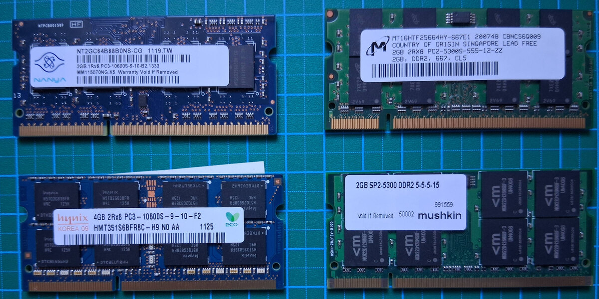
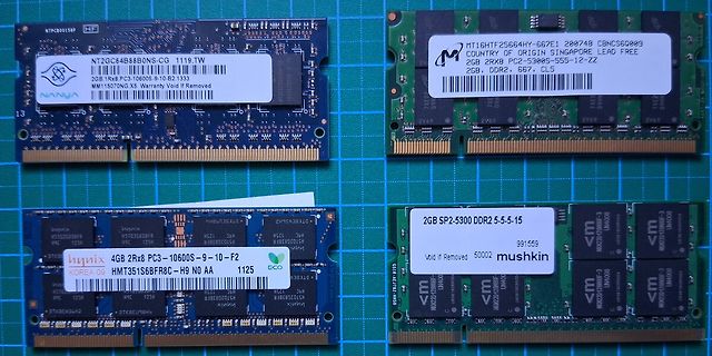
Vier DDR2 RAM Module auf blauem Untergrund
NT2GC64B8B0NS-CG 1119.TW 2GB 1Rx8 PC3-10600S-9-10-B2 1333 MM150TONG.XS MT6HTF25664HY-667E1 200748 CBNC56Q003 COUNTRY OF ORIGIN SINGAPORE LEAD FREE 2GB 2RX8 PC2-5300S-555-12-ZZ 2GB DDR2 667 CL5 2GB SP2-5300 DDR2 5-5-15 HMT31S68FRC-H9 00 AA 1125 4GB 2Rx8 PC3-10600S-9-10-F2 KOREA 09
in „[V]erschenke 4 ältere RAM-Module (1 x 4GB, 3 x 2GB) gegen Porto“ · Markt · · Fotos
-
PDF
prop_stamp_sheet.pdf
GND 7 G 6 BOE/ XI 28 C3 GND 18 7 RES/ XO 29 B 65100516121 10n GND 21 B P8X32A-Q44 H 2 FT232RL M Q 6 GND GND JP2 JP3 1 P0 P31 1 2 P1 P30 2 3 P2 P29 3 4 P3 P28 4 P4 P27 LM2937IMP-3.3 5 5 6 P5 P26 6 5V USB IN IN OUT OUT +3V3 7 P6 P25 7 + 8 P7 P24 8 JP1 C5 GND 9 GND +3V3 9 1 2 100n GND 10µ 10 GND 10 TX_USB 3 4 P31 RX_USB P30 C IC2 11 RST XI 11 C GND 12 GND 12 GND 13 P8 P23 13 +3V3 14 P9 P22 14 15 P10 P21 15 JP4 JP5 1 1 16 P11 P20 16 +3V3 +3V3 0 0 8 17 P12 P19 17 RX_USB 2 RX_USB
in „Propeller-Stamp“ · Mikrocontroller und Digitale Elektronik ·
-
PDF
OpenM128_Interrupts__1_.pdf
INT6_vect External Interrupt Request 6 9 0010 INT7_vect External Interrupt Request 7 10 0012 TIMER2_COMP_vect Timer/Counter2 Compare Match 11 0014 TIMER2_OVF_vect Timer/Counter2 Overflow 12 0016 TIMER1_CAPT_vect Timer/Counter1 Capture Event TIMER1_COMPA_vect 13 0018 Timer/Counter1 Compare Match A 14
in „OpenM128, eigene Hardware und RFM12-Modul“ · Mikrocontroller und Digitale Elektronik ·
-
PDF
Wave-2_Coaxial_PhoneLine__NetworkEval_Sept24_2018_UG.pdf
Rx C 88LX2730 ADC 2 Buttons AFE A text e HPF r 240MHz 88LX5153 RGMII Gigabit RJ-45 ETH h DAC 2 DBB PHY + E 88E1510 Magnetics V ADC 3 T SGMII B SPI1 e SFP Cage FO r Cable t E 2.5V 5V 3.3V 1.5V 1.05V LDO
in „Ethernet über 2adrige Telefonleitung. Idee: Billige Powerline Adapter für z.B. 24V umbauen. Mögli“ · Mikrocontroller und Digitale Elektronik ·
-
Datei
i2c-sample.asm
---------------- ; RAM Bank 0 0x20 - 0x6F ; --------------------------------------- CBLOCK 0x0020 i2c_index, i2c_error,i2c_temp R0L,R0H,R1L,R1H,R2L,R2H,R3L,R3H,R4L,R4H,i,j,wert,lsb,msb,msb1,x_old,y_old endc ; in diesen Buffer wird vom I2C IRQ geschrieben wenn daten ankommen ... #define RxBufferAdr 0x40
in „Mindesttaktzahl für I²C?“ · Mikrocontroller und Digitale Elektronik ·