-
 Bild
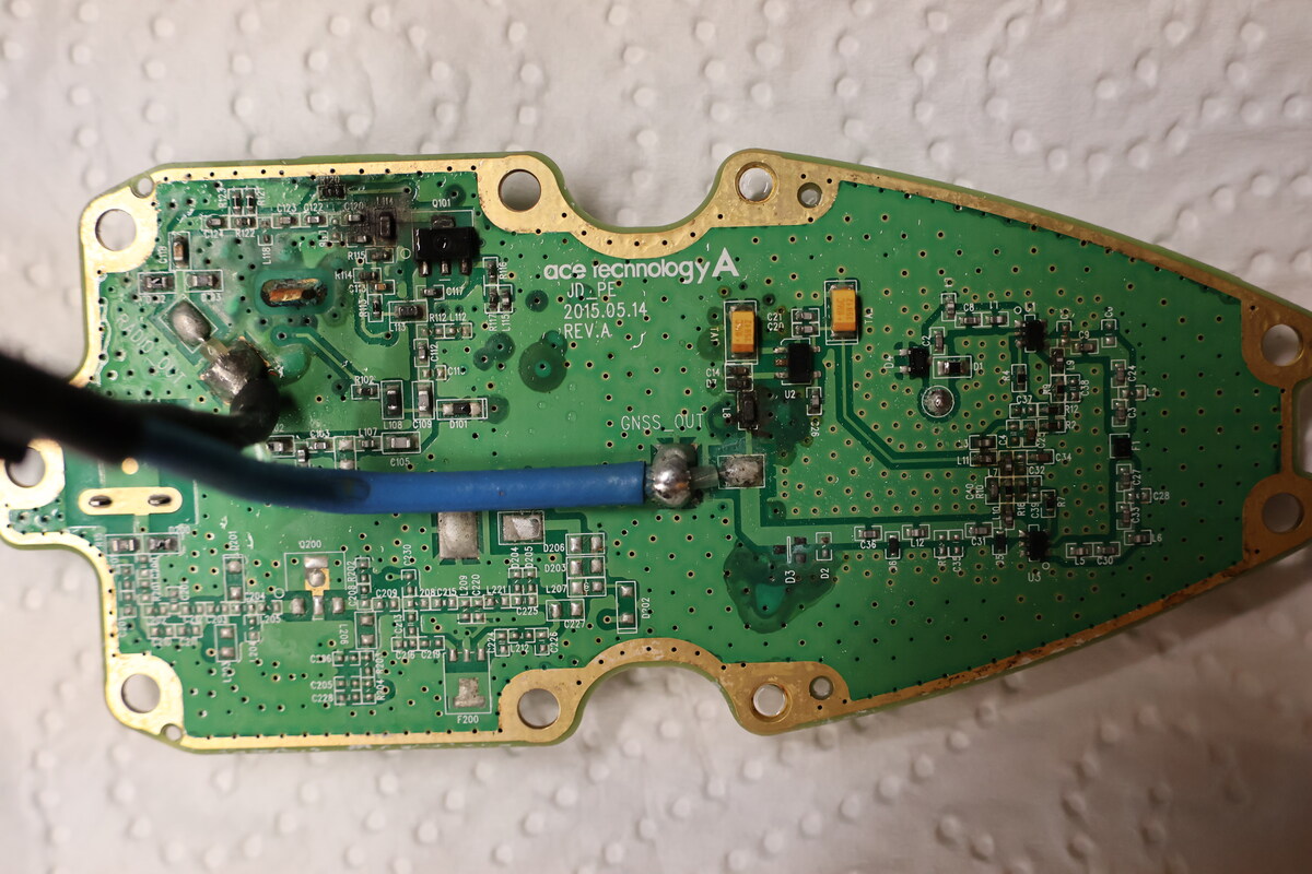
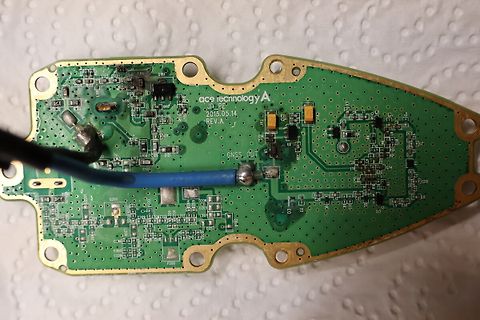
Foto einer Leiterplatte mit Kabelanschluss
ace technology A JD_PF 2015.05.14 REV.A GNSS_OUT C101 C102 C103 C104 C105 C106 C107 C108 C109 C110 C111 C112 C113 C114 C115 C116 C117 C118 C119 C120 C121 C122 C123 C124 C125 C126 C127 C128 C129 C130 C131 C132 C133 C134
in „Kia Ceed FM/GPS Antenne defekt“ · Platinen · · Platinenfotos
-
PDF
SSM2019.pdf
mV Maximum Capacitive Load Drive 5000 pF Short Circuit Current Limit I Output-to-Ground Short ±50 mA SC Output Short Circuit Duration Continuous sec GAIN Gain Accuracy RG= 10 kW T A 25∞C G – 1 R G 10 W, G = 1000 0.5 0.1 dB R G 101 W, G = 100 0.5 0.2 dB R G 1.1 kW, G = 10 0.5 0.2 dB R G , G = 1 0.1 0.2
in „Wie arbeitet der SM2019 Vorverstärker“ · Analoge Elektronik und Schaltungstechnik ·
-
PDF
Winstar320240bx.pdf
) 0.34 . . . . 6.5 2 4 8 1 28.41 115.18(AA) 6 4 . . 0 0 DOT SIZE 5 ) ) 200.0±10.0 SCALE 10/1 0 7 0 A A 0 4 1 ( 8 320*240 Dots 9 1 1 2 . 1 9 8 1.0 4-Ø3.5PTH 4-Ø6.0PAD 160.0±0.5 CCFL or LED B/L Graphic type 1. Built-in controller Epson-S1D13700 2. Built-in Negative Voltage generator Item Standard Value
-
PDF
red_beat.pdf
4Q1 C 47040V 2Q33 4007 333 22K 1U/50V C Q1 Q3 2C24 2R124 2R126 4R12 5401 D669 2Q16 2Q23 2Q22 5401 A968 A1943 A1943 473/100V 1C12 4Q2 1K 4R6 2R104 2C26 R17 C1815 22K 4Q1 4.7K 3.3K 3.3K 683/100V 300 1U/50V 2R102 2R101 4C3 4R1 120K 4R7 A1015 -56V 3.3K 4D4 4R8 JP1 4.7K XH-7 LED 8ohm/4ohn 250V 10A 4VR1
in „suche dringend schaltplan“ · Analoge Elektronik und Schaltungstechnik ·
-
PDF
AA400J_1000J.pdf
4Q1 C 47040V 2Q33 4007 333 22K 1U/50V C Q1 Q3 2C24 2R124 2R126 4R12 5401 D669 2Q16 2Q23 2Q22 5401 A968 A1943 A1943 473/100V 1C12 4Q2 1K 4R6 2R104 2C26 R17 C1815 22K 4Q1 4.7K 3.3K 3.3K 683/100V 300 1U/50V 2R102 2R101 4C3 4R1 120K 4R7 A1015 -56V 3.3K 4D4 4R8 JP1 4.7K XH-7 LED 8ohm/4ohn 250V 10A 4VR1
in „suche dringend schaltplan“ · Analoge Elektronik und Schaltungstechnik ·
-
Datei
utf8_funcs.txt
49: 1 50: 2 51: 3 52: 4 53: 5 54: 6 55: 7 56: 8 57: 9 58: : 59: ; 60: < 61: = 62: > 63: ? 64: @ 65: A 66: B 67: C 68: D 69: E 70: F 71: G 72: H 73: I 74: J 75: K 76: L 77: M 78: N 79: O 80: P 81: Q 82: R 83: S 84: T 85: U 86: V 87: W 88: X 89: Y 90: Z 91: [ 92: \ 93: ] 94: ^ 95: _ 96: ` 97: a 98: b 99
in „Cursorpositionierung, Farben und Codepage 437 Ausgabe im Linuxterminakl“ · Projekte & Code ·
-
PDF
ZM3102N.pdf
Power-On-Reset / Brown- Out Detection • Supply Voltage: 2.1V-3.6V • Power Consumption o TX@-5dBm = 24mA o TX@0dBm = 36mA o RX = 23mA o Power down/sleep mode = 2.5μA RF • Freq for 9.6kbps / 40kbps EU: 868.42 / 868.40MHz US: 908.42 / 908.40MHz HK: 919.82 / 919.80MHz NZ: 921.42 / 921.40MHz AUS:921.42 / 921.40MHz
in „Hat jemand Erfahrung mit Z-Wave Modulen (ZM3102)?“ · Mikrocontroller und Digitale Elektronik ·
-
PDF
ina105.pdf
0.01% FIGURE 14. Precision Gain = 1/2 Amplifier. ® INA105 8 Offset Adjust 6 7 8 Noise (60Hz hum) INA101AG 3 A1 4 Transducer or Analog Signal 10k 5 20k 10k R A 3 Output G 1 10 20k 10k 11 A2 10k 12 Noise (60Hz hum) Shield 100k 2 13 9 14 Common +V CC –VCC 3 INA105 2 5 6 1 FIGURE 17. Instrumentation Amplifier
in „Spannungs / Strom Wandler mit Offset versehen“ · Analoge Elektronik und Schaltungstechnik ·
-
 Bild
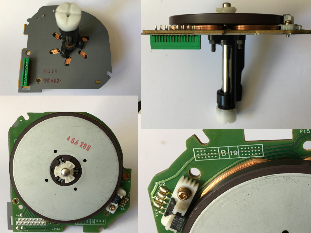
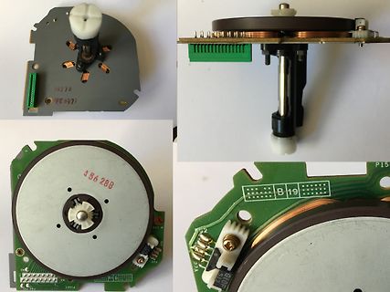
Nahaufnahmen eines Drehreglers mit Leiterplatte
3027 A FEK 3927 A 56 288 B 19 P15 F52 F53 F55 F56 F57 F58 F59 F60 F61 F62 F63 F64 F65 F66 F67 F68 F69 F70 F71 F72 F73 F74 F75 F76 F77 F78 F79 F80 F81 F82 F83 F84 F85 F86 F87 F88 F89 F90 F91 F92 F93 F94 F95 F96 F97 F98 F99 F100 F101 F102 F103 F104 F105 F106 F107 F108 F109 F110 F111 F112 F113 F114 F115 F116 F117 F118 F119 F120 F121 F122 F123 F124 F125 F126 F127 F128 F129 F130 F131 F132 F133 F134 F135 F136 F137 F138 F139 F140 F141
in „[V]Spezialmotor“ · Markt · · Fotos
-
PDF
behringer_nu3000.pdf
T13 D 10k 7 R182 R158 3 15 D52 4580 4k7 2k2 IN VB R78 IRFS4227 ES1D C66 C100 10u 6 1u/250 56p LIMIT-A 10u B 1n 1n 6E8 C145 0R197 C141 2 0 7 C102 R126 +15V 100p 100p 1 3 47p 6 14 9 D47 OUT_B -15V -15V R 3k92 VREF HO R123 k C101 ES1D +15V 3 H1 +15V 10k 20k 33p L5 +15V R183 R191 7 13 OCSET VS X10 1 C88
in „[S] Schematic Behringer NX3000“ · Analoge Elektronik und Schaltungstechnik ·
-
Datei
Timing_Summary_N_2.txt
bank1_data_frm_matrix_set_DCO1 AD9249_dig_data_interface/bank1_data_frm_matrix_set_DCO1 SLICE_X37Y84.A3 net (fanout=4) 0.414 AD9249_dig_data_interface/bank1_data_frm_matrix_set_DCO1 SLICE_X37Y84.A Tilo 0.061 AD9249_dig_data_interface/bank1_data_frm_matrix_read_DCO1 AD9249_dig_data_interface/_n0306_inv_SW0
-
Datei
IO-Error.txt
production [ 1770.635560] usb 2-1: Manufacturer: Jmicron Corp. [ 1770.635563] usb 2-1: SerialNumber: 00A123456789 [ 1770.637380] usb-storage 2-1:1.0: USB Mass Storage device detected [ 1770.638227] scsi host4: usb-storage 2-1:1.0 [ 1771.644259] scsi 4:0:0:0: Direct-Access ST1000LM 024 HN-M101MBB 0000 PQ
in „Externe Festplatte: Linux nicht erkannt, Windows problemlos“ · PC Hard- und Software ·
-
PDF
0900766b80060b32.pdf
/RM Page 5 of 19 HW-Description Rev. 4.0 1997-05-23 Pin Function Pin Function Pin Function 1 +5V 8 A3 15 D4 2 +12V 9 A2 16 D3 3 INT 10 A1 17 D2 4 NWR 11 A0 18 D1 5 NRD 12 D7 19 D0 6 NCS/CS 13 D6 20 ... 37 GND 7 ALE 14 D5 The maximum cable length of the parallel system is 30cm. 2.1.3 Active Antenna,
in „[V] Altes RFID Mifare Philips Eval Kit (1998)..“ · Markt ·
-
PDF
PT6312.pdf
, key scan circuit are all incorporated into a single chip to build a highly reliable peripheral device for a single chip micro computer. Serial data is fed to PT6312 via a three-line serial interface. It is housed in a 44-pin plastic LQFP Package
in „VFD Driver IC - Wieso negative Treiberspannung?“ · Mikrocontroller und Digitale Elektronik ·
-
PDF
STM86312.pdf
memory, a control circuit, and a key scan circuit. Serial data are input to the STM86312 through a three-line serial interface. This VFD controller/driver is ideal as a peripheral device for a single-chip microcomputer
in „STM86312 Funzt nicht“ · Mikrocontroller und Digitale Elektronik ·
-
PDF
epcos-inrush-overcurrent.pdf
overcurrent protection Type I I I I R R Approvals Ordering code R S Smax r R min (V = max (typ.) (V = Vmax mA mA A mA IECQ V = 440 V DC or V AC, V = 400 V DC or V AC, T = 120 °C (typ.), R = ±25 % max R ref R B750 123 245 4.0 4 25 13 X X B59750B0120A070 B770 64 127 2.8 3.0 70 45 X X B59770B0120A070 C751 87 173 4.0 3.5 50 26 X X B59751C0120A070 C752 69 137 4.0 3.5 80 42 X X B59752C0120A070 C753 56 112 4.0 3.0 120 63 X X B59753C0120A070 C754 50 100 4.0 3.0 150 68 X X B59754C0120A070 C771 49 97 2.8 2.5 120 76 X X B59771C0120A070 C772 43 86
in „Schaltzyklen bei PTC-Sicherungen?“ · Analoge Elektronik und Schaltungstechnik ·
-
PDF
epcos-inrush-overcurrent.pdf
overcurrent protection Type I I I I R R Approvals Ordering code R S Smax r R min (V = max (typ.) (V = Vmax mA mA A mA IECQ V = 440 V DC or V AC, V = 400 V DC or V AC, T = 120 °C (typ.), R = ±25 % max R ref R B750 123 245 4.0 4 25 13 X X B59750B0120A070 B770 64 127 2.8 3.0 70 45 X X B59770B0120A070 C751 87 173 4.0 3.5 50 26 X X B59751C0120A070 C752 69 137 4.0 3.5 80 42 X X B59752C0120A070 C753 56 112 4.0 3.0 120 63 X X B59753C0120A070 C754 50 100 4.0 3.0 150 68 X X B59754C0120A070 C771 49 97 2.8 2.5 120 76 X X B59771C0120A070 C772 43 86
in „Einschaltstrombegrenzung“ · Analoge Elektronik und Schaltungstechnik ·
-
PDF
Infineon_TLE9263QX.pdf
Software Development Mode the watchdog is OFF and therefore no reset and interrupt are generated due to a watchdog failure. Data Sheet 101 Rev. 1.1, 2014-09-26 TLE9263QX Supervision Functions Depending on the configuration, the WD_FAIL bits will be set after a watchdog trigger failure as follows: • In case
in „SBC für CAN/LIN bei einem 24V Bordnetz“ · Mikrocontroller und Digitale Elektronik ·
-
PDF
2SB1412.pdf
−0.05−0.1−0.2 −5 −101 −2 COLLECTOR CURRENT : I (A) C COLLECTOR CURRENT : I (A) C Fig.1 DC current gain vs collector current Fig.2 DC current gain vs. collector current V − 5 ) −5 t C Bl =40 ) TA=25°C ( ( C − 2 −25°C C −2 : : E 25 °C E −1 G − 1 A T L L −0.5 O −0.5 V V N N −0.2 T −0.2 IC B =50/1 T A 40/1 A U −0.1 30/1 R −0.1 A 10/1 T Ta=100°C S−0.05 S −0.05 R T R C−0.02 T L C −0.02 O−0.01 L C −2m−5m−0.01-−0.00.10.2−0.51 −2 −5−10 O −0.01 C −2m
in „Transistor durchgebrannt woher neuen?“ · Analoge Elektronik und Schaltungstechnik ·
-
PDF
rpb_electronic_taschenbuecher_gesamtverzeichnis_1970.pdf
Radio-Praktiker-Bücher Grundlagen Wellen und 14 Lehrgang Radiotechnik 22 24 Berufskunde Frequenzen Teil I und II 23a 25a Funktechniker Formelsammlung Daten- und Tabellen lernen 21 für den 68 Tabellen- 100 Formeln Formelrechnen 21a Radio-Praktiker 70 sammlung Rundfunk- Rundfunk- 3 empfangmit 27 Kleines Radiotechnik
in „Welche Bücher sind im "Radio-Praktiker Bücherei E-Book-Bundle 3 - Ton, Musik & Aufnahme"?“ · Offtopic ·
-
PDF
PSU_1228_Circuit_7d01.pdf
VR B 1N4148 22/1W C13223J Q5 R28 EGP10D 3 14 SWSPDT C1815 1K R27 ZD1 Q4 10K 4 13 输出电压调节 10K IN4734A A950 C12 102 5.6V/1W R26 5 12 R25 1K C17 Q5 J9 J2 R18 R24 3.3K A1015 RES1 RES1 6 11 VCC 104 Q6 R26 C15 18K 8.2K C1815 10K 1uF/35V 7 10 R19 CY ts 5 10K J3 VR4 METER VR5 1K C21 4 RES1 8 9 101 502 D11 R46
in „Kaltgerätekabel mit eingebauter Feinsicherung - gibs sowas?“ · Haus & Smart Home ·
-
PDF
PSU_1228_Circuit_0888.pdf
VR B 1N4148 22/1W C13223J Q5 R28 EGP10D 3 14 SWSPDT C1815 1K R27 ZD1 Q4 10K 4 13 输出电压调节 10K IN4734A A950 C12 102 5.6V/1W R26 5 12 R25 1K C17 Q5 J9 J2 R18 R24 3.3K A1015 RES1 RES1 6 11 VCC 104 Q6 R26 C15 18K 8.2K C1815 10K 1uF/35V 7 10 R19 CY ts 5 10K J3 VR4 METER VR5 1K C21 4 RES1 8 9 101 502 D11 R46
in „[Review] Funknetzteil K-PO KS28SW“ · HF, Funk und Felder ·
-
Datei
intTest.lst
; Define a output port 20: .equ pDir = DDRB ; Define a direction port 21: .equ pIn = PINB ; Define an input port 22: .equ bMyPinO = PORTB0 ; Define an output pin 23: .equ bDir0 = DDB0 ; Define a direction pin 24
in „attiny85 interrupt-behandlung“ · Mikrocontroller und Digitale Elektronik ·
-
 Bild
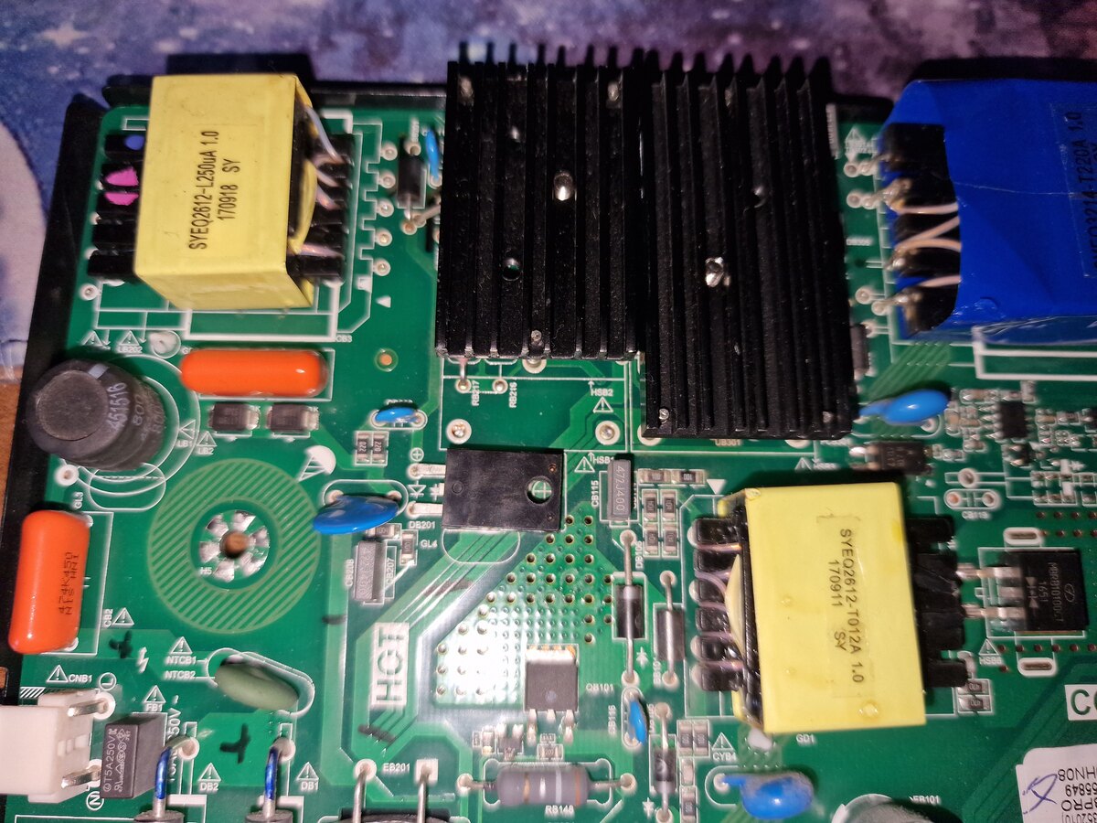
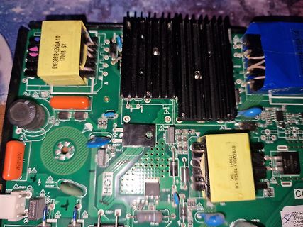
Nahaufnahme einer bestückten Leiterplatte mit Transformatoren und Kühlkörper
SYE02612-L250A 1.0 170918 SY, SYE02612-T012A 1.0 170911 SY, 451516, DS201, SL4, DS15, U2801, U2802, EB201, SB101, SB102, SB103, SB104, SB105, SB106, SB107, SB108, SB109, SB110, SB111, SB112, SB113, SB114, SB115, SB116
in „Fernseher Hintergrundbeleuchtung Defekt“ · Mikrocontroller und Digitale Elektronik · · Platinenfotos
-
 Bild
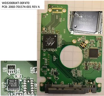
Leiterplatte mit integriertem Mikrocontroller und Komponenten
WD3200BJKT-00F4T0 PCB: 2060-701574-001 REV A 01AC P 89CY1DT CA8460581 3508 88B450-BH62 U9 C29 C62 U2 028 A743 C45 U20 L35 C18 C19 C20 C21 C22 C23 C24 C25 C26 C27 C28 C30 C31 C32 C33 C34 C35 C36 C37 C38 C39 C40 C41 C42 C43 C44 C45 C46 C47 C48 C49
in „Um welchen Chip könnte es sich handeln?“ · PC Hard- und Software · · Platinenfotos
-
 Bild
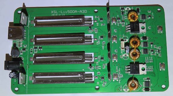
Grüne Leiterplatte mit mehreren Steckplätzen und Bauteilen
XSL-L11500A-A3D 2018-3-15 B4 B3 B2 B1 Q11 Q15 Q16 Q17 Q18 Q19 Q20 Q21 Q22 Q23 Q24 Q25 Q26 Q27 Q28 Q29 Q30 Q31 Q32 Q33 Q34 Q35 Q36 Q37 Q38 Q39 Q40 Q41 Q42 Q43 Q44 Q45 Q46 Q47 Q48 Q49 Q50 Q51 Q52 Q53 Q54 Q55 Q56 Q57
in „Liito-Kala Lii-500 Li-Ion Ladegerät defekt (nur noch Powerbank Mode möglich)“ · Analoge Elektronik und Schaltungstechnik · · Platinenfotos
-
 Bild
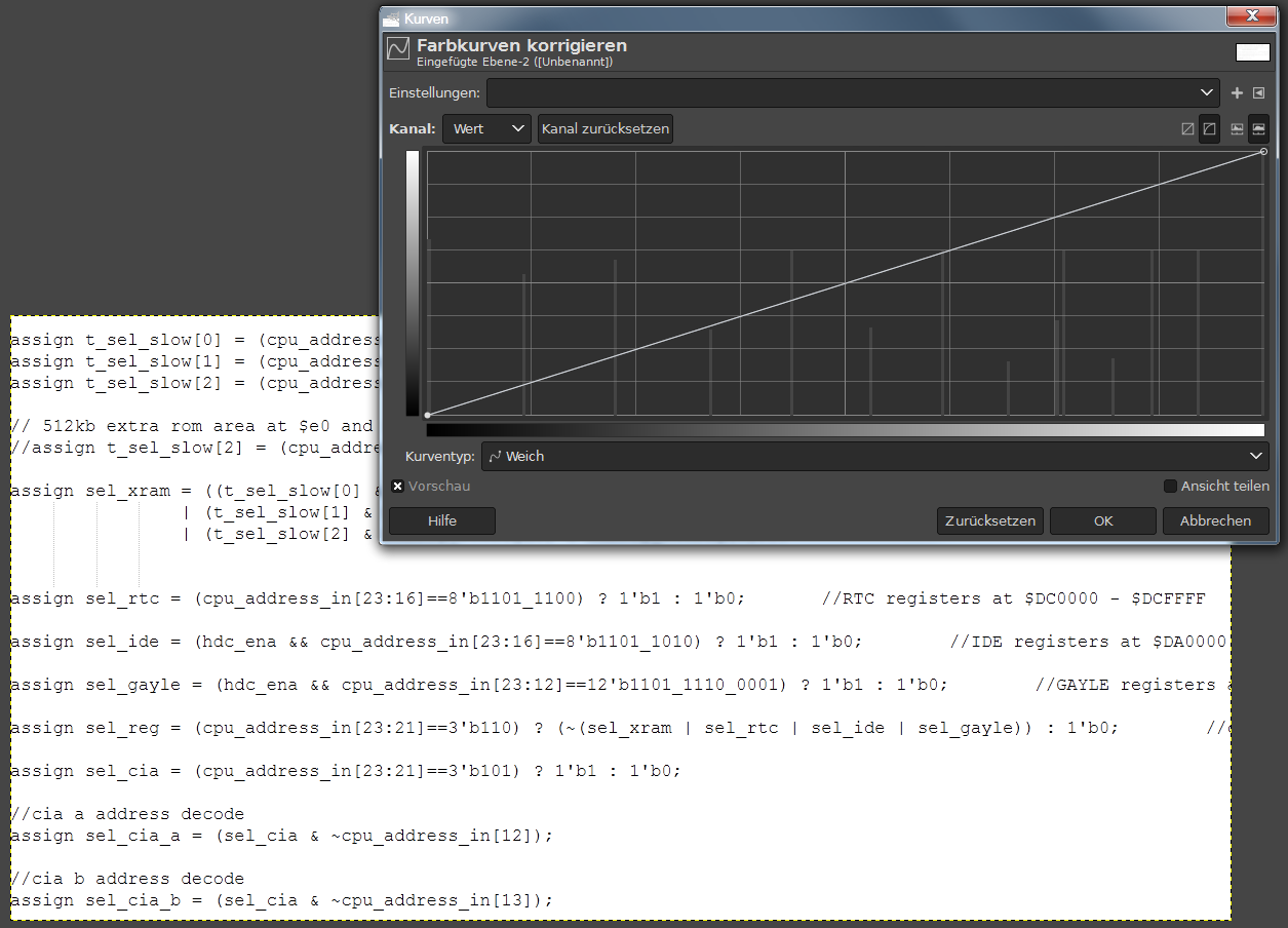
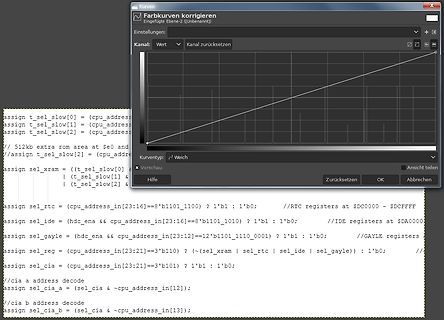
Software-Screenshot mit Programmcode und Diagramm
(~(sel_xram | sel_rtc | sel_ide | sel_gayle)) : 1'b0; assign sel_cia = (cpu_address_in[23:21]=='3'b101) ? 1'b1 : 1'b0; //cia a address decode assign sel_cia_a = (sel_cia & ~cpu_address_in[12]); //cia b address decode assign sel_cia_b = (sel_cia & ~cpu_address_in[13]);
in „Text als.JPG in Dokument Umwandeln?“ · PC Hard- und Software · · Screenshots
-
PDF
TM070RDH10_7_TIANMA.pdf
is 0.300 0.350 0.400 Note1 Chromaticity on 0.298 0.348 0.298 Note5 Green x y 0.521 0.571 0.621 x 0.101 0.151 0.201 Blue 0.051 0.101 0.151 y Note1 Uniformity U - 75 - % Note6 NTSC - 50 - % Note 5 Luminance(Without 2 Note1 TP) L 350 - cd/m Note7 Test Conditions: 1. F= 160 mA, V F9.6 V and the ambient temperature
in „LCD 800x480 ohne Display Controller was damit machen? oder hat jemand einen Controller dafür?“ · Mikrocontroller und Digitale Elektronik ·
-
PDF
JVC_rv-nb20b_Schema.pdf
,K1005 ,K1007,K1008,K1009,K1102,K1201:NQR0007-002X 4 NC 1 - 1 6 1 DGND 8 1 1 0 0 NC 2 K1101 2 2 A CN101 CN102 A OUT L 9 Q G 0 P Q NC 3 1 0 K1001 1 OUT_L 1 C 1 Audio Return 10 2 Audio_Rtn 2 0 P NC 4 1 0 K1201 3 OUT_R 3 C 1 4 OUT R 11 4 DG_SENS 4 0 0W K1002 1 2/ USB PW R 5 5 USB_PW R 5 R 1 K1003 C1007
in „JVC Boomblaster - 12V/230V unterschiedliche Bassstärke“ · Analoge Elektronik und Schaltungstechnik ·
-
PDF
toplevel_-_Behavioral__toplevel.vhd_.pdf
count <= 0; 97 end if; 98 end if; 99 if reset = '1' then -- RESET über Switch SW5 100 count <= 0; 101 LEDs_in <= X"18"; 102 sub_fertig <= '0'; 103 A <= 125000000; --Clock 125MHz 104 int <= to_integer(signed(DIP_Switches)); -- int ist der Wert der gewandelten DIP_Switches 105 if int = 0 then -- wenn
in „VHDL-Code strukturieren (Untermodule) Aber WIE?“ · FPGA, VHDL & Co. ·
-
Datei
RC5_AVR.asm
; RC5-Unterprogramm RC5.ASm ; nach einer Vorlage von Olaf Kaluza ;PC .equ $01 ;Cnt .equ $0A3 ;Kon .equ $0A4 ;Adr .equ $0A5 ;Tas .equ $0A6 ; .org $101 RC5_INT: push r23 push r24 push r25 push r26 push r27 clr r24 clr r25 clr r26 clr r27 rcall w444 ;warten 1/4 eines Biphasenbits sbic portd,2
-
Datei
main.c
uint8_t pinstate; volatile uint8_t start_flag; volatile uint8_t fifo[64]; void init_timer0(void){ TCCR0A |= (1<<WGM01); //CTC TIMSK |= (1<<OCIE0A); //compareA interrupt enable OCR0A = (counter_compare-1); TCCR0B |= (1<<CS01); //start timer0 w/ prescaler 8 } int main(void) { uint8_t i; uart_init(); uart_puts_p
in „Manchester Dekodieren“ · Mikrocontroller und Digitale Elektronik ·
-
PDF
2401283.pdf
2.BLOCK DIAGRAM 3. MECHANICAL SPECIFICATIONS ITEM SPECIFICATIONS UNIT REMARK DIMENSIONAL 159.4(W)×101.0(H)×13.0MAX.(T) OUTLINE mm *REFERENCE VIEWING AREA 124.0(W)×70.0(H) EFFECTIVE V/AREA 119.97(W)×63.97(H) NUMBER OF DOTS 240(W)×128(H) - DIMENSIONAL DOT PITCH 0.50(W)×0.50(H) mm OUTLINE DOT SIZE 0.47
in „Displaykompatibiltät?“ · Mikrocontroller und Digitale Elektronik ·
-
PDF
VHF-COMM.1984.3.pdf
beaccommod'llcd on Ihe ground sidof Ihe boatbelw H nIhe leedlhrough capacilo n atheground surlllce preamplifier 101 maximum gain. II possible. which saves one having 10 provide the gale lrimmer C 2 - and possibly trimmer Cs vol1age supply wnh a time delay. The ceeo should bo corrected later on a noise-ligu,e vantageol
-
PDF
ForumLNG_V101.pdf
??? D9 R14 680R 3V9 GRN E4 AC4 Unless otherwise specified, all values are as follows: PCB Name: N/A Title resistor values are in Ohms, i.e. 0R47, 5R6, 220, 5K6, 22K PCB Nr. ForumDualLabPow erSupply A N/A A capacitor values are in Microfarads, i.e. 220p, 0u1, 2u2, 33 PCB Type: Scale: Used in Repl.for
in „puff Peng und Magic smoke, Labornetzteil.“ · Analoge Elektronik und Schaltungstechnik ·
-
PDF
ForumLNG_V102.pdf
??? D9 R14 680R 3V9 GRN E4 AC4 Unless otherwise specified, all values are as follows: PCB Name: N/A Title resistor values are in Ohms, i.e. 0R47, 5R6, 220, 5K6, 22K PCB Nr. ForumDualLabPow erSupply A N/A A capacitor values are in Microfarads, i.e. 220p, 0u1, 2u2, 33 PCB Type: Scale: Used in Repl.for
in „puff Peng und Magic smoke, Labornetzteil.“ · Analoge Elektronik und Schaltungstechnik ·
-
PDF
ForumLNG_R103.pdf
SNS+ AC3 Gl1 -12V ??? GRN E4 AC4 Unless otherwise specified, all values are as follows: PCB Name: N/A Title resistor values are in Ohms, i.e. 0R47, 5R6, 220, 5K6, 22K PCB Nr. ForumDualLabPow erSupply A N/A A capacitor values are in Microfarads, i.e. 220p, 0u1, 2u2, 33 PCB Type: Scale: Used in Repl.for
in „puff Peng und Magic smoke, Labornetzteil.“ · Analoge Elektronik und Schaltungstechnik ·
-
PDF
KTY81.pdf
125 °C (mA) 4 100 °C 8 3 75 °C 50 °C 2 25 °C 0 °C 4 −25 °C −50 °C 1 0 0 10−1 1 I (mA) 10 −50 0 50 100 150 cont T (°C) amb To keep the temperature error low, an operating current of cont 1 mA is recommended for
in „Spannungsquelle für KTY - gegeneinander entkoppeln?“ · Analoge Elektronik und Schaltungstechnik ·
-
PDF
MAX44009.pdf
800ms. See Table 7. Table 7. Integration Time TIM[2:0] INTEGRATION COMMENTS TIME (ms) 000 800 This is a preferred mode for boosting low-light sensitivity. 001 400 — 010 200 — 011 100 This is a preferred mode for high-brightness applications. 100 50 Manual mode only. 101 25 Manual mode only. 110 12.5 Manual
in „Helligkeitssensor Threshold festlegen“ · Mikrocontroller und Digitale Elektronik ·
-
PDF
typofix.PDF
.f,i Bestell-Nr. F0Ll0holbfen 12p 101 t12 Grofischer Speziolbetriebs.kicbd.' voo Typofix-Vertrieb10Dresden, AltenzellerStroße50 ö o A A A A A A B B B B B C C C C C D D D D D D D E E E E E E : : 9 ' ö i:3 E E E E E E F F F F F F G G G G
in „Überätzt??? + Entsorgung von gebrauchten NaPS“ · Platinen ·
-
PDF
MM-Fuses-Fast-Spec.pdf
Rating ColdOhms A Sec. MIL-STD-202F Method 101D, Test Condition B D E 216.050P .050 250 15.90 0.00019 A U 216.063P .063 250 10.45 0.00054 D F 216.080P .080 250 7.885 0.00084 A E 216.100P .100 250 5.793 0.00450 PHYSICAL
in „Schmelzsicherung wählen“ · Analoge Elektronik und Schaltungstechnik ·
-
PDF
MM-Fuses-Fast-Spec.pdf
Rating ColdOhms A Sec. MIL-STD-202F Method 101D, Test Condition B D E 216.050P .050 250 15.90 0.00019 A U 216.063P .063 250 10.45 0.00054 D F 216.080P .080 250 7.885 0.00084 A E 216.100P .100 250 5.793 0.00450 PHYSICAL
in „20x5mm Sicherung mit Granulat?“ · Analoge Elektronik und Schaltungstechnik ·
-
Datei
TM1637Display.h
>TM1637Display.h</strong> </div> </div> <div class="commit-tease"> <span class="right"> <a class="commit-tease-sha" href="/avishorp/TM1637/commit/8501ae145047b53a24a6d7dba7a42b2cf9969fd6" data-pjax> 8501ae1 </a> <time datetime="2014-01-16T07:06:04Z" is="relative-time">Jan 16, 2014</time> <
in „7-Segmentanzeige an Atmega32“ · Mikrocontroller und Digitale Elektronik ·
-
PDF
PCF8583.pdf
3 2 1 0 memory location 08 reset state: 0000 0000 timer function : 000 no timer 001 hundredths of a second 010 seconds 011 minutes 100 hours 101 days 110 not used 111 test mode, all counters in parallel (factory use only) timer interrupt enable : 0 timer flag, no interrupt 1 timer flag, interrupt clock
in „RTC PCF8583 einen Interrupt ausloesen“ · Mikrocontroller und Digitale Elektronik ·
-
PDF
PCF8583_5_rtc_real_time_clock.pdf
3 2 1 0 memory location 08 reset state: 0000 0000 timer function : 000 no timer 001 hundredths of a second 010 seconds 011 minutes 100 hours 101 days 110 not used 111 test mode, all counters in parallel (factory use only) timer interrupt enable : 0 timer flag, no interrupt 1 timer flag, interrupt clock
-
PDF
PCF8583P.pdf
3 2 1 0 memory location 08 reset state: 0000 0000 timer function : 000 no timer 001 hundredths of a second 010 seconds 011 minutes 100 hours 101 days 110 not used 111 test mode, all counters in parallel (factory use only) timer interrupt enable : 0 timer flag, no interrupt 1 timer flag, interrupt clock