-
PDF
Schaltung.pdf
5V 3 GND SYNC GND R? 4 EN PG 13 1M 2 C? R? 2N3906 R? 10n 150 Q? VCC C? C? 3 VIN SW 14 PWR2.5 3k3 MOSFET-P 100n 10u 2 15 L? C? U? VIN SW 6.8u C? 10uF R? D? 1 6 R? 1 16 22u 2k7 Diode 1N4004 2 VIN SENSE 5 470k GND GND PGND PGND D? GND GATE LED0 3 CTL STAT 4 GND GND GND U? LTC4412 TPS62112 GND GND 5 THI
in „Kurz vorm Verzweifeln“ · Analoge Elektronik und Schaltungstechnik ·
-
Datei
Mikrocontroller_du_kleiner_Chaot_-_Lyrics.txt
wie er ein Gehäuse aus Lego und Kupfer fräst, dazwischen schickt Des|ntegrator Memes von kaputten MOSFETs. [verse] Wolfgang spielt Akkordeon auf einem Relais, das klingt wie Ska, Ove tanzt Breakdance auf Breadboards – kurzschluss-verdreht, doch wunderbar! Mani, Johnny, Cyblord, Christoph, Des|ntegrator
in „Neues aus der KI“ · Offtopic ·
-
PDF
FDP060AN08A0.pdf
F D P 0 October 2013 0 A N FDP060AN08A0 / FDB060AN08A0 0 A ® 0 N-Channel PowerTrench MOSFET 75 V, 80 A, 6 mΩ F D Features Applications B 0 • RDS(on) 4.8 mΩ ( Typ.)GS= 10 V,DI = 80 A • Synchronous Rectification for ATX / Server / Telecom PSU A • Q G(tot)3 nC ( Typ.) GS= 10 V • Battery Protection
in „Simulation IR2183 Halbbrückentreiber“ · Analoge Elektronik und Schaltungstechnik ·
-
PDF
USB-Layout.pdf
VREGO N-channel VBUS 4.7 k VDD P-channel 6.8 k VBAT Figure 5.1. USB Battery Power Switch The two MOSFETs used in this circuit are an FDC6420C which contains one N-channel and one P-channel MOSFET. USB VBUS is used to control the switching transistors. When VBUS is present, the N-channel FET is switched
-
PDF
Frequenzumrichter.pdf
BeidenunipolarenTransistorenhatsichderPower-MOSFETdurchgesetzt.ImUnterschied zum anfänglichen Feldeffekttransistor besitzt der MOSFET ein isoliertes Gate; damit ist eine leistungslose Steuerung wie bei der Elektronenröhre möglich. Eine Weiterentwicklung des MOSFET ist der VMOS-FET mit V-förmiger Gatezone. Damit vergleichbar ist der
in „Ersatz für G4PC30F IGBT Transistor“ · Analoge Elektronik und Schaltungstechnik ·
-
PDF
EG50.pdf
gewünschte Betriebsart wird über von außen zugängliche Jumper ausgewählt. Durch Verwendung von moderner MOSFET-Technologie wird ein Wirkungsgrad von bis zu 95% erreicht. Technische Daten Bestell-Code EG 50 Betriebsspannung [VDC] 11 – 70 Nennstrom [A] 10 Max. Strom [A] 20 Taktfrequenz der Endstufe [kHz] 49 Wirkungsgrad
in „Unterschied zwischen I*R- und Spannungsregelung“ · Analoge Elektronik und Schaltungstechnik ·
-
 Bild
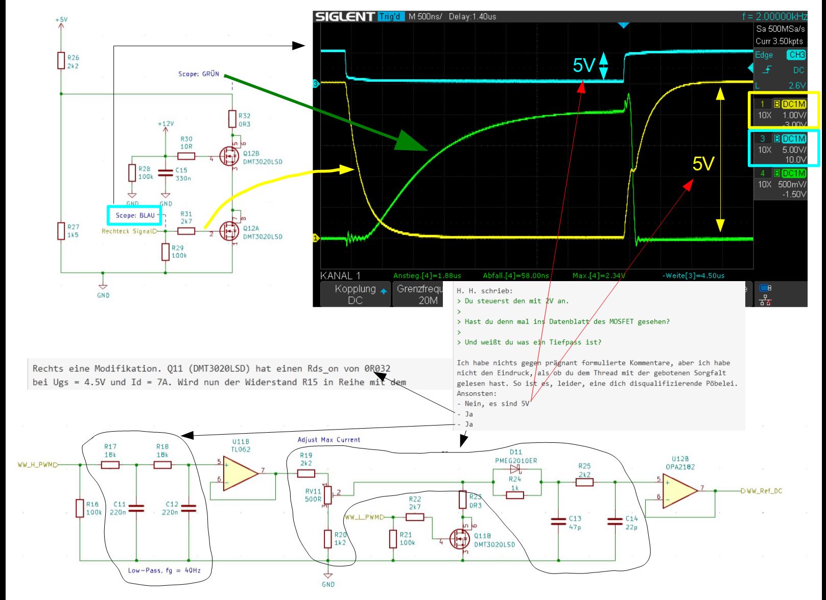
Schaltplan mit Oszilloskop-Screenshot und Forentext
Kopplung 20M Grenzfrequ H. schrieb: Du steuerst den mit 2V an. Du hast denn mal ins Datenblatt des MOSFET gesehen? Und wylst du ein Tiefpass? Ich habe nichts prägnant formulierte Kommentare, aber ich nicht den Eindruck, als ob du das Thema mit der gebotenen Sorgfalt behandelst. R17 10R R18 10R U118 TL062
in „Unerwünschter Peak beim Ausschalten eines Kleinsignal-MOSFET“ · Analoge Elektronik und Schaltungstechnik · · Screenshots
-
PDF
Schwingkond-53278649.pdf
point, of the input transistors. Most ofthe early electrometer amplifier designs 22 employed either MOSFET or bipolar-compatible JFET input stages [1,3,4,6]. The gate of a MOSFET is low leakage by design but it requires diodes for protection against overvoltage conditions. These protection diodes have the
in „DC-Messverstärker (Chopper) mit Kapazitätsdioden (diskret)“ · Analoge Elektronik und Schaltungstechnik ·
-
PDF
kicad_8450_dcm_liste_neu_v3.pdf
Q_PJFET_SDG Transistor P-JFET (general) Q_PJFET_SGD Transistor P-JFET (general) Q_PMOS_DGS Transistor P-MOSFET with substrate diode (general) Q_PMOS_DSG Transistor P-MOSFET with substrate diode (general) Q_PMOS_GDS Transistor P-MOSFET with substrate diode (general) Q_PMOS_GDSD Transistor P-MOSFET with substrate diode, drain connected to mounting plane (general) Q_PMOS_GSD Transistor P-MOSFET with substrate diode (general) Q_PMOS_SDG Transistor P-MOSFET with substrate diode (general) Q_PMOS_SDGD Transistor P-MOSFET with substrate diode, drain connected to mounting plane (general) Q_PMOS_SGD
in „KiCAD Eeschema, Bibliotheksdokumentation *.dcm als PDF-Datei“ · Platinen ·
-
PDF
C1.pdf
Spannungsversorgung 4. Hinweise - Prozessor Attiny84A SSU 1MHz, Spannungsregler LD50, N-Channel MOSFET FDD8647L - Code mit Arduino 1.8.12 - Grösse/mm HBT 13 30 53 - Wago Schraubklemmen - Minus wird geschaltet - Stromaufnahme ohne externe Last ~10mA bei 12VDC ACHTUNG: Das Modul ist ausgelegt für den
in „Motorrad: Verbraucher automatisch von Batterie trennen“ · Fahrzeugelektronik ·
-
PDF
USB-Datenspion_II_Hardware.pdf
LED Ansteuerung Status (Link Aktiv / Speed / (Douplex)) 1x SD-Card: Card Spannung Ein / Aus über MOSFET WR Erkennung CardIn Erkennung Bestückungsposition so dass die Karte im Gehäuse ist oder aus dem Gehäuse heraus schaut, oder dass eine Micro-SD Card verwendet werden kann. 1x Goldcap / Batt: Uhr (Quarz
in „Mehrere serielle Schnittstellen abfragen“ · Mikrocontroller und Digitale Elektronik ·
-
Datei
main.c
Tiefentladeschutz Tauchlampe * Spannungsteiler mit (33+1)kOhm * Benutzter ADC: ADC1 an Pin B2 * Ausgang für MOSFET an Pin B0 * Berechnung ADC Wert: (U_ext*1023)/(1.1*34) * * * * * * * */ #include <avr/io.h> #include <util/delay.h> #include <avr/interrupt.h> /* Testprogramm int main(){ DDRB|=(1<<0); PORTB=0; while
in „Tiefentladeschutz MOSFET Problem“ · Analoge Elektronik und Schaltungstechnik ·
-
Datei
main.c
Tiefentladeschutz Tauchlampe * Spannungsteiler mit (33+1)kOhm * Benutzter ADC: ADC1 an Pin B2 * Ausgang für MOSFET an Pin B0 * Berechnung ADC Wert: (U_ext*1024)/(1.1*34) * * * * * * * */ #include <avr/io.h> #include <util/delay.h> #include <avr/interrupt.h> //Für Lampe an (33+1)kOhm Spannungsteiler //#define Warnung
in „Tiefentladeschutz MOSFET Problem“ · Analoge Elektronik und Schaltungstechnik ·
-
 Bild
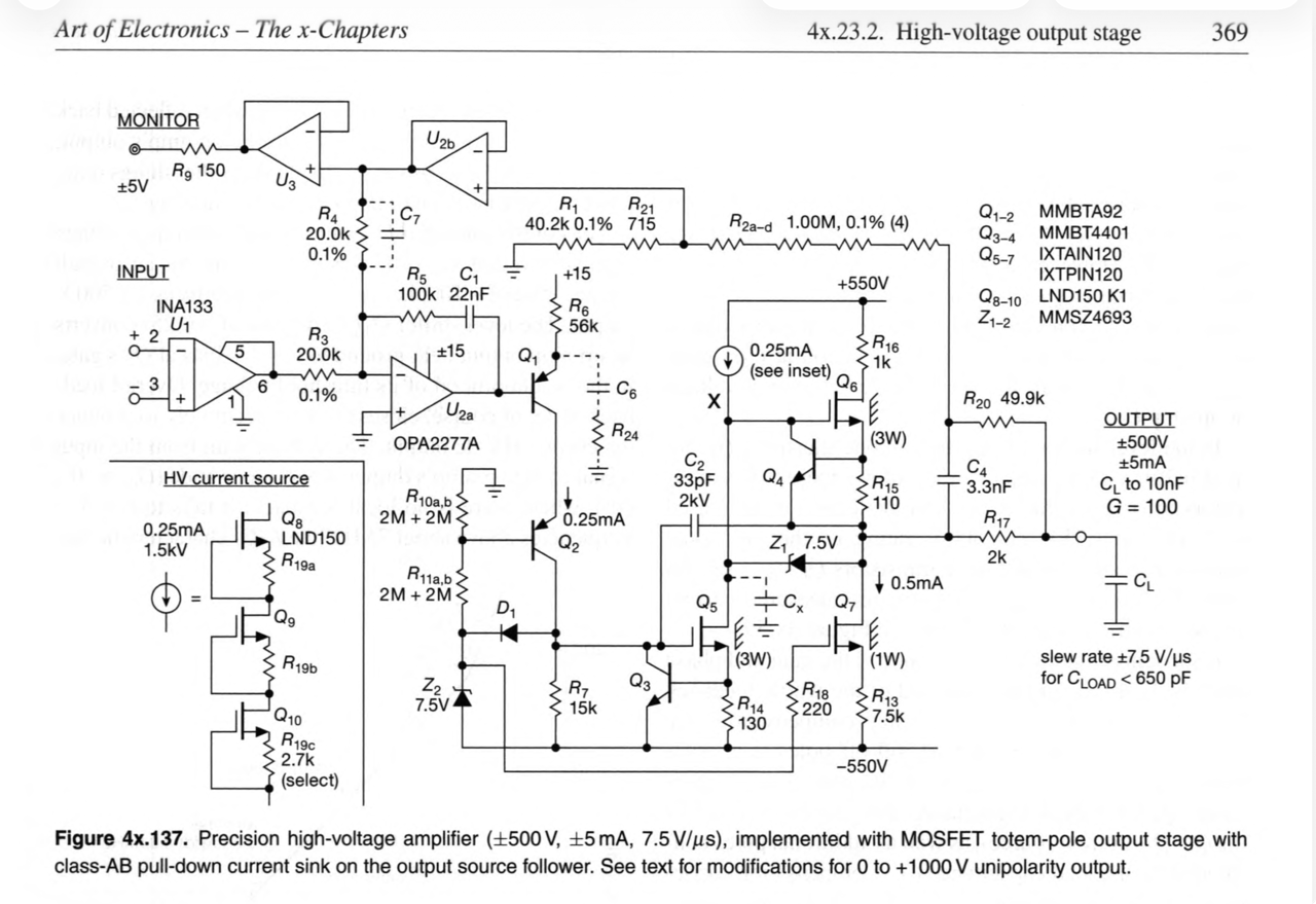
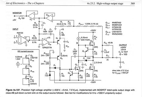
Schaltplan eines Hochspannungs-Ausgangsstufe
650 pF Figure 4x.137. Precision high-voltage amplifier (±500 V, ±5 mA, 7.5 V/µs), implemented with MOSFET totem-pole output stage with class-AB pull-down current sink on the output source follower. See text for modifications for 0 to +1000 V unipolarity output.
in „High Voltage Amplifier“ · Analoge Elektronik und Schaltungstechnik · · Schaltpläne
-
PDF
lm5026.pdf
clamp reset PWM controller is necessary to limit the voltage stress on the main and active clamp MOSFETs. The relationship between the maximum drain-source voltage of the MOSFETs and the maximum PWM duty cycle is provided by the following equation: VIN Vds(max) = 1 - D(max) (1) The main output (OUT_A
in „.lib datei einbinden“ · Analoge Elektronik und Schaltungstechnik ·
-
PDF
drv8312.pdf
ThreePhasePW MM otorD river Check for Samples: DRV8312, DRV8332 FEATURES Because of the low R of the power MOSFETs DS(on) • High-Efficiency Power Stage (up to 97%) with and intelligent gate drive design, the efficiency of these motor drivers can be up to 97%, which enables Low R DS(on)MOSFETs (80 mΩ at T = 25°
in „Versorgung von BLDC für Logic“ · Analoge Elektronik und Schaltungstechnik ·
-
PDF
drv8432-1.pdf
High-Efficiency Power Stage (up to 97%) with PVDD. The DRV8412/32 can operate at up to 500- Low R DS(on)MOSFETs (110 mΩ at T = 25°CJ kHz switching frequency while still maintain precise • Operating Supply Voltage up to 52 V control and high efficiency. They also have an • DRV8412 (power pad down): up to 2 x
in „Schrittmotor - PWM interface?“ · Mikrocontroller und Digitale Elektronik ·
-
PDF
Infineon-Evaluation_Board_EVAL-1EDx20H12AH-SIC-ApplicationNotes-v01_00-EN.pdf
1EDC20H12AH with CoolSiC MOSFETIMZ120R045M1 1EDI20H12AH, 1EDC20H12AH IMZ120R045M1 EiceDRIVER, SiC MOSFET About this document Scope and purpose Thegatedriverevaluation boardsEVAL-1EDC20H12AH-SICand EVAL-1EDI20H12AH-SICwiththe EiceDRIVER ™ 1EDC20H12AH or 1EDI20H12AHandCoolSiC MOSFETIZM120R045M1weredevelopedtodemonstrate
in „H-Brücke funktioniert nur mit Tastkopf“ · Mikrocontroller und Digitale Elektronik ·
-
 Bild
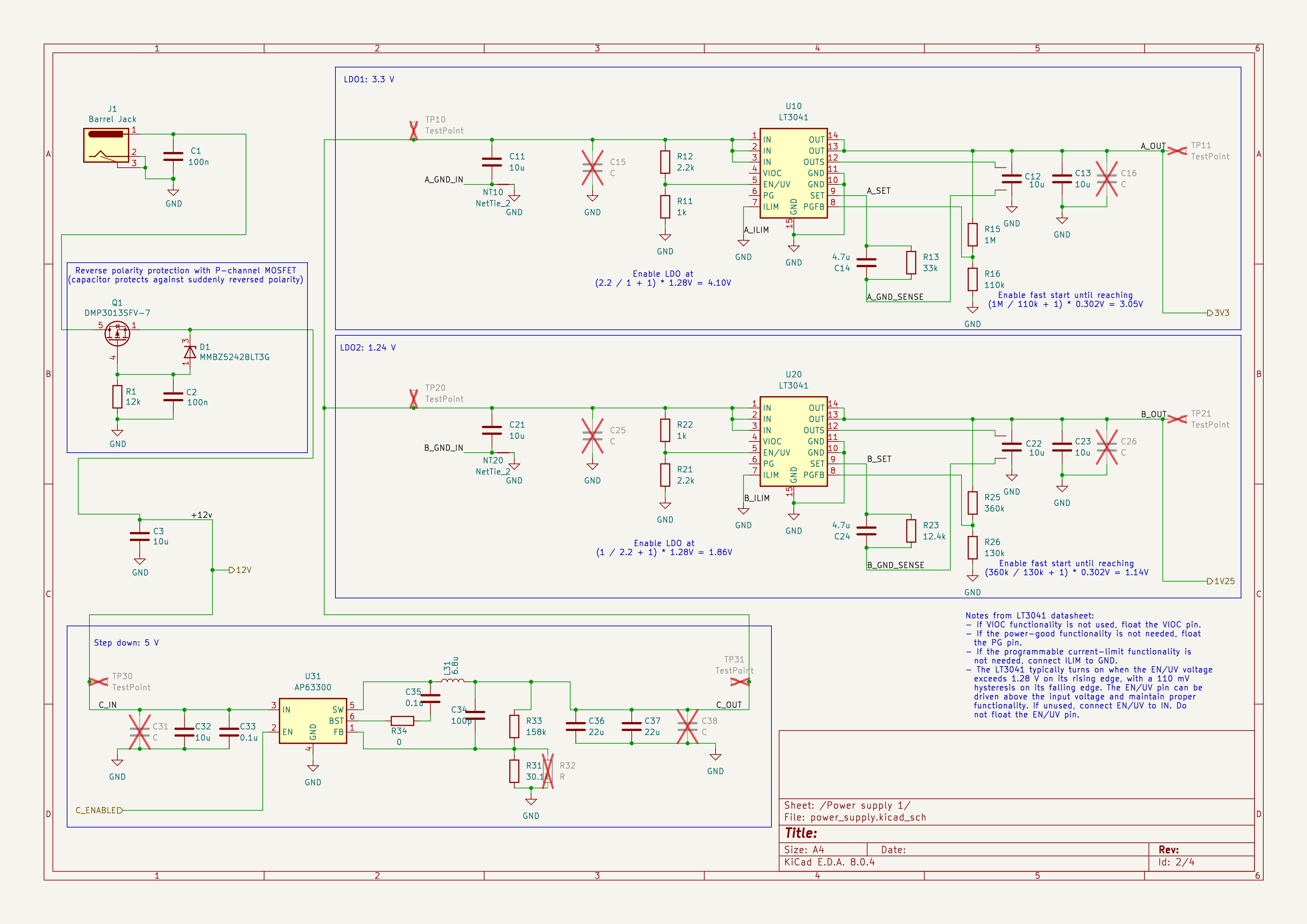
Schaltplan eines Netzteils
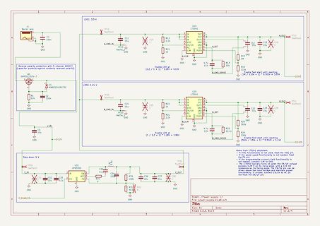
J1 Barrel Jack, C1 100n, GND, Reverse polarity protection with P-channel MOSFET, Capacitor protects against suddenly reversed polarity, Q1 DPM3015V-7, D1 MBB5242BLT3G, R1 12k, C2 100n, LD01: 3.3V, A_GND_IN, TP10 TestPoint, C11 10u, C15, R12 2.2k, U10 LT3041, IN, EN/UV, VS, PG,
in „Hilfe bei Spannungsversorgung für DVB-S2-NIM“ · Analoge Elektronik und Schaltungstechnik · · Schaltpläne
-
Datei
PL.txt
Antiparallel[] EEMEM = "antyrownol. "; unsigned char InSeries[] EEMEM = "Kolejno A="; unsigned char mosfet[] EEMEM = "-MOS"; unsigned char emode[] EEMEM = "-E"; unsigned char dmode[] EEMEM = "-D"; unsigned char jfet[] EEMEM = "-JFET"; unsigned char Thyristor[] EEMEM = "Tyrystor "; unsigned char Triac[]
-
Datei
sSimmics.txt
sconnectgraph.eps twoportss.eps coplanar.tex mosband.eps sconnectloop.eps vam.eps coplanarzl.eps mosfet.eps sconnectpath.eps vccs.eps coupler.eps mosphysical.eps scr.eps vcvs.eps cpconform.eps mostypes.eps sgp.eps vpm.eps cpgap.eps ms_bend_opt.eps siconnectgraph.eps xcircuit.eps cpline.eps mscomparezl.eps
-
Datei
uSimmics.txt
sconnectgraph.eps twoportss.eps coplanar.tex mosband.eps sconnectloop.eps vam.eps coplanarzl.eps mosfet.eps sconnectpath.eps vccs.eps coupler.eps mosphysical.eps scr.eps vcvs.eps cpconform.eps mostypes.eps sgp.eps vpm.eps cpgap.eps ms_bend_opt.eps siconnectgraph.eps xcircuit.eps cpline.eps mscomparezl.eps
-
PDF
Schaltplan_ohne_Dimmer.pdf
Ansteuerung LED-Streifen und Spiegellampen mit Stellaris-Launchpad N Author Nulldurchgangserkennung MOSFET-Dimmer File Document D:\01_Document ... Schaltplan_ohne_Dimmer.dsn Revision Date Sheets 1.0 22.7.2018 1 of 1
in „Zahnputzspiegel“ · Offtopic ·
-
PDF
KIWI_KP212X.pdf
Regulation (PSR)/QR-Buck CV/CC Power Switch FEATURES GENERAL DESCRIPTION Integrated with 650V MOSFET KP212X is a family of a high performance Primary Support Flyback and Buck Topology: Side Regulation (PSR)power switch with high Flyback PSR Control (SEL= Floating) precision CV/CC control ideal
-
PDF
Blockschaltbild.pdf
ADC Drucksensor Drucksensor Insgesamt 8 redundante Zellen. (dargestellt: 4) Digital Outputs : 8 (Mosfet Driver) Analog Inputs : 8 (Spannung an der Zelle) I²C-Bus : 1 1x 400kHz (DC/DCWandler & ADCs) I²C DC/DC NMOS Shunt Terminal Zelle Alarm (DO) (AO) Driver Amplifier (AO) To (DI) I²C Micro- Controller
in „uC from Scratch“ · Mikrocontroller und Digitale Elektronik ·
-
PDF
MAX8211-MAX8212.pdf
voltage, since the __________Applications Information comparator input (THRESH pin) is a low-leakage MOSFET transistor. This further reduces system current Basic Voltage Detectors drain. The tolerance of the internal reference has also Figure 3 shows the basic circuit for both undervoltage been significantly
in „low batt anzeige“ · Analoge Elektronik und Schaltungstechnik ·
-
PDF
irs2453d.pdf
begin to oscillate. Normal Operating Mode Once V CC reaches the start-up threshold V CCUV+, the MOSFET M1 opens, RT increases to approximately V CC (VCCV RT+ and the external CT capacitor starts charging. Once the CT voltage reaches V CT- (about 1/3 of VCC, established by an internal resistor ladder
in „oscillator, 555, gate driver“ · Mikrocontroller und Digitale Elektronik ·
-
Datei
Bosch_Athlet_DIY_240619.ino
0, 0, 0, 0, HOST=1, SHDN=0 ->switch to host-mode I2C_8Bit_writeToModule(0x10, 1, 0b00000110); //MOSFETs CHG=1, DSG=1 ->manually switch on mosfets again //measure current for charge and brush analogReference(DEFAULT); // Vref=3.3 V delay(20); //stabilize voltages Serial.println("----- start of cyclic
in „Bosch Athlet 25,2 V Akku 7 Stück Tauschen“ · Analoge Elektronik und Schaltungstechnik ·
-
Datei
Athlet_V1_4_32_4.ino
0, 0, 0, 0, HOST=1, SHDN=0 ->switch to host-mode I2C_8Bit_writeToModule(0x10, 1, 0b00000110); //MOSFETs CHG=1, DSG=1 ->manually switch on mosfets again //measure current for charge and brush analogReference(DEFAULT); // Vref=3.3 V delay(20); //stabilize voltages Serial.println("----- start of cyclic
in „Bosch Athlet 25,2 V Akku 7 Stück Tauschen“ · Analoge Elektronik und Schaltungstechnik ·
-
PDF
sct2080ke.pdf
SCT2080KE N-channel SiC power MOSFET Datasheet Outline V 1200V TO-247 DSS R (Typ.) 80m DS(on) I 40A D P 262W D Features Inner circuit 1) Low on-resistance (2) 2) Fast switching speed (1) Gate (2) Drain 3) Fast reverse recovery *1
in „Verarmungs- oder Anreicherungstyp“ · Analoge Elektronik und Schaltungstechnik ·
-
PDF
AL5802-DIO.pdf
the I EN pin (3) with an external open-collector NPN transistor or open- 1 2 3 E drain N-channel MOSFET. C The AL5802 is available in a SOT26 package and is ideal for driving SOT26 N 20mA to 120mA LED currents. A V D Features Applications A Reference voltage VRSET = 0.65V Linear LED driver -40
in „Dimensionierung von LED-Dimm-Schaltung“ · Analoge Elektronik und Schaltungstechnik ·
-
PDF
NTD4963N-D.PDF
NTD4963N Power MOSFET 30 V, 44 A, Single N−Channel, DPAK/IPAK Features • Low R to Minimize Conduction Losses DS(on) • Low Capacitance to Minimize Driver Losses http://onsemi.com • Optimized Gate Charge to Minimize Switching
in „Vergleichsmosfet NTD 4963N“ · Analoge Elektronik und Schaltungstechnik ·
-
PDF
pnFET_Si1551.pdf
_._-------_. _ .._-_ _._ _ --_ ..__ - - - - - Si1551DL Vishay Siliconix Complementary 20 V (D-S) MOSFET PRODUCT SUMMARY FEATURES • Halogen-free According to IEC 61249-2-21 V DS (V) R DS(on)(Ω) D (A) Q gTyp.) 1.9 at V = 4.5 V 0.30 Definition GS TrenchFET Power MOSFET: 2.5 V Rated N-Channel 20 3.7 at GS
in „Kann diese Schaltung den 74HC132 killen?“ · Analoge Elektronik und Schaltungstechnik ·
-
PDF
pnFET_Si1551.pdf
_._-------_. _ .._-_ _._ _ --_ ..__ - - - - - Si1551DL Vishay Siliconix Complementary 20 V (D-S) MOSFET PRODUCT SUMMARY FEATURES • Halogen-free According to IEC 61249-2-21 V DS (V) R DS(on)(Ω) D (A) Q gTyp.) 1.9 at V = 4.5 V 0.30 Definition GS TrenchFET Power MOSFET: 2.5 V Rated N-Channel 20 3.7 at GS
in „Warum sperrt P-Kannal FET M1 nicht“ · Analoge Elektronik und Schaltungstechnik ·
-
PDF
PAM8302A.pdf
V N A-Weighting — 120 200 µV Oscillator Frequency OSC — 200 250 300 kHz Drain-Source On-State P MOSFET — 0.45 0.50 Ω Resistance RDS(ON) DS = 100mA N MOSFET — 0.20 0.25 SHD Input High V — 1.2 — — SH V SHD Input Low VSL — — — 0.4 Over Temperature Protection OTP Junction Temperature +120 +135 — °C Over
in „PAM8302A Dimensionierung Ci und R“ · Mikrocontroller und Digitale Elektronik ·
-
PDF
si1551dl.pdf
Si1551DL Vishay Siliconix Complementary 20 V (D-S) MOSFET PRODUCT SUMMARY FEATURES • Halogen-free According to IEC 61249-2-21 V DS (V) R DS(on)(Ω) D (A) Q gTyp.) 1.9 at V = 4.5 V 0.30 Definition GS TrenchFET Power MOSFET: 2.5 V Rated N-Channel 20 3.7 at GS
in „CMOS: NAND bauen?“ · Mikrocontroller und Digitale Elektronik ·
-
PDF
mp1482.pdf
minimize the loop area formed by input cap, and 4) Route SW away from seFsitive analog high-side MOSFET and low-side MOSFET. 5) Connect IN, SW, and especially GND the chip to improve thermal performancecool C5nd long-term reliability. 4.75V to 18V D S 6 R4 IN BS1 N L1 N 7 8 EN MP1482 E SW 5 G R1 OUTPUT
in „Empfehlung Step Down Converter IC“ · Analoge Elektronik und Schaltungstechnik ·
-
PDF
drv8711.pdf
controller • Pulse Width Modulation (PWM) Microstepping Motor Driver that uses external N-channel MOSFETs to drive a – Built-In 1/256-Step Microstepping Indexer bipolar stepper motor or two brushed DC motors. A microstepping indexer is integrated, which is capable – Drives External N-Channel MOSFETs of
in „UV-Laserdrucker II“ · Platinen ·
-
Datei
ADC_2.txt
abschaltung cpi AKKU_L,low(W_LAGERUNG) ldi A,high(W_LAGERUNG) cpc AKKU_H,A brcc adc_akku_1 sbrs P_FLAGS,MOSFET rjmp abschaltung adc_akku_1: tst INTERVALLZEIT brne adc_akku_end cpi AKKU_L,low(W_FREISCHWELLE) ldi A,high(W_FREISCHWELLE) cpc AKKU_H,A brcs abschaltung tst RUHEZEIT brne flimmern cpi AKKU_L,low(W_
in „Wie programmiert man eine Hysterese in Assembler ?“ · Mikrocontroller und Digitale Elektronik ·
-
PDF
irl540npbf.pdf
PD - 94997 IRL540NPbF HEXFET Power MOSFET Lead-Free www.irf.com 1 2/10/04 IRL540NPbF 2 www.irf.com IRL540NPbF www.irf.com 3 IRL540NPbF 4 www.irf.com IRL540NPbF www.irf.com 5 IRL540NPbF 6 www.irf.com IRL540NPbF www.irf.com 7 IRL540NPbF TO-220AB
in „N-Channel Mosfet max. Spannung Gate zu Drain“ · Mechanik, Gehäuse, Werkzeug ·
-
PDF
MT777XL.PDF
OVP pin MT777XL integrates Rectifier Bridge, • Thermal regulation function freewheeling diode and MOSFET. With MAXIC • Available in ASOP7 package proprietary internal high-voltage power supply solution, no external VCC capacitor and startup TYPICAL APPLICATION CIRCUIT resistor are needed, which achieves
in „MT7771 led driver, wie strom einstellen?“ · Haus & Smart Home ·
-
PDF
ttester.pdf
. . . . . . . . . . . . . . . . . . . 64 5.1.1 Messung eines PNP-Transistors oder eines P-Kanal MOSFETs . . . . . . . . . 65 5.1.2 Messung eines NPN-Transistors oder eines N-Kanal-MOSFET . . . . . . . . . 66 5.1.3 Vereinfachter Ablauf der Transistorerkennung . . . . . . . . . . . . . . . . . . 69 5.1.4
-
Datei
Bauteilliste3.txt
25Stk. BD442 Trans.PNP 4A/80V 0,10.- 50Stk. BDX34C Trans. Darl.PNP 10A/100V 0,10.- 250Stk. BUZ74 Mosfet N TO220 500V/2A/4Ohm 0,10.- 1000Stk.BC546 Trans.NPN TO92 65V/100mA 0,02.- 8Stk. 80C535 MC Siemens 8Bit inkl.68pol.THT Fassung 1,50.- 9Stk. 80535 MC Siemens 8Bit inkl.68pol.THT Fassung 1,50.- 200Stk
in „[V] Bauteile THT“ · Markt ·
-
Datei
Bauteilliste4.txt
25Stk. BD442 Trans.PNP 4A/80V 0,10.- 50Stk. BDX34C Trans. Darl.PNP 10A/100V 0,10.- 250Stk. BUZ74 Mosfet N TO220 500V/2A/4Ohm 0,10.- 200Stk. BC546 Trans.NPN TO92 65V/100mA 0,02.- 9Stk. 80535 MC Siemens 8Bit inkl.68pol.THT Fassung 1,50.- 200Stk. MC14521 C-MOS 24Stage Div./Osz. DIP16 0.10.- 12Stk. ICM7211AIPL
in „[V] Bauteile THT“ · Markt ·
-
PDF
TP4056.pdf
Programmable Charge Current Up to ·Input Supply Voltage(V ):-0.3V~8V CC 1000mA ·TEMP:-0.3V~10V ·No MOSFET, Sense Resistor or Blocking ·CE:-0.3V~10V Diode Required ·BAT Short-Circuit Duration:Continuous · Complete Linear Charger in SOP-8 ·BAT Pin Current:1200mA Package for Single Cell Lithium-Ion ·PROG
in „Lithium Akku dauerladen“ · Analoge Elektronik und Schaltungstechnik ·
-
Datei
Bauteilliste.txt
300Stk. BD442 Trans.PNP 4A/80V 0,10.- 100Stk. BDX34C Trans. Darl.PNP 10A/100V 0,10.- 300Stk. BUZ74 Mosfet N TO220 500V/2A/4Ohm 0,10.- 1000Stk.BC546 Trans.NPN TO92 65V/100mA 0,02.- 50Stk. ICL7667 MF-Treiber DIP8 0,20.- 8Stk. 80C535 MC Siemens 8Bit inkl.68pol.Fassung 1,50.- 9Stk. 80535 MC Siemens 8Bit inkl
in „[V] Bauteile THT“ · Markt ·
-
Datei
Bauteilliste2.txt
200Stk. BD442 Trans.PNP 4A/80V 0,10.- 100Stk. BDX34C Trans. Darl.PNP 10A/100V 0,10.- 300Stk. BUZ74 Mosfet N TO220 500V/2A/4Ohm 0,10.- 1000Stk.BC546 Trans.NPN TO92 65V/100mA 0,02.- 50Stk. ICL7667 MF-Treiber DIP8 0,20.- 8Stk. 80C535 MC Siemens 8Bit inkl.68pol.THT Fassung 1,50.- 9Stk. 80535 MC Siemens 8Bit
in „[V] Bauteile THT“ · Markt ·
-
PDF
Praesi_Technik.pdf
Glättungselko 3300 µF S. 23 Platine Festspannungsregler LM7812 Versorgung Arduino und Lüfter S. 24 Platine MOSFET IRF510 Ansteuerung Lüfter S. 25 Platine Anschlüsse für Arduino 12 Versorgung und Peripherie S. 26 Transformator Anschlüsse Primär-wickl ung 6,3mm Flachstecker S. 27 Transformator Anschlüsse Sekundär-wic
in „kleines Punktschweißgerät“ · Mechanik, Gehäuse, Werkzeug ·