-
PDF
edk10_ctt.pdf
your TestApp_Peripheral application project. ♦ Editing the test_ip_selftest.c file to identify the base address for the test_ip core (because the TEST_IP_SelfTest routine requires a base address pointer). To obtain this information, you must refer to the xparameters.h file. (Does this seem confusing?
-
Datei
usart_nrf.c
_RealTimeData(u8 *pBuffer) { switch(pBuffer[1]) { case ANSWER_REQ_A_DAT: // 0x89 UsartNrf_Process_BaseDataPort(pBuffer, 0); break; case ANSWER_REQ_A_EVENT: // 0x88 UsartNrf_Process_BaseEventPort(pBuffer, 0); break; case ANSWER_REQ_B_DAT: // 0x91 UsartNrf_Process_BaseDataPort(pBuffer, 1); break; case
in „Wechselrichter Hoymiles HM-xxxx 2,4 GhZ Nordic Protokoll?“ · Mikrocontroller und Digitale Elektronik ·
-
 Bild
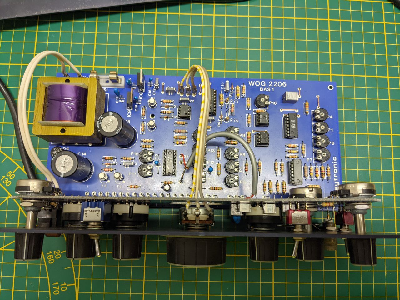
Bestückte Leiterplatte eines Netzteils auf Schneidematte
WOG 2206 BAS 1 C19 C18 C20 R25 CP10 IC91 R24 P9 IC92 P6 P7 P8 P13 P16 P17 T3 C14 T2 C15 C16 C17 C18 C19 C20 C21 C22 C23 C24 C25 C26 C27 C28 C29 C30 C31 C32 C33 C34 C35 C36 C37 C38 C39 C40 C41 C42 C43 C44 C45 C46
in „Tantalkondensatoren am Spannungsregler ersetzen“ · Analoge Elektronik und Schaltungstechnik · · Platinenfotos
-
PDF
LEDs-Segment1.pdf
-1 Rot 181263 - 62 2,20 140 NAT-SSG-HJ-1 Grün 181266 - 62 3,50 150 NAB-FSG-HJ-1 Blau 181267 - 62 3,40 150 LMFLC4500Z-YW Si Gelb-Weiß 182969 - 62 3,50 120 LEDs Betrieb Spannung Total pro Strang Farben Flächen 12 48 12 4 12 Transistor Name Emitter-base voltage V Collector current A Total power dissipation
in „Vorwiderstand & Basiswiderstand“ · Analoge Elektronik und Schaltungstechnik ·
-
PDF
Elektor.pdf
R2 C3 C5 0 k nent numbers correspond to the 6 1 47µ 220µ labels on the circuit boards. In con- R5 40V 40V 11V7 2k2 trast to the usual practice with Elec- R R3 R12 R13 * 0 8V5 0 2 tor projects, the components are not 1 2 numbered sequentially for the com- M M plete circuit, but instead separately for
in „Röhrenverstärkerstufe ECC XX welches System zuerst?“ · Analoge Elektronik und Schaltungstechnik ·
-
PDF
191095-an-01-de-ROBONOVA-I_BAUSATZ.pdf
...................................................................................................40 Nutzung der Motion Feedback Funktionen..................................................40 Manuelle Einstellung der Servopositionen:..................................................41 Einstellung der
in „Tubularer Linearmotor“ · Offtopic ·
-
PDF
RDA5851S.pdf
be configured in each corresponding module's registers), then they are filtered by the System or Base Band IRQ Controller (the mask is set in System IRQ Control or Base Band IRQ Control registers). The interrupts must be cleared in the corresponding module. For power saving, one CPU can shut down its
-
Datei
httpd.c
pgmspace.h> #include <stdio.h> #include <stdlib.h> #include <string.h> #include "stack.h" #include "base64.h" #include "analog.h" #include "wol.h" #include "timer.h" #include "usart.h" #if USE_CAM #include "camera/cam.h" #endif //USE_CAM #include "httpd.h" #include "webpage.h" #include "lcd.h" #include
in „AVR Net IO Dropdown Liste“ · Mikrocontroller und Digitale Elektronik ·
-
PDF
STEPPII_55_56_LT_hardware_manual_ver_1.01.pdf
HOLES ) .............................................................................................. 40 7.6.1.1 Mounting the cradle to the terminal ..............................................................................................40 7.6.1.2 Placing the terminal .............................
in „Frage an die GPS- ( Ortungsspezialisten)“ · Mikrocontroller und Digitale Elektronik ·
-
PDF
heds-1300.pdf
Ratings @ T = 25 A °C Parameter Symbol HEDS- Min. Max. Units Fig. Notes Storage Temperature Ts 1200 -40 +75 °C 1300 -40 +75 °C Operating Temperature TA 1200 -20 +70 °C 1300 -20 +70 °C Lead Soldering Temperature 1200 260°C 1 1.6 mm from Seating Plane 1300 for 10 sec. 1 Average LED Forward If 1200 10 40 mA 3 Current 1300 50 mA 2 Peak LED Forward Current Ifpk 1200 40 mA 7 4 1300 75 mA 7 4 Reverse LED Input Voltage Vr 1200 2.5 V 1300 5.0 V Photodiode Bias Vd 1200 -0.3 20 V 5 (Id = 100 A max) 1300 -0.3 20 V 5 Notes: 1. Caution: The thermal constraints of the acrylic
in „Kugelschreiber mit Barcodescanner bei Pollin“ · Mikrocontroller und Digitale Elektronik ·
-
PDF
MRF150.pdf
Class AB) MRF150 MOTOROLA RF DEVICE DATA 2 25 250 200 ) H 20 T 150 VDD =50V M A 100 5 B ( 1 ( R 50 40V IDQ=250mA I15 E A VDD =50V O 00 10 20 30 G I =250mA P E DQ U W10 Pout=150W(PEP) T 250 P U 200 , z u150 VDD =50V M 5 Po100 0 3 50 40 I =250mA V DQ 0 0 2 5 10 20 50 100 200 0 1 2 3 4 5 6 f,FREQUENCY(MHz
in „Wärmeleitpad gesucht für POWER FET MRF150“ · Analoge Elektronik und Schaltungstechnik ·
-
PDF
TDA1558.pdf
Vno noise output voltage RS= 0 − 150 − V |I| input impedance 50 − − k Gv closed loop voltage gain 39 40 41 dB ORDERING INFORMATION EXTENDED TYPE PACKAGE NUMBER PINS PIN POSITION MATERIAL CODE TDA1558Q 17 DIL plastic SOT243R (1) Note 1. SOT243-1; 1996 August 21. May 1992 2 Philips Semiconductors Product
in „TDA1558 Verstärker“ · Analoge Elektronik und Schaltungstechnik ·
-
Datei
gpu_caps_viewer_report_win7.txt
===================================[ System / CPU ] - CPU Name: Intel(R) Core(TM) i7-3770 CPU @ 3.40GHz - CPU Core Speed: 3392 MHz - CPU logical cores: 8 - Family: 6 - Model: 10 - Stepping: 9 - Physical Memory Size: 16384 MB - Operating System: Windows 7 64-bit build 7601 [Service Pack 1] - PhysX Version
in „Horizon EDA [War: Neues, halbfertiges Elektronik-CAD-Programm]“ · Projekte & Code ·
-
PDF
irl7486mpbf-936689.pdf
4.5V, D = 62A V GS(th) Gate Threshold Voltage 1.0 1.8 2.5 V VDS = VGS ID= 150µA ––– ––– 1.0 VDS = 40V, VGS= 0V IDSS Drain-to-Source Leakage Current ––– ––– 150 µA VDS = 40V, VGS= 0V, TJ= 125°C IGSS Gate-to-Source Forward Leakage ––– ––– 100 VGS = 20V Gate-to-Source Reverse Leakage ––– ––– -100 nA VGS
in „Reparatur Makita XWT08Z (DTW1002Z)“ · Analoge Elektronik und Schaltungstechnik ·
-
PDF
TLV431-DIO.pdf
mV (-40°C to +85°C) 11mV (-40°C to +125°C) ‡ • 80µA Minimum cathode current N/C 2 • 0.25Ω Typical Output Impedance • Adjustable Output Voltage REF to 18V CATHODE 3 4 REF • Lead-Free Finish; RoHS Compliant
in „Schaltung zur Ürberwachung der 9 Volt Batteriespannung“ · Analoge Elektronik und Schaltungstechnik ·
-
PDF
ST7735S.pdf
.................................................................................................. 40 Figure 11 8080-series parallel bus protocol, read data from register or display RAM.................................... 40 Figure 12 6800-Series Write Protocol .......................................
in „[STM32/HAL] Treiber für ST7735 160 x 80 TFT“ · Projekte & Code ·
-
PDF
sfh610a-1.pdf
FEATURES Dimensions in Inches (mm) • Variety of CurrentTransfer Ratios at I =10 FA 2 1 – SFH610A/617A-1, 40–80% pin one ID – SFH610A/617A-2, 63–125% SFH610A – SFH610A/617A-3, 100–200% .255 (6.48) – SFH610A/617A-4, 160–320% .268 (6.81) Anode 1 4 Emitter • Low CTR Degradation • Good CTR Linearity Depending on
in „Frage zu Optokoppler“ · Mikrocontroller und Digitale Elektronik ·
-
PDF
TEMP_DRUCK.pdf
Sensors. Wird die maximale Auflösung verlangt, so muss die Messung ggf. in mehreren Bereichen mit den Basen B1, B2, ... Bn und den Fensterbreiten F1 = F2 = ... = Fn = 4 erfolgen. Der jeweils gültige Bereich muss in einer Vormessung ermittelt werden. Am einfachsten wählt man dazu B = 0 und F = 16 . Dabei
in „Temperatur - Luftdruckmessung“ · Mikrocontroller und Digitale Elektronik ·
-
Datei
rfm12.inc
ldi YL, 0xd8 ; 433MHz, 12,0pF rcall rfm_com_send ; Power Management ldi YH, 0x82 ; Enable Receiver, BaseBandBlock, Synthesizer, Crys. Oszillator (auch für->), ext. Clock, Wake up ldi YL, 0xd8 ; Disable et, Low Bat rcall rfm_com_send ; Frequenz Setting ldi YH, 0xa6 ldi YL, 0x40 ; 434MHz Mittenfrequenz fo
in „RFM12 Statusabfrage“ · Mikrocontroller und Digitale Elektronik ·
-
PDF
CYStech_MTB06N03H8.pdf
53 Avalanche Energy @ L=0.1mH, I D=53A, R G=25Ω EAS 140 RepetitiveAvalanche Energy @ L=0.05mH EAR 40 *2 mJ TC=25℃ 60 Total Power Dissipation TC=100℃ PD 32 W Operating Junction and Storage Temperature Range Tj, Tstg -55~+175 °C 100% UIS testing in conditioD=15V, L=0.1mH, G=10V, L=40A, Rated D=25V N-CH
in „[S] CYStech MOSFETs“ · Markt ·
-
PDF
MR851-G.pdf
CHARACTERISTICS FIG.4- TYPICAL JUNCTION CAPACITANCE 20 90 10 80 F ) . ( E T 3.0 N 60 E I R C U P C 1.0 A 40 R N A I R T O N 0 F J 20 Tj=25 C U 0.3 O N T Tj=25 C 0 N 0.1 Pulse Width=300 s 1 2 4 6 10 20 40 60 100 T 1% Duty Cycle REVERSE VOLTAGE. (V) N I .03 .01 0.4 0.6 0.8 1.0 1.2 1.4 1.6 1.8 FORWARD VOLTAGE
in „LTspice Diode Kenngrößen verändern (average forward current, breakdown voltage)“ · Analoge Elektronik und Schaltungstechnik ·
-
PDF
HP_MSA-0520.pdf
Notes: 1. Permanent damage may occur if any of these limits are exceeded. 2. TCASE=25°C. 3. Derateat40mW/°CforT C>125°C. 4. The small spot size of this technique results in a higher, though more accurate determination ofjc than do alternate methods. See MEASURE- MENTS section “Thermal Resistance” for
in „[S] RF-Transistor AT-64020 oder einen adäquaten Ersatz“ · Markt ·
-
PDF
LTV817.pdf
125 *1.Isolation Voltage Viso 5 KV rms *2.Soldering Temperature Tsol 260 *1. AC for 1 minute, R.H. = 40 ~ 60% Isolation voltage shall be measured using the following method. (1)Short between anode and cathode on the primary side and between collector, emitter and base on the secondary side. (2)The isolation
in „Vorwiderstand Optokoppler“ · Analoge Elektronik und Schaltungstechnik ·
-
PDF
complex_signals.pdf
frequency demodu- P = (A + B) ⁄ 2 late an RF input to a complex IF frequency or directly to (10) base-band [12][13][14]. N = (A – B) ⁄ 2 3.1 Direct-Conversion Receiver and The direct-conversion receiver is a good choice of architec- A = P + N ture for less demanding, but highly integrated applications (11) [39][40]. A simplified receiver architecture is shown in Fig. 8. B = P – N using both a complex SFG (Fig. 8. (a)) and a real SFG (Fig. 8. This duality, along with some simple trigometric identities, are (c))
in „Komplexe Frequenz“ · Digitale Signalverarbeitung / DSP / Machine Learning ·
-
Datei
ohne_cf.txt
: HPET id: 0x43538301 base: 0xfed00000 [ 0.000000] SMP: Allowing 1 CPUs, 0 hotplug CPUs [ 0.000000] nr_irqs_gsi: 40 [ 0.000000] PM: Registered nosave memory: 000000000009d000 - 000000000009e000 [ 0.000000] PM: Registered nosave
in „Thin client über speedport w701v einrichten“ · PC Hard- und Software ·
-
PDF
EssentialC.pdf
elements in the array with the simple [ ] syntax such as array[1]. This scheme works by combining the base address of the whole array with the index to compute the base address of the desired element in the array. It just requires a little arithmetic. Each element takes up a fixed number of bytes which is
in „C-Syntax / Compiler“ · Mikrocontroller und Digitale Elektronik ·
-
PDF
AN-9010.PDF
Easy to Drive If the VDS rate of increase is large in the high speed To maintain the on−state, a base drive current 1/5th or turn−off state, there is a voltage drop between the base and 1/10th of collector current is required for the the emitter, which causes the BJT to turn on. This is current−controlled device (BJT). Alarger reverse base drive prevented by increasing the doping density of the P− body + current is needed for the high−speed turn−off of the region, which is at the bottom of the N source region, and current−controlled BJT
in „SMD Mosfet mit Z-Diode für induktive Last“ · Analoge Elektronik und Schaltungstechnik ·
-
PDF
L-53GD_LED_gr_n_5mm_20mcd.pdf
Forward Current 25 mA Peak Forward Current [1] 140 mA Reverse Voltage 5 V Operating/Storage Temperature -40°C To +85°C Lead Solder Temperature [2] 260°C For 5 Seconds Notes: 1. 1/10 Duty Cycle, 0.1ms Pulse Width. 2. 2mm below package base. SPECNO:DSAA5618 REV NO: V.3 DATE:JAN/02/2003 PAGE: 2 OF 3 APPROVED
in „LED's ohne vorwiderstand Oo“ · Analoge Elektronik und Schaltungstechnik ·
-
Datei
SendToCom.BAS
'- SendToCom.BAS ------------------------------------------------ >>fst'16<< - ' - Sendet Daten an eine serielle Schnittstelle ' - Bedienung über ein GUI (Fenster) mit Buttons ' - sucht alle verfügbaren ComPorts ' -
in „kleines Windows Programm zum Senden eines Befehles an die serielle Schnittstelle“ · Softwareentwicklung ·
-
PDF
SMBJ5.pdf
62 0.443 9.9 SMBJ33A/CA 0.2 1 33 36.7 38.6 1 53.3 11.8 1.08 69.7 57 0.512 10.0 SMBJ36A/CA 0.2 1 36 40.0 42.1 1 58.1 10.3 1.35 76 52 0.611 10.0 SMBJ40A/CA 0.2 1 40 44.4 46.7 1 64.5 9.7 1.59 84 48 0.728 10.1 SMBJ48A/CA 0.2 1 48 53.3 56.1 1 77.4 8.1 2.28 100 40 1.03 10.3 SMBJ58A/CA 0.2 1 58 64.4 67.8 1
in „Zener Diode gesucht, die bei 4,0V nur 5-10mA zieht und 2-3 Watt "verbrennen" kann“ · Analoge Elektronik und Schaltungstechnik ·
-
PDF
csd18502kcs.pdf
CSD18502KCS www.ti.com SLPS367A –AUGUST 2012–REVISED OCTOBER 2012 40-V,N -C hannelN exFET™Pow erM O SFETs Check for Samples: CSD18502KCS FEATURES PRODUCT SUMMARY • Ultra Low Qg and Qgd TA= 25°C TYPICAL VALUE UNIT • Low Thermal Resistance V Drain to Source Voltage 40 V
in „Netzteil: 2 Mosfets parallel OK?“ · Analoge Elektronik und Schaltungstechnik ·
-
PDF
UM10736.pdf
document is © NXP Semiconductors N.V. 2017. All rights reserved. User manual Rev. 1.2 — 28 December 2017 40 of 765 NXP Semiconductors UM10736 Chapter 3: LPC15xx System configuration (SYSCON) Table 28. Register overview: System configuration (base address 0x4007 4000) …continued Name Access Offset Description
in „LPC1549 USB Virtual COM-Port“ · Mikrocontroller und Digitale Elektronik ·
-
Datei
stm32f10x_rcc.lst
8000000) 124:lib/stm32f10x_rcc.c **** 125:lib/stm32f10x_rcc.c **** /* CIR register byte 2 (Bits[15:8]) base address */ 126:lib/stm32f10x_rcc.c **** #define CIR_BYTE2_ADDRESS ((uint32_t)0x40021009) 127:lib/stm32f10x_rcc.c **** 128:lib/stm32f10x_rcc.c **** /* CIR register byte 3 (Bits[23:16]) base address *
in „Seltsame Initialisierungen und Abstürze.“ · Mikrocontroller und Digitale Elektronik ·
-
PDF
MC34064P-005.pdf
Air Operating Junction Temperature TJ +150 ⋅C Operating Ambient Temperature TA ⋅C MC34064 0 to +70 −40 to +85 MC33064 NCV33064 −40 to +125 Storage Temperature Range Tstg −65 to +150 ⋅C Maximum ratings are those values beyond which device damage can occur. Maximum ratings applied to the device are individual
in „Brownout detector beim MSP430“ · Mikrocontroller und Digitale Elektronik ·
-
PDF
ili9328.pdf
Single Chip Driver ILI9328 240RGBx320 Resolution and 262K color 1 0 VGL 1 1 Normal Display BASEE Base image display enable bit. When BASEE = “0”, no base image is displayed. The ILI9328 drives liquid crystal at non-lit display level or displays only partial images. When BASEE = “1”, the base image is
in „VW-Werbebeilage mit Display (vidipri)“ · Mikrocontroller und Digitale Elektronik ·
-
PDF
ILI9328DS_V0.1.pdf
Single Chip Driver ILI9328 240RGBx320 Resolution and 262K color 1 0 VGL 1 1 Normal Display BASEE Base image display enable bit. When BASEE = “0”, no base image is displayed. The ILI9328 drives liquid crystal at non-lit display level or displays only partial images. When BASEE = “1”, the base image is
in „[V]erkaufe TFT 2.8" und TFT 2.4" mit adapter PCB“ · Markt ·
-
Datei
Code_BT_MOdul.txt
0x01 #define SW_versionMinor 0x01 #define LEDC_CHANNEL_0 0 #define LEDC_TIMER_13_BIT 13 #define LEDC_BASE_FREQ 5000 #define LED_PIN 2 #define Timer_pending_cyclic_maxvalue 1000 #define Timer_timeout_Maxvalue 3000 #define HEXCODE_BIT1_READ_SENSOR_1 0x31 #define HEXCODE_BIT1_READ_SENSOR_2 0x32 #define HEXCODE_BIT1
in „mehrere Zeichen per UART empfangen“ · Mikrocontroller und Digitale Elektronik ·
-
PDF
b82450a_e-1.pdf
Immobilizer – PEPS (Passive Entry, Passive Start) ■ TPMS (Tire Pressure Monitoring Systems) Terminals ■ Base material CuSn6 ■ Layer composition Ni, Sn (lead-free) ■ Electro-plated Marking ■ Marking on component: Manufacturer, L value in nH, letter “E”, date of manufacture (YWWD), last five digits of lot number
in „Schlüsselcodes in EEPROM identifizieren“ · Fahrzeugelektronik ·
-
PDF
Evolutionary_Audio.pdf
especially The inherent snag in this approach is at the extreme ends of the audio spec that the base voltage/collector current trum, by avoiding the need for this characteristics of germanium and sili component have remained one of the contransistors aredifferent, withthat of majorbenefitsof"solid-state
in „Eigenbau Verstärker - Verbesserungen“ · Analoge Elektronik und Schaltungstechnik ·
-
PDF
Evol._Audio_ks_-_WW.pdf
especially The inherent snag in this approach is at the extreme ends of the audio spec that the base voltage/collector current trum, by avoiding the need for this characteristics of germanium and sili component have remained one of the contransistors aredifferent, withthat of majorbenefitsof"solid-state
in „Quasi Komplementär und Komplementäre Transistoren“ · Analoge Elektronik und Schaltungstechnik ·
-
PDF
tm512ac_v1-7_en.pdf
ground. 2. Recommended Working Conditions Unless otherwise specified, VDD=5V when tested at TM512AC -40℃~+65℃. Parameter Paramet Minimum Typical Maxim Unit er Test condition um name symbol value value value Logic supply Vdd -- 3.8 5.5 6 V voltage High level input Vih -- 0.7Vdd -- Vdd V voltage Low level
in „TM512AC - Startadresse programmieren“ · Mikrocontroller und Digitale Elektronik ·
-
PDF
DIODES_INC_BCR420UW6_ENG_TDS.pdf
Typical Electrical Characteristics BCR420U (Cont.) (@A = +25°C, unless otherwise specified.) 3.0m 0.015 -40°C 2.5m OUT 0A R = open 85°C 25°C 2.0m ext 0.010 ) A A 1.5m ( ( T 85°C N O IE 1.0m -40°C 0.005 25°C V =2V 500.0µ OUT R = open ext 0.0 5 10 15 20 25 30 35 40 0.0000 5 10 15 20 25 30 V (V) V (V) EN EN V
in „BCR420W67 zu wenig strom“ · Analoge Elektronik und Schaltungstechnik ·
-
PDF
p75nf75.pdf
STP75NF75FP Package mechanical data TO-220 MECHANICAL DATA DIM. mm. inch MIN. TYP MAX. MIN. TYP. MAX. A 4.40 4.60 0.173 0.181 b 0.61 0.88 0.024 0.034 b1 1.15 1.70 0.045 0.066 c 0.49 0.70 0.019 0.027 D 15.25 15.75 0.60 0.620 E 10 10.40 0.393 0.409 e 2.40 2.70 0.094 0.106 e1 4.95 5.15 0.194 0.202 F 1.23 1.32 0.048 0.052 H1 6.20 6.60 0.244 0.256 J1 2.40 2.72 0.094 0.107 L 13 14 0.511 0.551 L1 3.50 3.93 0.137 0.154 L20 16.40 0.645 L30 28.90 1.137 øP 3.75 3.85 0.147 0.151 Q 2.65 2.95 0.104 0.116 www.DataSheet4U.com 11/16 Package mechanical data STB75NF75
in „Unbekanntes Bauteil im Akkuschrauber“ · Analoge Elektronik und Schaltungstechnik ·
-
PDF
IRLML6401.pdf
rm o - N n i ( a 1.0 r D D 0.5 , ,) -D n VDS = -12V ( D 20μs PULSE WIDTH R 0.0 VGS =-4.5V 0.1 -60 -40 -20 0 20 40 60 80 100 120 140 160 1.0 1.5 2.0 2.5 3.0 3.5 4.0 ° TJ, Junction Temperature ( C) -VGS , Gate-to-Source Voltage (V) Fig 3. Typical Transfer Characteristics Fig 4. Normalized On-Resistance
in „3,3 V schalten mit möglichgst geringem Spannungsabfall“ · Analoge Elektronik und Schaltungstechnik ·
-
PDF
TRC103_Transceiver_RFM_121129.pdf
...................................................................................................40 5.1 DC Electrical Characteristics ..........................................................................................................40 5.2 AC Electrical Characteristics.......................
-
PDF
ST10FlasherDLL.pdf
monitor. M29F400 0x00 Don’t care Monitor29f400 monitor29f400 BR \ F (MHz) 2.5 5 7.5 10 15 20 25 M29F40 0x00 Don’t care Monitor29f40 monitor29f40 9600 Ok Ok Ok Ok Ok Ok Ok Other ST10 Don’t care Don’t care MonitorNoFlash MonitorNoFlash 14400 Ok Ok Ok Ok Ok Ok 19200 Ok Ok Ok Ok Ok Ok Ok 2.1. BSL acknowledge
in „ST10F167 compiler?“ · Mikrocontroller und Digitale Elektronik ·
-
PDF
US-GPL-SG-AA_0117_web.pdf
C/5 Cycle Life Float Life Type Discharge 80% DOD 77°F (25°C) G13EP G16EP CV14.7-15.0 CV13.5-13.8 -40°Fto113°F -40°Fto113°F 400 10years G26EP CC* CC* (-40°Cto45°C) (-40°Cto45°C) (15years) G42EP G13EPX G16EPX CV14.7-15.0 CV13.5-13.8 -40°Fto140°F -40°Fto140°F 400 10years G26EPX CC* CC* (-40°Cto60°C) (-
in „Kaffeemaschine im Gartenhaus“ · Analoge Elektronik und Schaltungstechnik ·
-
PDF
pdftex-a.pdf
\pdfpagesattr . . . . . . . . . . . . . . . . . . . . . . . . . . . . . . . . . . . 40 4.7.2 \pdfpageattr . . . . . . . . . . . . . . . . . . . . . . . . . . . . . . . . . . . . 40 4.7.3 \pdfomitprocset . . . . . . . . . . . . . . . . . . . . . . . . . . . . . . . . . . 40 4.7.4 \pdfpageref
-
PDF
ULQ2003.pdf
Value Unit Output Voltage VO 50 V Input Voltage V I 30 V Collector Current – Continuous IC 500 mA Base Current – Continuous I 25 mA B Operating Ambient Temperature Range T ⋅C A MC1413 –20 to +85 MC1413B –40 to +85 NCV1413B –40 to +125 Storage Temperature Range Tstg –55 to +150 ⋅C Junction Temperature
in „Spannungsabfall über Treiberbaustein“ · Analoge Elektronik und Schaltungstechnik ·