-
PDF
2599932.pdf
0.5-1.4 .020 1217406-1 Flag - 300 Box only 0.51 J .080-.120 .020 Flag - 500 Box only 18-14 0.8-2.0 2.03-3.05 0.51 1217324-1 .250 K .020 1987199-1 [6.35] Bridge Contact 0.51 .150 L .020 [3.81 ] PCB Contact 0.51 1217041-1 .490 [12.45 ] Note: All tab terminals accept stranded, fused stranded or solid lead
in „IDC connector für Kupferlackdraht“ · Mikrocontroller und Digitale Elektronik ·
-
PDF
MHW921.pdf
Pin= 1.0 mW) s1 + b — 220 mA Leakage Current (P = 0 mW; V = 0; V = V = 0) I — 1.0 mA in cont s1 b L Efficiency out = 12.5 W; in= 1.0 mW) (1) f = 890–915 MHz η 35 — % f = 884–890 MHz 33 — Input VSWR (P out= 0.03 to 12.5 W; in= 1.0 mW) (1) VSWR in — 2.0:1 — Harmonics (Pout = 12.5 W; in = 1.0 mW) (1)
in „Gainblock , wie groß wäre die Reichweite ?“ · HF, Funk und Felder ·
-
Datei
LCD_4_45.c
for(i = 0; i < ANZEIGE_STELLEN; i++) zeige_segmente(anzeige[i]); lcd_strobe(); } void long2a(int32_t l, int8_t *s) // Wandelroutine bin -> String { uint32_t tab[] = {1000000000, 100000000, 10000000, 1000000, 100000, 10000, 1000, 100, 10, 1, 0}; uint32_t temp; int8_t i=0,j; if(l) { // wenn l != 0 if(l < 0) { l = -l; *s++ = '-'; // '-' Vorzeichen einfügen } while(tab[i] > l) i++; // Vornullen unterdruecken do { temp = tab[i]; j = '0'; if(temp) { for(;j <= '9'; j++) { l-=temp; if(l < 0) { l += temp; break; }
in „7-Segm. LCD-Ansteuerung, 4-stelliges Einbaumodul, Attiny45“ · Projekte & Code ·
-
Datei
main.c
1; } if (befehl==03) { *se=*se-1; } if(*se==60) *se=00; if(*se==-01) *se=59; lcd_puti2(*se); lcd_gotoxy(8,1); } do { befehl=tasten(); lcd_gotoxy(10,1); lcd_puts(" Set?"); }while(befehl==00); lcd_clrscr(); }while(befehl!
in „Keine Warnung wenn Prog. Speicher voll?“ · Mikrocontroller und Digitale Elektronik ·
-
Datei
main.c
Change_Bank(0x02); ENC28J60_Write_Reg(0x00, 0x0D); ENC28J60_Write_Reg(0x02, 0xF1); ENC28J60_Write_Reg(0x03, 0x40); ENC28J60_Write_Reg(0x0A, 0xEE); ENC28J60_Write_Reg(0x0B, 0x05); ENC28J60_Write_Reg(0x04, 0x15); ENC28J60_Write_Reg(0x06, 0x12); ENC28J60_Change_Bank(0x03); ENC28J60_Write_Reg(0x04, MAC[0]); ENC28J60_Write_Reg(0x05, MAC[1]); ENC28J60_Write_Reg(0x02, MAC[2]); ENC28J60_Write_Reg(0x03, MAC[3]); ENC28J60_Write_Reg(0x00, MAC[4]); ENC28J60_Write_Reg(0x01, MAC[5]); } void main(void) { UART_init(); SPI_init(); ENC28J60_System_Reset(); //ENC28J60_Set_MAC(MAC); ENC28J60_Change_Bank(0x03)
in „ENC28J60 MAC-Adresse setzen nicht richtig möglich“ · Mikrocontroller und Digitale Elektronik ·
-
PDF
GS503__Communication_Protocol__von_http-www.iconcox.com-uploads-soft-140917-1-14091GT538.pdf_.pdf
- 18 - www.iconcox.com 4.5.10 LBS Extended Information Package (0X18) Content LBS Information M M L M M N N N N N N N N N N N N N N N N N N T C N A CI R L CI R L CI R L CI R L CI R L CI R L CI R A Reserve Format Date C C C S A 1 S A 2 S A 3 S A 4 S A 5 S A 6 S d extend Time bit S C SI C S C S C SI
-
Datei
Assembler.s
ldi XL,(1 << OBJ_SRAM) or (1 << OBJ_STMP) ; 0b00000011 0x03 3 ldi XH,(1 << OBJ_CRAM) ; 0b00001000 0x08 8 rcall _StringNewAdd ldi XL,(1 << OBJ_SRAM) or (1 << OBJ_STMP) ; 0b00000011 0x03 3 ldi XH,(1 << OBJ_SRAM) or (1 << OBJ_STMP) ; 0b00000011 0x03 3 rcall _StringNewAdd
in „ISR macht Newbie fertig :P“ · Mikrocontroller und Digitale Elektronik ·
-
PDF
ad620.pdf
in packaging that is smaller than discrete designs, and offers lower amp per channel. 30,000 10,000 L C25,000 3 OP-AMP S 1,000 L IN-AMP E TYPICAL STANDARD F20,000 (3 OP-07s) I p BIPOLAR INPUT O N V 100 IN-AMP M E – P15,000 A z R L 1 O AD620A V 1 10 R10,000 T ( G = 100 L RG R AD620 SUPERßETA T 5,000 1
in „Verständnisproblem Beschaltung Instrumentenverstärker“ · Analoge Elektronik und Schaltungstechnik ·
-
PDF
74HC_HCT74.pdf
reset; positive edge-trigger 6. Functional description Table 3. Function table H = HIGH voltage level; L = LOW voltage level; X = don’t care. Input Output nSD nRD nCP nD nQ nQ L H X X H L H L X X L H L L X X H H Table 4. Function table H = HIGH voltage level; L = LOW voltage level; X = don’t care; ↑ = LOW-to-HIGH
-
Datei
test.c
LCD_PORT; // Status lesen LCD_CE = 1; // Chip Enable High LCD_RD = 1; // Read High LCD_STATUS &= (0x03); // Bits ausmaskieren } void lcd_status_am(void) { pd2 = 0x00; // Port 2 als Eingang LCD_CD = 1; // Commando High LCD_RD = 0; // Read Low LCD_CE = 0; // Chip Enable Low asm ("NOP"); asm ("NOP"); asm
in „C-Programmierung“ · Mikrocontroller und Digitale Elektronik ·
-
Datei
diff-20100823.txt
-Bb -up freq_meter/cpu_mhz.h freq_meter-20100823/cpu_mhz.h --- freq_meter/cpu_mhz.h 2010-08-22 17:03:09.000000000 +0200 +++ freq_meter-20100823/cpu_mhz.h 2010-08-23 22:07:54.000000000 +0200 @@ -1,6 +1,6 @@ -// autogenerated by ./avr_isp.pl, Sun Aug 22 17:03:09 2010 +// autogenerated by ./avr_isp.pl,
in „Reziproker Frequenzzähler+ Optimierte 64bit uint Routinen“ · Projekte & Code ·
-
Datei
Leistungsmesser2.bas
Max_leistung = Leistung End If Return ' ------------------------------ Onoverflow: Incr Wcounthi 'lCount=lCount+65536 Return ' ------------------------------ Sub Do1clock Waitus 2 Pe_clock = 1 Waitus 4 Pe_clock = 0 Waitus 2 End Sub Sub Lcd_write_nibble(byval D As Byte ) Pe_clock = 0 Pe_data = 0 'Clear
in „Interrupts mit BASCOM, Counter“ · Mikrocontroller und Digitale Elektronik ·
-
PDF
DEP128064D-W.pdf
the 8080 series MPU, and the data bus is in an output status when this 17 RDB signal is “L”. When connected to a 6800 series MPU , this is active HIGH. This is used as an enable clock input of the 6800 series MPU. When RD = “H”: Enable. When RD = “L”: Disable. 18 D0 This is an 8-bit bi-directional
in „SH1106 Init-Sequenz“ · Mikrocontroller und Digitale Elektronik ·
-
PDF
Waermemanagement_bei_Leiterplatten.pdf
thermische Widerstand der Lötfläche: ken könnte, wird vermieden. Gleichung 3 d K R thP) = = 118 Thermovia l · A W Lötfläche d (Kupfer) = 280 µm, l (Kupfer) = 360 W/mK; d (FR4) = 370 µm, l (FR4) = 0,30 W/mK; A (Lötfläche) = 10,50 mm². Bei dem maxon compact drive beträgt der thermische Widerstand der Lötfläche
in „Einfluss von thermischen Vias auf den Wärmetransport eines MOSFETs“ · Platinen ·
-
Datei
main.c
Default powerup registers recommended by PCM1774 at page 13/49 /* pcm1774_sendByte(0x40, 0x27); // L-Channel analog output volume pcm1774_sendByte(0x41, 0x27); // R-Channel analog output volume pcm1774_sendByte(0x44, 0x27); // L-Channel digital output volume pcm1774_sendByte(0x45, 0x27); // R-Channel
in „Probleme mit PCM1774 I2S DAC“ · Mikrocontroller und Digitale Elektronik ·
-
Datei
Font2.c
0x00, 0x00, 0x00, 0x00, // Code for char 0x00, 0x00, 0x06, 0x5F, 0x06, // Code for char ! 0x07, 0x03, 0x00, 0x07, 0x03, // Code for char " 0x24, 0x7E, 0x24, 0x7E, 0x24, // Code for char # 0x00, 0x24, 0x2B, 0x6A, 0x12, // Code for char $ 0x63, 0x13, 0x08, 0x64, 0x63, // Code for char % 0x36, 0x49, 0x56, 0x20, 0x50, // Code for char & 0x00, 0x00, 0x00, 0x07, 0x03, // Code for char ' 0x00, 0x00, 0x00, 0x3E, 0x41, // Code for char ( 0x00, 0x00, 0x00, 0x41, 0x3E, // Code for char ) 0x08, 0x3E, 0x1C, 0x3E, 0x08, // Code for char * 0x08, 0x08, 0x3E, 0x08, 0x08, //
in „Mini-Farbdisplay (+mehr) für 1 Euro“ · Mikrocontroller und Digitale Elektronik ·
-
Datei
font6x8.h
0x00, 0x00, 0x00, 0x00, 0x00, // "(space)" 0x00, 0x00, 0x06, 0x5F, 0x06, 0x00, // "!" 0x00, 0x07, 0x03, 0x00, 0x07, 0x03, // """ 0x00, 0x24, 0x7E, 0x24, 0x7E, 0x24, // "#" 0x00, 0x24, 0x2B, 0x6A, 0x12, 0x00, // "$" 0x00, 0x63, 0x13, 0x08, 0x64, 0x63, // "%" 0x00, 0x36, 0x49, 0x56, 0x20, 0x50, // "&" 0x00, 0x00, 0x07, 0x03, 0x00, 0x00, // "'" 0x00, 0x00, 0x3E, 0x41, 0x00, 0x00, // "(" 0x00, 0x00, 0x41, 0x3E, 0x00, 0x00, // ")" 0x00, 0x08, 0x3E, 0x1C, 0x3E, 0x08, // "*" 0x00, 0x08, 0x08, 0x3E, 0x08, 0x08, // "+" 0x00, 0x00
in „Displaytech 64128A an ATMega8“ · Mikrocontroller und Digitale Elektronik ·
-
Datei
font6x8.h
0x00, 0x00, 0x00, 0x00, 0x00, // "(space)" 0x00, 0x00, 0x06, 0x5F, 0x06, 0x00, // "!" 0x00, 0x07, 0x03, 0x00, 0x07, 0x03, // """ 0x00, 0x24, 0x7E, 0x24, 0x7E, 0x24, // "#" 0x00, 0x24, 0x2B, 0x6A, 0x12, 0x00, // "$" 0x00, 0x63, 0x13, 0x08, 0x64, 0x63, // "%" 0x00, 0x36, 0x49, 0x56, 0x20, 0x50, // "&" 0x00, 0x00, 0x07, 0x03, 0x00, 0x00, // "'" 0x00, 0x00, 0x3E, 0x41, 0x00, 0x00, // "(" 0x00, 0x00, 0x41, 0x3E, 0x00, 0x00, // ")" 0x00, 0x08, 0x3E, 0x1C, 0x3E, 0x08, // "*" 0x00, 0x08, 0x08, 0x3E, 0x08, 0x08, // "+" 0x00, 0x00
in „STM32 C was passiert da?“ · Mikrocontroller und Digitale Elektronik ·
-
Datei
uart.c
/* * UART_Test2.c * * Created: 03.03.2016 20:36:39 * Author : SicKn3ss */ #include <avr/io.h> #include <avr/delay.h> void USART_Init( unsigned int baud ) { /* Set baud rate */ UBRR0H = (unsigned char)(baud>>8); UBRR0L = (unsigned char
in „[ATMega644P] UART sendet nichts“ · Mikrocontroller und Digitale Elektronik ·
-
 Bild
Screenshot eines Forenbeitrags über ein Netzteil-Modell
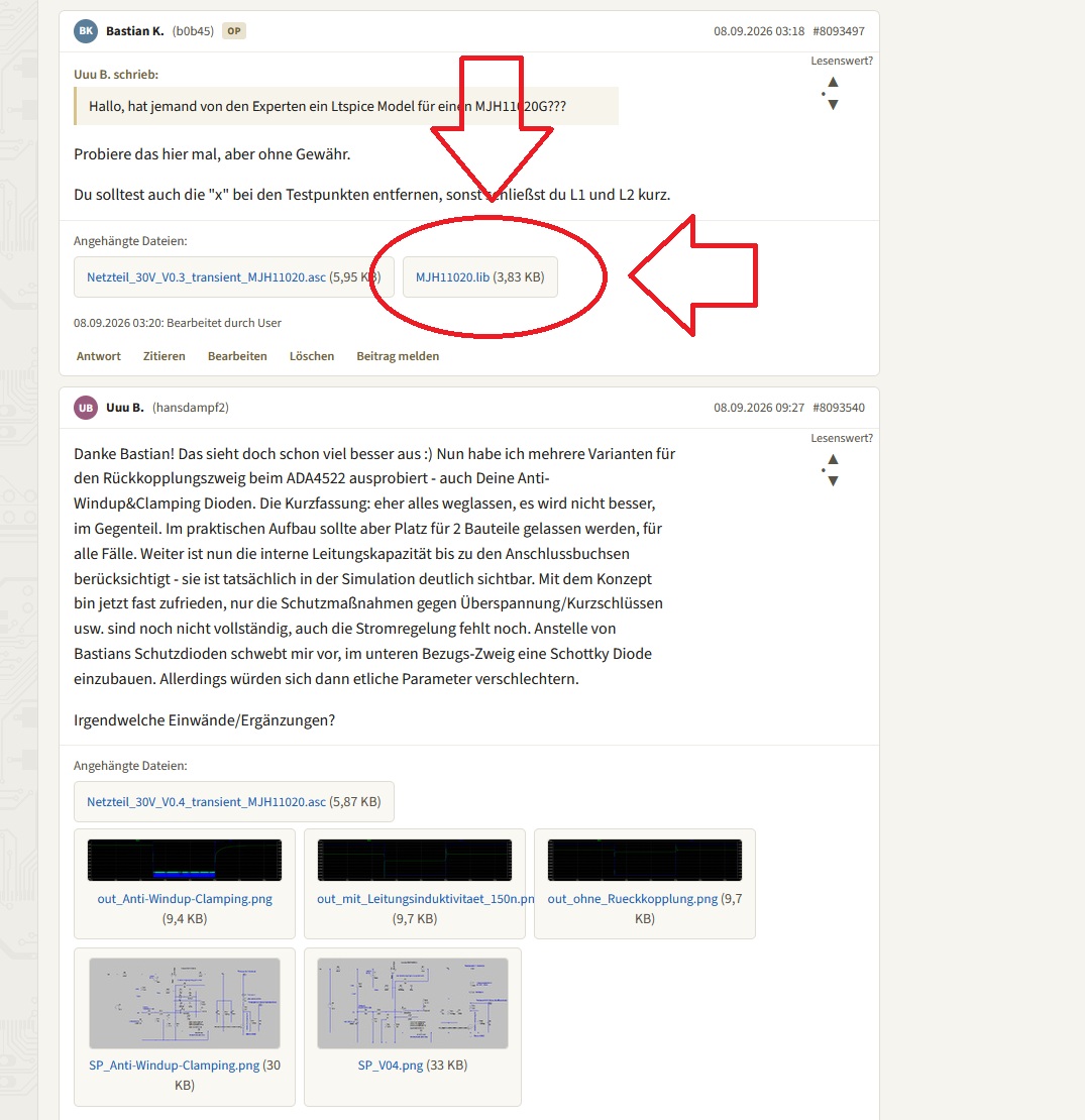
Bastian K. (b0b45) OP 08.09.2026 03:18 #8093497 Uuu B. schrieb: Hallo, hat jemand von den Experten ein Ltspice Model für ein MJH1020G??? Probiere das hier mal, aber ohne Gewähr. Du solltest auch die "x" bei den Testpunkten entfernen, sonst schließt du L1 und L2 kurz. Angehängte Dateien: Netzteil_30V_V0.3_transient_MJH1020.asc (5,95 KB) MJH1020.lib (3,83 KB) 08.09.2026 03:20: Bearbeitet durch User Antwort Zitieren Bearbeiten Löschen Beitrag melden Uuu
in „Nebenprojekt: Analoges Labornetzteil inkl. Schaltplan und Messungen“ · Projekte & Code · · Screenshots
-
PDF
TPSchalter_KM_G_020322.pdf
arbeitet. Tabelle 2 zeigt die über DIP-Schalter einstellbaren Möglich- 1 1 1 1 1 1 1 1 1 D00 D01 D02 D03 P0 keiten. 9-Bit-Header D10 D11 D12 D13 P1 Im normalen Betriebs-Mode wird jeder 8-Bit kundenspezifische Informa- akzeptierte Transponder durch ein kurzes tion (D 00 bis D 03 sowie D 10 bis D20 D21 D22
in „Transponder Lesegerät SUCHE LÖSUNG ???“ · Mikrocontroller und Digitale Elektronik ·
-
PDF
p6smb6.pdf
overshoot. Proper circuit layout, VinTRANSIENT) OVERSHOOT DUE TO V V inRANSIENT) V INDUCTIVE EFFECTS V L VL Vin td t = TIME DELAY DUE TO CAPACITIVE EFFECT D t t Figure 5. Figure 6. 1 0.7 0.5 O 0.3 T 0.2 A PULSE WIDTH F 10 ms N 0.1 T 0.07 R 0.05 E 1 ms D 0.03 0.02 100 ms 10 ms 0.01 0.1 0.2 0.5 1 2 5 10 20
in „was ist das für ein Bauteil“ · Analoge Elektronik und Schaltungstechnik ·
-
PDF
p6smb6_8at3_d-1196020.pdf
overshoot. Proper circuit layout, VinTRANSIENT) OVERSHOOT DUE TO V V inRANSIENT) V INDUCTIVE EFFECTS V L VL Vin td t = TIME DELAY DUE TO CAPACITIVE EFFECT D t t Figure 5. Figure 6. 1 0.7 0.5 O 0.3 T 0.2 A PULSE WIDTH F 10 ms N 0.1 T 0.07 R 0.05 E 1 ms D 0.03 0.02 100 ms 10 ms 0.01 0.1 0.2 0.5 1 2 5 10 20
in „Ersatzteilempfehlungen gesucht (TVS-Diode HDD)“ · Analoge Elektronik und Schaltungstechnik ·
-
PDF
FS970X-2.pdf
by ENXTAL_. TBDIV and FSDIV. The true value Chart is shown in Chart 3: ENXTAL_ TBDIV F TB FSDIV F S L L 1.0000 MHz L 166.67 kHz L L 1.0000 MHz H 83.33 kHz L H 125.0 kHz L 166.67 kHz L H 125.0 kHz H 83.33 kHz H X 0, (L) X 0, (L) • Chart 3. FTB / FS generator true value Chart. Fortune Semiconductor Co.
in „Erfahrungen mit DM 620 (Digitalmultimeter mit Datenlogger)“ · Mikrocontroller und Digitale Elektronik ·
-
PDF
a6802998.pdf
SE = VSAT R1 8. VOS is defined as indicated below. D D D SI Vout V OS GND – 3 – ILX554B 1 6802 83D l 73D a 63D i l s x 53D m p 43D m ( D 33D 8402S l n 7402S s 6402S t 5402S e s e e e p r 4 l 4S i 2 x 3S p ( p i 6 2S e 0 1S f ( E o 23D e 13D t 03D u d c ) u i b e o q a i n r 41D t 8 - ) e 31D p ( 1 D
in „PC-Spektrometer - Problem mit Linien-CCD (AVR)“ · Mikrocontroller und Digitale Elektronik ·
-
PDF
ILX554B.PDF
SE = VSAT R1 8. VOS is defined as indicated below. D D D SI Vout V OS GND – 3 – ILX554B 1 6802 83D l 73D a 63D i l s x 53D m p 43D m ( D 33D 8402S l n 7402S s 6402S t 5402S e s e e e p r 4 l 4S i 2 x 3S p ( p i 6 2S e 0 1S f ( E o 23D e 13D t 03D u d c ) u i b e o q a i n r 41D t 8 - ) e 31D p ( 1 D
in „ILX554B (CCD) Schaltung unklar“ · Mikrocontroller und Digitale Elektronik ·
-
PDF
IRL3713.pdf
Buck Converters for GS Computer Processor Power l 100%R Tested G Benefits l Ultra-Low Gate Impedance l Very Low R DS(on)at 4.5V VGS l Fully Characterized Avalanche Voltage 2 and Current TO-220AB D Pak TO-262 IRL3713 IRL3713S IRL3713L Absolute Maximum
in „Logic Level Mosfet - Welcher "kann mehr"“ · Analoge Elektronik und Schaltungstechnik ·
-
PDF
GU256X64D-7000.pdf
, HT, LF, CR, Display Clea08H, 09H, 0A, 0DH, 0CH Pin Asyn. Sig Pin Sig Pin Sig Cursor Set 1FH 24H xL xH yL yH 1 VCC 1 GND 2 VCC Initialize Display 1BH 40H 2 SIN 3 NC 4 RS Specify International Font 1BH 52H n 3 GND 5 /W 6 /RD Vertical / Horizontal Scroll Mode 1FH 02H / 1FH 03H 4 SBUSY 7 D0 8 D1 Screen
in „suche kontrastreiches S/W Display“ · Mikrocontroller und Digitale Elektronik ·
-
PDF
Datenblatt_lcd.pdf
1.5 x + y 0.1 ø 0.15 2 Accept Ø= y 0.15< ø≦0.25 1 Accept 2 Ø>0.25 1 Reject MIN LCD scratch Scratch =L scratch =W QTY W≦0.015 Accept 1.6 <0.5 W ≦ 0.02 2 Accept <1.0 W ≦ 0.03 1 Accept Scratch depth see sample ≧1.0 W≧0.03 1 Reject MIN QTY White or black spot on LCD Ø<0.1 Accept x + y 0.1 Ø<0.2 2 Accept
in „LCD hat schwarze Balken in Zeile 1 und 3“ · Mikrocontroller und Digitale Elektronik ·
-
PDF
E3634ser.pdf
DA3ep3A3e AsPmm t3Acm0impwwltiAptfAS.yvA0mAqkG-d-Am pfIps8A 2Pts3l0tDApm Abl3eltADc sl2lsp3l0tD/AB03 A3ep3A3e Am pfIps8AzpnP DA0z mA3e A m w03 Alt3 m2ps ADe0PnfAI Alf t3lspnA30A3e0D AflDcnp, fA0tA3e A2m0t3Acpt n/Ahe A pssPmps,A02A3e AsPmm t3Aw0tl30mltiAm DlD30mAwPD3AI
in „0-30V 25A Netzteil“ · Analoge Elektronik und Schaltungstechnik ·
-
PDF
W25Q64FV.PDF
7FFFFFh 16KB U – 1/512 1 0 1 0 X 127 7F8000h – 7FFFFFh 32KB U – 1/256 1 1 0 0 1 0 000000h – 000FFFh 4KB L – 1/2048 1 1 0 1 0 0 000000h – 001FFFh 8KB L – 1/1024 1 1 0 1 1 0 000000h – 003FFFh 16KB L – 1/512 1 1 1 0 X 0 000000h – 007FFFh 32KB L – 1/256 Note: 1. X = don’t care 2. L = Lower; U = Upper 3. If any
-
PDF
LTZ1000afe_reference.pdf
packaging/ lectrical Characteristics (Note 2) PARAMETER CONDITIONS MIN TYP MAX UNITS Zener Voltage l = 5mA, (V + VBE ) I = 100µA 7.0 7.2 7.5 V l = 1mA, (V + VBE ) IQ1 = 100µA 6.9 7.15 7.45 V Z Z Q1 Q1 Zener Change with Current 1mA ≤ IZ< 5mA 80 240 mV Zener Leakage Current V = 5V 20 200 µA Z Zener Noise
in „Elektronikbuch“ · Offtopic ·
-
PDF
showfile.pdf
REV 2.4 TECHNICAL DESCRIPTION iTrax03 OEM GPS Receiver This document describes the electrical connectivity and main functionality of the iTrax03 hardware June 30, 2006 Fastrax Ltd. Page 2 of 44 iTRAX03 Technical Description.pdf TRADEMARKS
in „gps modul gpio durch programmcode steuern“ · PC Hard- und Software ·
-
PDF
gpsdatasheets.pdf
REV 2.4 TECHNICAL DESCRIPTION iTrax03 OEM GPS Receiver This document describes the electrical connectivity and main functionality of the iTrax03 hardware June 30, 2006 Fastrax Ltd. Page 2 of 44 iTRAX03 Technical Description.pdf TRADEMARKS
in „GPS daten in Visual Basic auffangen“ · PC Hard- und Software ·
-
PDF
RF125e_125kHz_RFID_Reader_datasheet.pdf
while sync header bits are not involved in parity calculation. B B B B t t t t a a a a P P P P n n n n l l l l C C C C 2. Data structure: EM4100 compatible transponder 5 ENGSTA.com RF125e Package Information Mechanical Dimensions G C A TX D1 D0SHD E D F H RF125e V1.1 ANIANO GND VCC B P W 3. RF125e dimensions
in „125kHz RFID Reader mit Attiny45 zum nachbauen“ · Projekte & Code ·
-
PDF
SBLCDA2_Specification.pdf
TP27 (V) Figure 1. Figure 1. SBLCDA2T (Bright Outside--Backlight OFF) 105 90 s r e 2.7V ( 75 3.0V l n 3.3V A 60 i 3.6V w V 45 30 0 0.25 0.5 0.75 1 1.25 1.5 TP27 (V) Figure 2. SBLCDA2T (Dark Outside--Backlight ON) 105 90 s e g 2.7V ( 75 l 3.0V n 3.3V A n 60 3.6V w i V 45 30 0 0.25 0.5 0.75 1 1.25 1.5
in „MSP430FG439 mit LCD“ · Mikrocontroller und Digitale Elektronik ·
-
PDF
SBLCDA2_Specification.pdf
TP27 (V) Figure 1. Figure 1. SBLCDA2T (Bright Outside--Backlight OFF) 105 90 s r e 2.7V ( 75 3.0V l n 3.3V A 60 i 3.6V w V 45 30 0 0.25 0.5 0.75 1 1.25 1.5 TP27 (V) Figure 2. SBLCDA2T (Dark Outside--Backlight ON) 105 90 s e g 2.7V ( 75 l 3.0V n 3.3V A n 60 3.6V w i V 45 30 0 0.25 0.5 0.75 1 1.25 1.5
in „MSP430 LCD Controller“ · Mikrocontroller und Digitale Elektronik ·
-
Datei
font.txt
00 .DB 00H, 00H, 00H, 00H, 00H ; 01 .DB 00H, 00H, 00H, 00H, 00H ; 02 .DB 00H, 00H, 00H, 00H, 00H ; 03 .DB 00H, 00H, 00H, 00H, 00H ; 04 .DB 00H, 00H, 00H, 00H, 00H ; 05 .DB 00H, 00H, 00H, 00H, 00H ; 06 .DB 00H, 00H, 00H, 00H, 00H ; 07 .DB 00H, 00H, 00H, 00H, 00H ; 08 .DB 00H, 00H, 00H, 00H, 00H ; 09 .
-
PDF
EU10i.pdf
06/03/23 10:38:53 32ZT3604_001 Honda EU10i OWNER’S MANUAL MANUEL DE L’UTILISATEUR BEDIENUNGSANLEITUNG MANUAL DE EXPLICACIONES 06/03/23 10:38:55 32ZT3604_002 06/03/23 10:39:00 32ZT3604_003 Honda EU10i OWNER
in „Warum sind Brushlessmotoren so klein??“ · Analoge Elektronik und Schaltungstechnik ·
-
PDF
ixTDM-Bauteile-v1.1.pdf
0,0025 0,015 C 0603 22p 3 CSD 115‐06C022 4000 9 0,00225 0,00675 R 0603 10 3 CSD 10‐060010 100 1 0,01 0,03 R 0603 150 4 CSD 10‐060150 100 1 0,01 0,04 R 0603 47k 3 CSD 10‐06K047 100 1 0,01 0,03 R 0603 10k 3 CSD 10‐06K010 100 1 0,01 0,03 R 0805 120 1 CSD 10‐080120 100 1 0,01 0,01 optional RS485 Buchsenleiste
in „Sammelbestellung? Mini-Platine: 3 Kanal Power-PWM mit ATMega+IR+RS485“ · Mikrocontroller und Digitale Elektronik ·
-
PDF
DM_D110_Steuerkommandos.pdf
receivingTherefore, it is prohibited to transmit data while the display is BUSY. <Function 01> US ( E p L n H1 d2 [Format] ASCII US ( E p L pH n d1 d2 Hex 1F 28 45 03 00 01 49 4E Decimal 31 40 69 3 0 1 73 78 [Range] (pL+ pH× 256) = 3 L =, H =0) n = 1 d1 = 73 (Character “I”) d2 = 78 (Character “N”) [Description
in „VFD "Kundendisplay"-Ansteuerung“ · Mikrocontroller und Digitale Elektronik ·
-
PDF
sch_lay.pdf
DS4 DS5 S1B DS8 DS91 2 S2B 0 0 0 0 DS7 0 0 9 9 S S S S P0S1BR8 S S D D P0S2B0R81 2 0 0 0 0 P0S1B03 0 0 0 0 0 0 P0S2B03 0 0 DS1 2 P P P P DS60 0 P0S1B00 R 0 0 P P P P P0S2B00 8 8 0 0 S S P P S S DS00 0 0 0 S S 0 0 P0S1B02 0 0 1 1 P0S2B02 P P 0 0 P P P0S1B01 P P D D P0S2B01 P P P P REG1 R11 P0REG101P0REG108
in „signal- bzw. funktionsgenerator mit OPs“ · Analoge Elektronik und Schaltungstechnik ·
-
PDF
MPX4100.pdf
INFORMATION MPX Series Device Device Type Options Case No. Order Number Marking MPX4100AS CASE 867E-03 Basic Element Absolute, Element 867-08 MPX4100A MPX4100A Only Ported Elements Absolute, Ported 867B-04 MPX4100AP MPX4100AP Absolute, Stove Pipe 867E-03 MPX4100AS MPX4100A Port Absolute, Axial Port 867F-03 MPX4100ASX MPX4100A MPX4100ASX 1. The MPX4100A series MAP silicon pressure sensors are available in the Basic CASE 867F-03 Element, or with pressure port fittings that provide mounting ease and barbed
-
PDF
FIN41_FIN.pdf
Leitmmpla≥ 5 22 Serie 41 - Niedriges Steck-/Print -Relais 8-12-16 A Kontaktdaten F 41 H 41 7 10 20 A10 l ( 6 10 6 o 4 l s 2 A B a a 41 c c 1 10 5 1 2 - D 0.2 4 0.1 10 0 4 8 12 16 20 60 100 140 180 220 Schaltstrom (A) DC - Schaltspannung (V) Kontaktlebensdauer bei AC1 - Belastung. Schaltvermögen bei DC1
in „MC für Motoransteurung programmieren“ · Mikrocontroller und Digitale Elektronik ·
-
PDF
smbj.pdf
44.4 46.7 1 64.5 9.7 1.59 84 48 0.728 10.1 SMBJ48A/CA 0.2 1 48 53.3 56.1 1 77.4 8.1 2.28 100 40 1.03 10.3 SMBJ58A/CA 0.2 1 58 64.4 67.8 1 93.6 6.7 3.34 121 33 1.51 10.4 SMBJ70A/CA 0.2 1 70 77.8 81.9 1 113 5.5 4.91 146 27 2.22 10.5 SMBJ85A/CA 0.2 1 85 94 99 1 137 4.6 7.18 178 22.5 3.29 10.6 SMBJ100A/
in „SMD Diode unbekannte Kennzeichnung“ · Analoge Elektronik und Schaltungstechnik ·
-
PDF
64128h_series-v11.pdf
0.1≦ø≦0.15 2 Accept 1.5 Ø= x y y 0.15< ø≦0.25 1 Accept 2 Ø>0.25 1 Reject MIN LCD scratch Scratch =L scratch =W QTY W≦0.015 Accept <0.5 W≦0.02 2 Accept 1.6 <1.0 W≦0.03 1 Accept Scratch depth see sample ≧1.0 W≧0.03 1 Reject MIN QTY White or black spot on LCD Ø<0.1 Accept 0.1≦Ø<0.2 2 Accept 1.7 Ø= x
in „LCD 128x64 für 3,3V“ · Mikrocontroller und Digitale Elektronik ·
-
Datei
TXT-ExternalControlManual-P-PA-PX-PHHL-english.txt
097-2. LANGUAGE REQUEST 03H B0H 00H 00H 01H 01H B5H 097-3. MENU COLOR SELECT REQUEST 03H B0H 00H 00H 01H 02H B6H 097-4. PROJECTOR POINTER REQUEST 03H B0H 00H 00H 01H 03H B7H 097-5. DISPLAY TIME REQUEST 03H B0H 00H 00H 01H 04H
in „Befehl an COM port mit Batch Beamer NEC LT380“ · Softwareentwicklung ·
-
PDF
IIM7010.pdf
Mikrocontroller und Ethernet-Modul IIM7010 beinhaltet Testtools und Quellcode für 24 elektronik industrie 03-2003 B A U E L E M E N T E Mikrocontroller nehmen Abbildungen der Hard- und Software ein, die bereits offen vor ei- nem liegen, und eine Auflistung aller Funktionen, die der W3100A imple- mentiert. Die
in „Embedded Controller mit TCP“ · Mikrocontroller und Digitale Elektronik ·
-
PDF
SOLARWATT_M230-96_GET_AK_ital.pdf
I A SOLARWATT M230-96 GET AK L A MODULO-VETRO-LAMINA O I moduli SOLARWATT forniscono il massimo rendimento grazie ai materiali ben equilibrati tra di loro e alla loro classificazione in ristrette classi di potenza. La lunga durata
in „Solarladeregler für LiFePo4“ · Analoge Elektronik und Schaltungstechnik ·
-
PDF
DS_IRLZ44N-IR.pdf
PD - 94831 IRLZ44NPbF ® HEXFET Power MOSFET l Logic-Level Gate Drive D l Advanced Process Technology l Dynamic dv/dt Rating V DSS = 55V l 175°C Operating Temperature l Fast Switching R = 0.022Ω G DS(on) l FullyAvalancheRated l Lead-Free S D = 47A
in „IRLZ44N Logic Level? Welcher Parameter?“ · Mikrocontroller und Digitale Elektronik ·