-
 Bild
-
 Bild
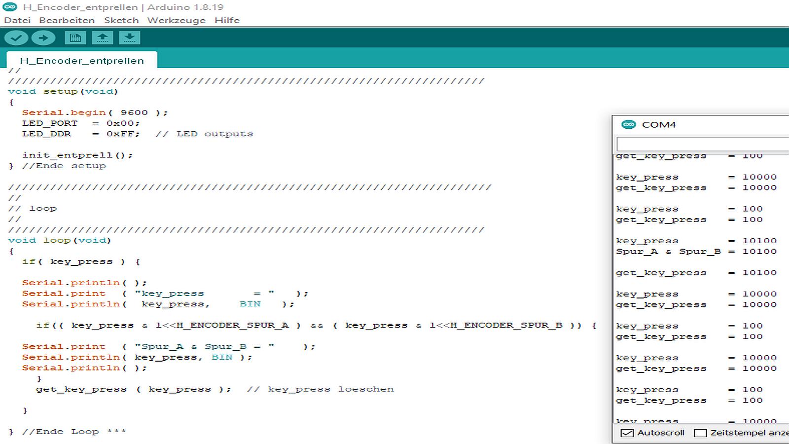
Arduino Code und Serienmonitor
Serial.println( key_press, BIN ); if(( key_press & <H_ENCODER_SPUR_A) && ( key_press & <H_ENCODER_SPUR_B )) { Serial.print( "Spur_A & Spur_B = " ); Serial.println( key_press, BIN ); } get_key_press( key_press ); // key_press loeschen } } //Ende Loop AAA COM4 get_key_press = 100 key_press = 10000 get_key_press = 10000 key_press = 100 get_key_press = 100 key_press = 10100 Spur_A & Spur_B = 10100 get_key_press = 10100 key_press = 10000 get_key_press = 10000 key_press = 100 get_key_press = 100 get_key_press = 10000 get_key_press = 10000 key_press = 100
in „Peter Dannegger´s ( PeDa ) Entprellroutine in ein Arduino Sketch einbinden“ · Mikrocontroller und Digitale Elektronik · · Screenshots

-
PDF
B400_ALPS-RK09K.pdf
Operating RK09K1110AK4 15 Horizontal Flat 1 RK09K1110AH8 20 type RK09K1110B1V 5 1B Hʹ6.5mm RK09K1110A0J 20 10 Knob 100 5 RK09K11100E9 With 50 Horizontal RK09K1110B1R 15 15A type 6 Hʹ10mm RK09K1110B26 20 RK09D1130C1B 10 RK09D1130C2P Without 25 RK09D1130A1L 50 Vertical RK09D1130A1N
in „Eagle Lib Alps RK09K“ · Platinen ·
-
Datei
HiQwen3_5_9B.txt
christoph@Ryzen5:~$ docker exec -it ollama ollama --verbose run qwen3.5:9B >>> Hi! Thinking... Thinking Process: 1. **Analyze the Request:** * Input: "Hi!" * Intent: Greeting. * Expected Response: A friendly, appropriate greeting in return. 2. **Determine the Tone:** * Friendly
-
PDF
ds18b20_pre1.pdf
Using DS18B20 digital temperature sensor on AVR microcontrollers Description and application Version 1.0 (Preliminary) Research Project Documents Gerard Marull Paretas September 2007 Index 1. Introduction.......
in „Atmega 8 + dallas 18s20 + Neuling (never ending story)“ · Mikrocontroller und Digitale Elektronik ·
-
PDF
MAX16801A-MAX16802B.pdf
♦ 50% (MAX16801A/MAX16802A) or 75% 2 LED driver. The MAX16801A/MAX16802A areoffered with (MAX16801B/MAX16802B) Maximum Duty Cycle A 50% maximum duty cycle.The MAX16801B/MAX16802B ♦ Available in a Tiny 8-Pin µMAX Package / are offered with 75% maximum duty cycle. These devices B are available in an
in „High Brightness LEDs > 50W µC als regelbare KSQ“ · Mikrocontroller und Digitale Elektronik ·
-
PDF
NTC_B57560G1303F.pdf
3478 3450 3492 ±1% B57560G1103+000 10 k 8307 3478 3450 3492 ±1% B57560G1103+002 20 k 8415 3992 3970 ±1% 4006 B57560G0203+000 20 k 8415 3992 3970 ±1% 4006 B57560G0203+002 30 k 7002 3973 3944 3988 ±1% B57560G1303+005 30 k 7002 3973 3944 3988 ±1% B57560G1303+007 50 k 8403 3992 3970 ±1% 4006 B57560G0503+000 50 k 8403 3992 3970 ±1% 4006 B57560G0503+002 100 k 8304 4072 4036 4092 ±1% B57560G1104+000 100 k 8304 4072 4036 4092 ±1% B57560G1104+002 1400
in „Wie die Temperatur berechnen“ · Analoge Elektronik und Schaltungstechnik ·
-
Datei
HAL_NAND_Write_Page_8b.c
NumPageToWrite number of pages to write to block * @retval HAL status */ HAL_StatusTypeDef HAL_NAND_Write_Page_8b(NAND_HandleTypeDef *hnand, NAND_AddressTypeDef *pAddress, uint8_t *pBuffer, uint32_t NumPageToWrite) { __IO uint32_t index = 0U; uint32_t tickstart = 0U; uint32_t deviceaddress = 0U, size = 0U, numPagesWritten
in „STM32 - FMC: NAND Write blockiert Interrupts“ · Mikrocontroller und Digitale Elektronik ·
-
Datei
EEPROM-Werte-Speichern_Tisch_20200129b.ino
/* #include <EEPROM.h> int drehungenende = 1200; // Maximale Tischhöhe 118cm Hub 55cm int drehungenlinks; int drehungenrechts; void setup() { drehungenlinks = drehungenende; drehungenrechts = drehungenende; EEPROM.put( 0, drehungenlinks); EEPROM.put(2, drehungenrechts); } void loop() { }*/ #include <EEPROM.h> int drehungenende = 1200; // Maximale Tischhöhe 118cm Hub 55cm int mp = 13; // Messpunkt mit LED int drehungenlinks; int drehungenrechts; void setup() { pinMode(mp,OUTPUT); EEPROM.get(0, drehungenlinks); EEPROM.get(2, drehungenrechts); } void loop() { if(drehungenlinks == drehungenrechts)
in „Arduino put() get() ein ppar Fragen dazu.“ · Mikrocontroller und Digitale Elektronik ·
-
Datei
EEPROM-Werte-Speichern_Tisch_20200130b.ino
#include <EEPROM.h> int acpin = A4; bool volt; bool spggut; unsigned long spggutstart; unsigned long spggutist; unsigned long spggutvz = 45; bool spgguta; bool speichern; int mp = 13; // Messpunkt, LED int drehungenende = 1200; // 1200Maximale Tischhöhe 118cm Hub 55cm int drehungenlinks; int drehungenrechts; bool led; //led MF zur Sichtkontrolle unsigned long ledstart; unsigned long ledist; unsigned long ledvz = 500; void setup() { drehungenlinks = drehungenende; drehungenrechts = drehungenende; pinMode(mp, OUTPUT); } void loop() { if(analogRead(acpin) > 500){volt = HIGH;} // >12V Tatfo hat 15VAC an Steuerwicklung
in „Arduino put() get() ein ppar Fragen dazu.“ · Mikrocontroller und Digitale Elektronik ·
-
PDF
rev.b_650mA_KSQ.pdf
10-24VDC GND MBRS240 + GND 47uF +LED_1 -LED_1 330uH GND 350mA 650mA 700mA MBRS240 Rx 1.5 1.2 1.2 8 5 PWM +5VDC_1 Rx 1.5 1.2 1.1 R R R 6 Rx X 1.2 1.1 x x x 7 0 PWM +5VDC_2 N 2 1 G 3 PWM +5VDC_3 1 4 GND GND 330pF MC34063 GND GND GND + MBRS240 47uF +LED_2 330uH -LED_2 GND MBRS240 350mA 650mA 700mA 8 Rx 1.5 1.2 1.2 5 Rx 1.5 1.2 1.1 R R R 6 Rx X 1.2 1.1 x x x 7 K D 2 1 N 3 G 1 4 GND 330pF MC34063 GND GND + MBRS240 47uF +LED_3 -LED_3 330uH GND MBRS240 350mA 650mA 700mA Rx 1.5 1.2 1.2 8 Rx 1.5 1.2 1.1 5 Rx X 1.2 1.1 x x x 6 D 7 0 N 2 1 G 3 1 GND 4 330pF MC34063 GND GND
in „Konstantstromquelle MC34063 überhitzt!“ · Mikrocontroller und Digitale Elektronik ·
-
Datei
tiny_oled_spi_3wire_b.ino
Zeichen auf ein 16x16 Zeichen vergroessern z1= pgm_read_byte(&(font8x8h[ch-' '][i])); z2[i]= 0; for (b= 0; b< 8; b++) { if (z1 & (1 << b)) { z2[i] |= (1 << (b*2)); z2[i] |= (1 << ((b*2)+1)); } } } for (i= 0; i< 8; i++) { z= z2[i]; if ((!textcolor)) z= ~z; z= z >> 8; spi_out(z); spi_out(z); } gotoxy(aktxp
in „ATtiny85 benötige Taster und kein freier Port“ · Mikrocontroller und Digitale Elektronik ·
-
PDF
WH1602B-TMI-JT__selbstgesucht_.pdf
backlight B→EL, Blue green A→LED, Amber D→EL, Green R→LED, Red W→EL, White O→LED, Orange F→CCFL, White G→LED, Green Y→LED, Yellow Green T→LED, White h LCD Mode: B→TN Positive, Gray T→FSTN Negative N→TN Negative,
in „Winstar WH1602B LCD-Display am Atmega16“ · Mikrocontroller und Digitale Elektronik ·
-
PDF
B400_RV-3049-C2.pdf
Trickle-charge circuitry, an integrated Temperature Sensor with digital-output and offers 8 Bytes Option B: Default RAM and 2 Bytes EEPROM for customer's application. Accuracy ± 3ppm / @ +25°C The calendar function tracks year and leap -year flags. The clock tracks Accuracy ± 5ppm / 0°C to +50°C second, minute
in „Uhrbaustein gesucht“ · Mikrocontroller und Digitale Elektronik ·
-
PDF
B101EW05_V0.pdf
3 these 6 bits pixel data. G2 Green Data 2 G1 Green Data 1 G0 Green Data 0 (LSB) Green-pixel Data B5 Blue Data 5 (MSB) Blue-pixel Data B4 Blue Data 4 Each blue pixel's brightness data consists of B3 Blue Data 3 these 6 bits pixel data. B2 Blue Data 2 B1 Blue Data 1 B0 Blue Data 0 (LSB) Blue-pixel Data
in „Handydummy (Attrappe)mit richtigem Display 10Zoll - u.a.Motorola Xoom“ · Mikrocontroller und Digitale Elektronik ·
-
Datei
Backup-FW-UTi260B-EEVBlog.txt
https://www.eevblog.com/forum/thermal-imaging/uti260b-uti690b-firmware-backup-script/msg4964089/#msg4964089 Hi i make a simple script to backup some firmware files of your device... 1) Copy these 2 folders to the SD card: Upgrade FWBackup 2) Insert SD card
in „Wärmebildkamera - Kaufempfehlung“ · Mechanik, Gehäuse, Werkzeug ·
-
Datei
FreeSans6pt7b.h
0x30, 0x0C, 0x06, 0x03, 0x01, 0xC0, 0x60, 0x30, 0x18, 0x06, 0x03, 0x00, 0xFF, 0xC0, 0xFB, 0x6D, 0xB6, 0xDB, 0x6D, 0xB6, 0xE0, 0x84, 0x10, 0x84, 0x10, 0x84, 0x10, 0x84, 0x10, 0x80, 0xED, 0xB6, 0xDB, 0x6D, 0xB6, 0xDB, 0xE0, 0x30, 0x60, 0xA2, 0x44, 0xD8, 0xA1, 0x80, 0xFF, 0xC0, 0xC6, 0x30, 0x7E, 0x71,
in „Arduino Adafruit GFX Fonts für OLED Displays erzeugen“ · Mikrocontroller und Digitale Elektronik ·
-
Datei
FreeSans6pt7b.h
0x30, 0x0C, 0x06, 0x03, 0x01, 0xC0, 0x60, 0x30, 0x18, 0x06, 0x03, 0x00, 0xFF, 0xC0, 0xFB, 0x6D, 0xB6, 0xDB, 0x6D, 0xB6, 0xE0, 0x84, 0x10, 0x84, 0x10, 0x84, 0x10, 0x84, 0x10, 0x80, 0xED, 0xB6, 0xDB, 0x6D, 0xB6, 0xDB, 0xE0, 0x30, 0x60, 0xA2, 0x44, 0xD8, 0xA1, 0x80, 0xFF, 0xC0, 0xC6, 0x30, 0x7E, 0x71,
in „Arduino Adafruit GFX Fonts für OLED Displays erzeugen“ · Mikrocontroller und Digitale Elektronik ·
-
Datei
r3g3b2.txt
0 0 0 0 0 85 0 0 170 0 0 255 0 36 0 0 36 85 0 36 170 0 36 255 0 72 0 0 72 85 0 72 170 0 72 255 0 109 0 0 109 85 0 109 170 0 109 255 0 145 0 0 145 85 0 145 170 0 145 255 0 182 0 0 182 85 0 182 170 0 182 255 0 218 0 0 218 85 0 218 170 0 218 255 0 255 0 0 255 85 0 255 170 0 255 255 36 0 0 36 0 85 36 0 170 36 0 255 36 36 0 36 36 85 36 36 170 36 36 255 36 72 0 36 72 85 36 72 170 36 72 255 36 109 0 36 109 85 36 109 170 36 109 255 36 145 0 36 145 85 36 145 170 36 145 255 36 182 0 36 182 85 36 182 170 36 182 255 36 218 0 36 218 85 36 218 170 36 218 255 36 255 0 36 255 85 36 255 170 36 255 255 72 0 0 72
in „Mit paint.net ein 8Bit Bild erstellen.“ · Softwareentwicklung ·
-
Datei
ESJOG_3b_V_1.0.c
******/ // Timer für Zeiterzeugung /* tmr1 running on full MCU clock Fast mit icr1 als top */ TCCR1B = 0x00; // Register auf Null gesetzt und stoppt Timer TCCR1B = 0x03; //_BV(CS11)|_BV(CS10);//_BV(WGM13)|_BV(WGM12) // Timer 1 wird gestartet und mit dem // 1 / 64 CPU-Takt betrieben // Bit 3 CTC1 (Clear
in „WinAVR compiliert nicht mehr richtig“ · Mikrocontroller und Digitale Elektronik ·
-
Datei
DS18B20_GETADDRESS.a51
r7 to the bus ; uses r1 for a loop writeByte: mov r1,#8 write8BitsLoop_1: mov a,r7 anl a,#00000001b ; get lsb of a call write ; write lsb of a mov a,r7 ; rotate r7 rr a ; to get next bit mov r7,a ; djnz r1,write8BitsLoop_1 ret ; read the next 8 bits from the bus and write them into r7 ; uses r1 for
in „Timing Probleme 1-Wire“ · Mikrocontroller und Digitale Elektronik ·
-
Datei
font8x8b_vertikal.h
uint8_t font8x8[][8] = { {0x00,0x01,0x01,0x01,0x01,0x01,0x01,0x00}, // Ascii 0 = ' ' {0xfc,0x87,0x4b,0x03,0x4b,0x33,0x87,0xfc}, // Ascii 1 = ' ' {0xfc,0xfe,0xb7,0xff,0xb6,0xce,0xfe,0xfc}, // Ascii 2 = ' ' {0x00,0xd8,0xfc,0xfc,0xf9,0x70,0x20,0x00}, // Ascii 3 = ' ' {0x00,0x20,0x70,0xf9,0xfd,0xf9,0x70,0x20
in „besser lesbarer 8x8 Zeichensatz für GLCD“ · Mikrocontroller und Digitale Elektronik ·
-
Datei
font8x8b_horizontal.h
0xc8,0x88,0xc8,0x7e,0x3e,0x00}, // Ascii 65 = 'A' {0xfe,0xfe,0x92,0x92,0x92,0xfe,0x6c,0x00}, // Ascii 66 = 'B' {0x38,0x7c,0xc6,0x82,0x82,0xc6,0x44,0x00}, // Ascii 67 = 'C' {0xfe,0xfe,0x82,0x82,0xc6,0x7c,0x38,0x00}, // Ascii 68 = 'D' {0xfe,0xfe,0x92,0x92,0x92,0x82,0x82,0x00}, // Ascii 69 = 'E' {0xfe,0xfe,0x90,0x90,0x90,0x80,0x80,0x00
in „besser lesbarer 8x8 Zeichensatz für GLCD“ · Mikrocontroller und Digitale Elektronik ·
-
Datei
HIPP_TIMER_V1.08B.ino
*****************************************************/ void init_InputCapture() { TCCR1A = 0; TCCR1B = 0; TIMSK1 = 0; TCNT1 = 0; // ICNC1 ICES1 – WGM13 WGM12 CS12 CS11 CS10 TCCR1B = (1<<ICNC1) | (1<<CS10); // 16MHZ Clk, ICU Filter EN, ICU Pin falling TIFR1 = 1<<ICF1; // Clear ICF1. Clear pending interrupts
in „AVR T1 Capture Problem - Meinung erbeten“ · Mikrocontroller und Digitale Elektronik ·
-
PDF
10-TFP09-2-12B.pdf
.0Y.OM.T WWW .0Y.O .W W .0Y.OM.W WWW .0 .O .W WWW.0Y.O .W WWW .0YCM .W WW W.0YCMM.W WWW.1 YCM . WWW.11045TFP09-2-12BSY 卡M 外焊式 手機 WWW.00YOM.T 內W內存W.自Y.OM.W WW W.00.OM.W WW W.00.OM.W WW W. 0.OM.W WW W10YC M.W WWWW10YCOM.W WWW.00YO M.W W W W.10Y OM.W WWW.00.OO.TW W WWW. 0. O.TW W WW.00. O. W .TW W WW.10. O. W W WW.00.OM. W M.TW W WW.10.OM.TW W WW10YCOM.W OM..W W WW.0YCOM.T WWW.10YCOMTT .OM . W W .0Y.OM.T WWW..0.CO. .OM.T WWW .0 .O .W W WW .0..M 0 .O .W WWW .0 .O .W WWWW.10.C 00 .O .W WWW.10.CM .W WWW.0Y. .10YCM .W WWW.0YYOM.T WW .0Y W.0 YOMMT WWW.0Y.OM.W WWW .0 W.0Y.OM.W WW W.0Y.OM.W WWWW.0 W W.00
in „microSD Card Socket SMD“ · Mikrocontroller und Digitale Elektronik ·
-
PDF
VS1838B_Infrared_Receiver_Module.pdf
Infrared Receiver Module Ę@34I : VS1838B 1. ;: ●(),&' ●()*+ IC' ●,-./01234' ●56789:' ●8;<=>?@67' ●ABCDE' 2. F+: ■GHIJ(KL,BG,MNO,PO) ■Q+BI (RIO,BST,BU) ■VWX@BIYZ[\' 3. F+B‡ˆ‰ 4. Š‹ˆ‰ www.DataSheet4U.com Infrared Receiver Module Ę@34I : VS1838B
in „Problem mit VS1838B Infrared Receiver“ · Mikrocontroller und Digitale Elektronik ·
-
PDF
0900766b808e044e.pdf
TLP523 e 80 w W u p ( c ) TLP523 r r A 60 c C120 w ( TLP523 -2, -4 l P TLP523 -2, -4 o o n e I e t b 40 b p 80 w w s o o i A A d 40 20 0 0 -20 0 20 40 60 80 100 120 -20 0 20 40 60 80 100 120 Ambient temperature Ta (℃) Ambient temperature Ta (℃) I – V IFP – D R F F 5000 100 3000 Pulse width ≤ 100μs Ta
in „Problem mit Optokoppler“ · Mikrocontroller und Digitale Elektronik ·
-
PDF
NetzteilFet_Rev1.2B.pdf
R36 J R 3 I 1k 1 I 2 T J 1 0,47/5W I 1 2 5 M R 3 R29 C K 5W P Q 5W S Q R8 1k U 1 R25 1k 0 3 0,47/5W B C 5 9 P 2 K P F F J R17 F R37 J R I 1k 0 0,47/5W I / 2 R30 2 µ 5W 1 1 5W V 0 Q Q B 0 R26 0 3 2 T 1k 3 5 0,27/5W X S 2 1 5 F P 1 M R38 P F I JR18 0,47/5W I 1k MSTBV2 1 S 5W 2 1 2 1 F 1 B KK2 X2 X1 MSTBV2
in „Lineares Labornetzgerät schwingt“ · Analoge Elektronik und Schaltungstechnik ·
-
PDF
DE102017203801B3_all_pages.pdf
(19) *DE102017203801B320180308* (10) DE 10 2017 203 801 B3 2018.03.08 (12) Patentschrift (21) Aktenzeichen: 10 2017 203 801.2 (51) Int Cl.: H05B 37/02 (2006.01) (22) Anmeldetag: 08.03.2017 (43) Offenlegungstag: – (45) Veröffentlichungstag
in „Effiziente LED Beleuchtung modular, wie am besten.“ · Haus & Smart Home ·
-
PDF
ALPS_EM20B_LEDs_Pins.pdf
!WERT !BAUTEIL 9 11 12 10 VA VB !WERT 3 1 S2 B 2 4 S1 A GA GB !BAUTEIL 8 7 6 5
in „Mehrere neue ALPS EM20B4014A01 Drehimpulsgeber mit 31 Bargraph-LEDs“ · Markt ·
-
PDF
BSB__CNetNT_v3b.pdf
Stromregler spannungs quelle Einstellung für Einstellung für SollSpannung Maximalstrom BSB_µCNetNT_v3b
in „Labornetzgerät - Fragen zum Schaltplan“ · Analoge Elektronik und Schaltungstechnik ·
-
PDF
4415-0057_LNG_V1b.pdf
0u22 J5 D12 GND 3 CC-MODE -SENSE 2 2 R58 J5 470R R7 4 Safety Resistor -OUT 0R39/A, 5-10W R56 R55 -OUT B +15V V+ R54 B 100R 100R R53 82R 1K 7 7 U2C 7 c c 1 N1 c R14 R13 D7 V U3B V U1B RV1 V U2B Q51 1K5 10K 5V1 e C54 e C53 100K C52 e ZD51 2N3904 R2 e TL081 0u1 e TL081 0u1 NULL ADJ 0u1 e TL081 33V, 1W D5
in „Labornetzgerät - Fragen zum Schaltplan“ · Analoge Elektronik und Schaltungstechnik ·
-
PDF
ACDC_EL750B_Operating___Service.pdf
ACDC_EL750B_Operating___Service.pdf
in „Stromsenke / el. Last“ · Analoge Elektronik und Schaltungstechnik ·
-
PDF
MAX38640A-MAX38643B.pdf
) with IN 50mV hysteresis (typ.). Table 2. MAX3864xB Preprogrammed Output Voltage Table PART NUMBER OUTPUT VOLTAGE (V) MAX3864xB-50 5.0 MAX3864xB-45 4.5 MAX3864xB-40 4.0 MAX3864xB-33 3.3 MAX3864xB-30 3.0 MAX3864xB-275 2.75 MAX3864xB-25 2.5 MAX3864xB-20 2.0 MAX3864xB-18 1.8 MAX3864xB-15 1.5 MAX3864xB-12 1.2 MAX3864xB-10 1.0 MAX3864xB-09 0.9 MAX3864xB-08 0.8 MAX3864xB-07 0.7 MAX3864xB-065 0.65 MAX3864xB-06 0.6 MAX3864xB-055 0.55 MAX3864xB-05 0.5 www.maximintegrated.com
in „(Ultra) Low Power System mit 3.3V ?“ · Mikrocontroller und Digitale Elektronik ·
-
PDF
RCD_Typ_B_Technik-Fibel_Siemens.pdf
22 2.4.3 SIQUENCE allstromsensitive FI-Schutzschalter Typ B und Typ B+ 23 2.4.4 SIQUENCE allstromsensitive FI/LS-Schalter Typ B und Typ B+ 26 2.4.5 FI-Blöcke für den Anbau an Leitungsschutzschalter 27 2.4.6 SIGRES-FI-Schutzschalter (für erschwerte Umgebungsbedingungen
-
PDF
0900766b80eaef6e.pdf
-2 24 10.5 39 914 630 V23054D2020B110 1393813-3 32 14.5 50 975 1050 V23054D2021B110 1393813-4 32 14.5 50 975 1050 V23054D2021B112 1393813-5 60 29 94 947 3800 V23054D2026B110 1393813-6 60 29 94 947 3800 V23054D2026B112 1393813-7 24 10.5
in „Suche Daten zu Kammrelais von Siemens“ · Mikrocontroller und Digitale Elektronik ·
-
PDF
WS2812B_VS_WS2812.pdf
www.world-semi.com 2. Mechanical properties comparison . The mechanical size and pin drawing of WS2812B The mechanical size and pin drawing of WS2812 Through drawing comparison, it is easy to find that the,, WS2812B WS2812 consistent in size, but the PAD number of the former are reduced to 4 Pin, with
in „[Mitbestellung] SMD5050 RGB-LED mit integriertem 8-bit PWM Controller“ · Markt ·
-
PDF
JVC_rv-nb20b_Schema.pdf
8 9 7 7 R9176 C F 1 5 7 9 D R 1 1 1 2 B4070 B4004 C9150 DI901 7 7 7 1 3 3 B4073 R R R C R9238 5 3 3 3 5 R R 1 R R R 3 C 7 C 3 2 3 4 5 9 R9275 5 C9187 1 1 1 1 IC904 R B4078 3 B4071 R R R R 8 6 Q3571 D 0 4 4 4 R9151 B B 9 9 C C 4 C9149 R9152
in „JVC Boomblaster - 12V/230V unterschiedliche Bassstärke“ · Analoge Elektronik und Schaltungstechnik ·
-
PDF
Crystals_RevB_20Apr2013.pdf
Crystals_RevB_20Apr2013.pdf
-
 Bild
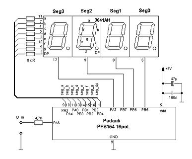
Schaltplan mit Padauk-Mikrocontroller und 7-Segment-Anzeige
Seg3 Seg2 Seg1 Seg0 11 7 4 2 1 10 5 3 a b c d e f g DP 3641AH a b c d e f g DP 12 9 8 6 8 x R 4,7k D_in PA3 PA0 PB1 PB3 PA7 PB7 PB6 PB5 PA4 PB0 PB2 PB4 9 10 11 13 14 15 1 5 Vdd +5V 47µ 100n Padauk PFS154 16pol PA6 GND 9
in „4-Digit LED 7-Segment Anzeigetreiber mit Padauk PFS154-S16“ · Projekte & Code · · Schaltpläne
-
 Bild
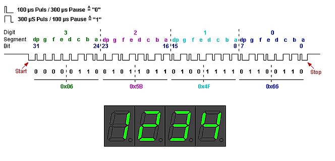
Analyse eines seriellen Datenprotokolls für eine 7-Segment-Anzeige
100 µs Puls / 300 µs Pause = "0" 300 µS Puls / 100 µs Pause = "1" Digit 3 2 1 0 Segment dp g f e d c b a Bit 31 24 23 16 15 8 7 0 Start 0 0 0 1 1 0 0 0 1 0 1 1 0 1 1 0 1 0 1 1 1 0 1 1 0 1 1 0 Stop 0x06 0x5B 0x4F 0x66
in „4-Digit LED 7-Segment Anzeigetreiber mit Padauk PFS154-S16“ · Projekte & Code · · Screenshots
-
 Bild
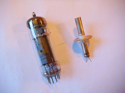
Elektronenröhre und eine Glühlampe
EL84
in „Witzige "HF Wege" - Berichte“ · HF, Funk und Felder · · Fotos
-
PDF
BLK-MD-SPK-B_AT______0514.pdf
博陆科电子 BLK-MD-SPK-B AT 命令应用指导 BLK-MD-SPK-B AT 命令应用指导 2011-03 第 1 页 共 23 页 博陆科电子 BLK-MD-SPK-B AT 命令应用指导 目录 1. 蓝牙应用状态介绍......................................................................................................
in „A2DP Bluetooth Modul China eBay“ · HF, Funk und Felder ·
-
PDF
Siemens_B1023_Norma_MP14.pdf
750 V AC Strombereiche : 2 mA - 10 A DC/AC Widerstandsbereiche : 200 Ohm - 100 MOhm Dezibel : -160 dB ••• +160 dB Temperaturmeßbereich : -20°C - +1200°C ~ Frequenzbereiche : 10 kHz - 130 kHz Das Gerät entspricht dem neuesten Stand der Technik und erfüllt die Sicherheitsvorschriften gemäß DIN 57411/ VDE
-
PDF
behringer_eurolive_b112d_sm.pdf
A06 k R169 2 1 VR3-B R174 2 - 4 E R152 100KW k G1 G2 R71 2 R74 0R159 2 0C162 0 0E 1 1 2 R171 1 R170 2 X7 VR2-B 1u D +15V E G1 100KW G2 T20 +5VDC VR4-B AGND R7 T19 3906 B +5VDC G DGND 50KB 10k C G1 G2 LD3 DGND VR1-B WIRELESSA
in „Behringer B112D Funktionsweise Netzteil“ · Analoge Elektronik und Schaltungstechnik ·
-
PDF
AEG_Power_Supply_V3b.pdf
1 2 3 4 Q1 2N3055 R2 5V REG Gl1 TBD C3 B250C5600 D 100u, 25V D R1 GND TBD C2 4700uF, 63V PINS DUPLICATED SHOWN WITH JUNCTION C1 J1A GND 16 GND TR1 15 +15V SPECIAL U1 4700uF, 63V 7 6 14 +5V OUT 1 VC Vout 13 20V D2 12 5 CL 10 K1 11 24VAC GND
in „Netzteilkarte von 1990 defekt. LM723CH“ · Analoge Elektronik und Schaltungstechnik ·
-
PDF
Maxi_USB_Board_RevB_mit_Bohrungen.pdf
Maxi_USB_Board_RevB_mit_Bohrungen.pdf
in „Lerncomputer MC 51“ · Mikrocontroller und Digitale Elektronik ·
-
PDF
Seiten_aus_nsecQuarzfilter_Rev2b.pdf
bevorzuge ich Doppelloch-Kerne, die eine wesentlich geringere Streuung und damit Dämpfung zeigen (z.B. BN43-2402). Diese zusätzliche Dämpfung ist leicht zu messen, indem man im Aufbau die beiden Endglieder direkt mit- einander verbindet ("back-to-back"). Bild 34 zeigt Beispiele von verschiedenen Trafos
-
PDF
Z-LASER_Produktdatenblatt_ZM18B.pdf
ZM18B »» Rote oder infrarote Wellenlängen verfügbar »» Optische Ausgangsleistung bis zu 120mW / 160mW IR »» Gauss/homogene Linien, Punkt sowie diverse DOE Optiken verfügbar »» 5 bis 30VDC Versorgungsspannung
in „Spitzenwertdetektor Laserstrahlmessung“ · Analoge Elektronik und Schaltungstechnik ·
-
PDF
B156XW03_V.2.pdf
signals and LCD pixel format. 1 1366 1st Line R G B R G B R G B R G B 768th Line R G B R G B R G B R G B B156XW03 Document Version : 1.2 17 of 31 Product Specification AU OPTRONICS CORPORATION 6.2 The Input Data Format Signal Name Description R5 Red Data
in „Pollin LVDS-Board an B156XW03 Display“ · Mikrocontroller und Digitale Elektronik ·