-
PDF
D120425D.PDF
TG12864B-13 ■ Series ■ Electrical Characteristics Standard value Display Format 128 X 64 DOTS ITEM Symbol Condition UNIT Min. Typ. Max. Drive Method 1/64 Duty ; 1/9 Bias Supply Voltage For Logic V DD SS -- 4.5 5.0 5.5 V STN Gray Positive Supply Voltage For LCD VDDV 0 -- 8.8 9.0 9.2
in „128x64 Grafik LCD An Atmega 8/16/32“ · Mikrocontroller und Digitale Elektronik ·
-
PDF
GLCD-TG12864B-05_128x64_Pixel.PDF
TG12864B-05 ■ Series ■ Electrical Characteristics Standard value Display Format 128 X 64 DOTS ITEM Symbol Condition UNIT Min. Typ. Max. Drive Method 1/64 Duty ; 1/9 Bias Supply Voltage For Logic V DD SS -- 4.5 5.0 5.5 V Supply Voltage For LCD VDDV 0 -- -- 9.0 -- V LCD Type STN/Transflective
in „Projet um die Kapazität von Akkus zu messen“ · Mikrocontroller und Digitale Elektronik ·
-
PDF
Data_TG12864.PDF
TG12864B-05 ■ Series ■ Electrical Characteristics Standard value Display Format 128 X 64 DOTS ITEM Symbol Condition UNIT Min. Typ. Max. Drive Method 1/64 Duty ; 1/9 Bias Supply Voltage For Logic V DD SS -- 4.5 5.0 5.5 V Supply Voltage For LCD VDDV 0 -- -- 9.0 -- V LCD Type STN/Transflective
in „Fehler in der Anzeige bei GLCD“ · Mikrocontroller und Digitale Elektronik ·
-
 Bild
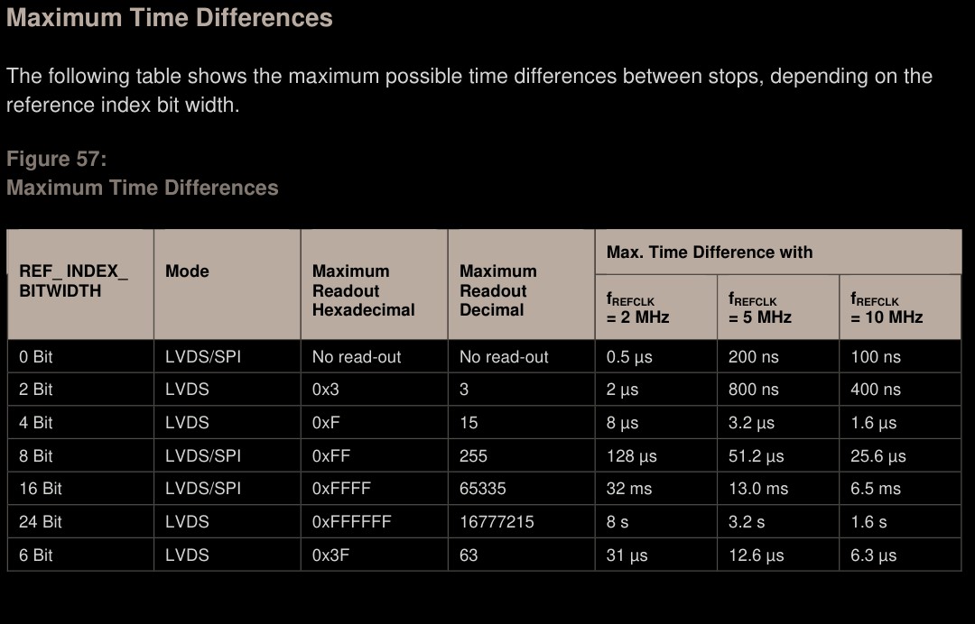
Tabelle der maximalen Zeitdifferenzen zwischen Stopps
Maximum Time Differences REF_INDEX_BITWIDTH Mode Maximum Readout Hexadecimal Maximum Readout Decimal Max. Time Difference with fREFCLK = 2 MHz fREFCLK = 5 MHz fREFCLK = 10 MHz 0 Bit LVDS/SPI No read-out No read-out 0.5 µs 200 ns 100 ns 2 Bit LVDS 0x3 3 2 µs 800 ns 400 ns 4 Bit LVDS 0xF 15 8 µs 3.2 µs 1.6 µs 8 Bit LVDS/SPI 0xFF 255 128 µs 51.2 µs 25.6 µs 16 Bit LVDS/SPI 0xFFFF 65535 32 ms 13.0 ms 6.5 ms 24 Bit LVDS 0xFFFFFF 16777215 8 s 3.2 s 1.6 s 6 Bit LVDS 0x3F 63 31 µs 12.6 µs 6.3 µs
in „TDC(AS6501) als Phasenvergleicher“ · Mikrocontroller und Digitale Elektronik · · Screenshots
-
PDF
datasheet__1_.pdf
EZ-USB Registers.” Page 2-2 Chapter 2. EZ-USB CPU EZ-USB TRM v1.9 2.5 EZ-USB Internal RAM FF Upper 128 SFR Space bytes Direct Addr 80 Indirect Addr 7F Lower 128 bytes Direct Addr 00 Figure 2-1. 8051 Registers Like the standard 8051, the EZ-USB 8051 core contains 128 bytes of register RAM at 00- 7F, and
in „Emitterschaltung und LM293D“ · Mikrocontroller und Digitale Elektronik ·
-
PDF
stm32f405rg.pdf
characteristics Table 40. Flash memory programming (continued) Symbol Parameter Conditions Min(1) Typ Max (1) Unit Program/eraseparallelism (PSIZE) = x 8 - 2 4 Program/eraseparallelism ERASE128KB Sector (128 KB) erase time (PSIZE) = x 16 - 1.3 2.6 s Program/eraseparallelism - 1 2 (PSIZE) = x 32 Program/
-
PDF
BRT_AN_033_BT81X-Series-Programming-Guide.pdf
Bits Bit 7 – 0: These bits define the backlight PWM output duty cycle. The valid range is from 0 to 128. 0 means backlight completely off, 128 means backlight in max brightness. Register Definition 83 – REG_PWM_DUTY Definition REG_PWM_HZ Definition 31 14 13 0 Reserved r/w Offset: 0xD0 Reset Value: 0xFA
in „STM32F407 DISCOVERY mit EVE3 50GTPC von MatrixOrbital“ · Mikrocontroller und Digitale Elektronik ·
-
PDF
ADNS2051.pdf
MICRO-CONTROLLER SDIO DRIVEN BY ADNS-2051 DETAIL "A" DETAIL "B" Figure 27. Read operation. 120 ns, MAX. HOLD DETAIL "A" 100 µs, MIN. SCLK MICROCONTROLLER TO ADNS-2051 60 ns, MIN. 0 ns, MIN. 120 ns, MAX. SDIO HANDOFF Hi-Z SDIO A1 A0 D 7 D6 120 ns, MIN. 0 ns, MIN. Figure 28. Microcontroller to ADNS-2051
in „Maussensor ADNS 2051 Bild auslesen“ · Mikrocontroller und Digitale Elektronik ·
-
PDF
SAM-V71Q-SAM-V71N-SAM-V71J_Datasheet.pdf
512 Kbytes 2 * 8 Kbytes 2 * 8 Kbytes 2 * 8 Kbytes 1 * 112 Kbytes 1 * 112 Kbytes 1 * 112 Kbytes 15 * 128 Kbytes 7 * 128 Kbytes 3 * 128 Kbytes Erasing the memory can be performed: by block of 8 Kbytes by sector of 128 Kbytes by 512-byte page for up to 8 Kbytes within a specific small sector Chip
in „Atmel SAMV71 CAN FD“ · Mikrocontroller und Digitale Elektronik ·
-
PDF
sony_str-de485_service_brazil.pdf
CERAMIC 220PF 5% 50V Q109 8-729-900-36 TRANSISTOR DTC124ES Q110 8-729-900-63 TRANSISTOR DTA124ES C136 1-128-813-11 CERAMIC 220PF 5% 50V Q111 8-729-900-63 TRANSISTOR DTA124ES C137 1-128-813-11 CERAMIC 220PF 5% 50V C138 1-128-813-11 CERAMIC 220PF 5% 50V < RESISTOR > C139 1-128-813-11 CERAMIC 220PF 5% 50V C140 1-128-813-11 CERAMIC 220PF 5% 50V C141 1-128-813-11 CERAMIC 220PF 5% 50V R101 1-247-823-91 CARBON 470 5% 1/4W C142 1-128-813-11 CERAMIC 220PF 5% 50V C143 1-128-813-11 CERAMIC 220PF 5% 50V R102 1-247-831-91
in „Reparaturanleitung Sony STR-DE585 FM STEREO/FM-AM RECEIVER Surround“ · Mikrocontroller und Digitale Elektronik ·
-
PDF
W2000_deutsch.pdf
Aufzeichung – digital durch A/D-Wandler • Automatische Signalmessungen • Feuchtigkeit Periode, Frequenz, Max, Min, Spitze-Spitze, Im Betrieb und bei Lagerung: • Durchschnittsberechnung und Darstellung Mean, RMS Bis zu 90% RH bei 30°C oder darunter. einstellbar: 4, 16, 64, 128 Im Betrieb: Bis zu 60% RH und max. 50°C • Einzelschuss Signalaufzeichung Lagerung: Bis zu 60% RH und max. 55°C Single-Shot-Taste zur getriggerten Signal- • Operationen • Höhe – Im Betrieb und bei Lagerung: aufnahme eines einzelnen Ereignisses
in „Oszilloskope; USB VS Standgerät“ · Mikrocontroller und Digitale Elektronik ·
-
PDF
W2000_deutsch.pdf
Aufzeichung – digital durch A/D-Wandler • Automatische Signalmessungen • Feuchtigkeit Periode, Frequenz, Max, Min, Spitze-Spitze, Im Betrieb und bei Lagerung: • Durchschnittsberechnung und Darstellung Mean, RMS Bis zu 90% RH bei 30°C oder darunter. einstellbar: 4, 16, 64, 128 Im Betrieb: Bis zu 60% RH und max. 50°C • Einzelschuss Signalaufzeichung Lagerung: Bis zu 60% RH und max. 55°C Single-Shot-Taste zur getriggerten Signal- • Operationen • Höhe – Im Betrieb und bei Lagerung: aufnahme eines einzelnen Ereignisses
in „ist 1000 Euros für "Texktronix TDS 684A" gut?“ · Markt ·
-
PDF
W2000_deutsch.pdf
Aufzeichung – digital durch A/D-Wandler • Automatische Signalmessungen • Feuchtigkeit Periode, Frequenz, Max, Min, Spitze-Spitze, Im Betrieb und bei Lagerung: • Durchschnittsberechnung und Darstellung Mean, RMS Bis zu 90% RH bei 30°C oder darunter. einstellbar: 4, 16, 64, 128 Im Betrieb: Bis zu 60% RH und max. 50°C • Einzelschuss Signalaufzeichung Lagerung: Bis zu 60% RH und max. 55°C Single-Shot-Taste zur getriggerten Signal- • Operationen • Höhe – Im Betrieb und bei Lagerung: aufnahme eines einzelnen Ereignisses
in „Wittig(welec) DSO W20xxA Open Source Firmware (Teil2)“ · Mikrocontroller und Digitale Elektronik ·
-
PDF
PartNumberBreakdown_ds.pdf
first letter of the suffix denotes product grade (accuracy, speed, etc.) For example, the first "A" in MAX631ACPA indicates 5% output accuracy. The product's full data sheet details the grades that apply to that part. The remaining three letters conform to the rules for three- letter suffixes. • Three-letter
in „SMD Bauteil identifizieren "4313"“ · Mikrocontroller und Digitale Elektronik ·
-
Datei
avr_cpm.asm
adrl,temp adc adrh,temp2 cpi zl,low(sectbuff+128) brne iplwriteloop cpi zh,high(sectbuff+128) brne iplwriteloop ;Init z80 ldi temp,0x00 mov z_pcl,temp ldi temp,0x20 mov z_pch,temp ldi trace,0 rcall printstr .db 13,"Ok, CPU is live!",13,0,0 main: ldi
in „CP/M auf ATmega88“ · Mikrocontroller und Digitale Elektronik ·
-
PDF
CSI93C86.pdf
CHARACTERISTICS (93C46/56/57/66) Limits V CC= V CC= VCC = 1.8V-6V* 2.5V-6V 4.5V-5.5V Test SYMBOL PARAMETER Min. Max. Min. Max. Min. Max. UNITS Conditions CSS CS Setup Time 200 100 50 ns CSH CS Hold Time 0 0 0 ns VIL 0.45V t DI Setup Time 400 200 100 ns V = 2.4V DIS IH DIH DI Hold Time 400 200 100 ns CL= 100pF PD1
in „asm Code für EEPROM 93C86“ · Mikrocontroller und Digitale Elektronik ·
-
PDF
datenblatt_pic.pdf
typ) = 10 ms TDEW (typ) = 10 ms TDEW (typ) = 10 ms T DEW (typ) = 4 ms Erase/Write cycle time T DEW (max) = 20 ms TDEW (max) = 20 ms TDEW (max) = 20 ms T DEW (max) = 8 ms (TDEW). See parameter # D122 in the electrical specs for more detail. Port Output Rise/Fall TioR, TioF (max) = 25 ns TioR, TioF (max) = 35 ns TioR, TioF (max) = 35 ns TioR, TioF (max) = 35 ns time (TioR, TioF). See (C84) (C84) (C84) (C84) parameters #20, 20A, TioR, TioF (max) = 60 ns TioR, TioF (max) = 70 ns TioR, TioF (max) = 70 ns TioR, TioF (max) = 70
in „Flußdiagramm Digitale stoppuhr auf PIC 16F84A“ · Mikrocontroller und Digitale Elektronik ·
-
PDF
16F84.pdf
typ) = 10 ms TDEW (typ) = 10 ms TDEW (typ) = 10 ms T DEW (typ) = 4 ms Erase/Write cycle time T DEW (max) = 20 ms TDEW (max) = 20 ms TDEW (max) = 20 ms T DEW (max) = 8 ms (TDEW). See parameter # D122 in the electrical specs for more detail. Port Output Rise/Fall TioR, TioF (max) = 25 ns TioR, TioF (max) = 35 ns TioR, TioF (max) = 35 ns TioR, TioF (max) = 35 ns time (TioR, TioF). See (C84) (C84) (C84) (C84) parameters #20, 20A, TioR, TioF (max) = 60 ns TioR, TioF (max) = 70 ns TioR, TioF (max) = 70 ns TioR, TioF (max) = 70
in „Probleme mit Taktversorgung auf Steckbrett“ · Mikrocontroller und Digitale Elektronik ·
-
PDF
GM47_Integrators_Manual_R1C.pdf
Parameters Description Command Possible Responses Show the current AT+CHSD • +CHSD: setting <mclass>,<maxRx>, <maxTx>,<sum>,<codings> • +CME ERROR: <err> • OK • ERROR Show if the command AT+CHSD=? • +CME ERROR: <err> is supported • OK • ERROR Shows information about HSCSD features supported by the ME/TA. <mclass> Description 2 Multislot class is 2 <maxRx> Description 2 Maximum number of receive timeslots that ME can use is 2 <maxTx> Description 1 Maximum number of transmit timeslots that ME can use is 1 <sum> Description 3 Total number of receive
in „GM47 GSM Spannungsversorgung aus LiIo-Akku“ · Mikrocontroller und Digitale Elektronik ·
-
PDF
datasheet.pdf
Register Baud Rate Timer 1 f SMOD Mode 12-clock mode 6-clock mode OSC C/T Mode Reload Value Mode 0 Max 1.67 MHz 3.34 MHz 20 MHz X X X X Mode 2 Max 625 k 1250 k 20 MHz 1 X X X Mode 1, 3 Max 104.2 k 208.4 k 20 MHz 1 0 2 FFH Mode 1, 3 19.2 k 38.4 k 11.059 MHz 1 0 2 FDH 9.6 k 19.2 k 11.059 MHz 0 0 2 FDH
in „Info zum SAB80C382 gesucht!“ · Mikrocontroller und Digitale Elektronik ·
-
 Bild
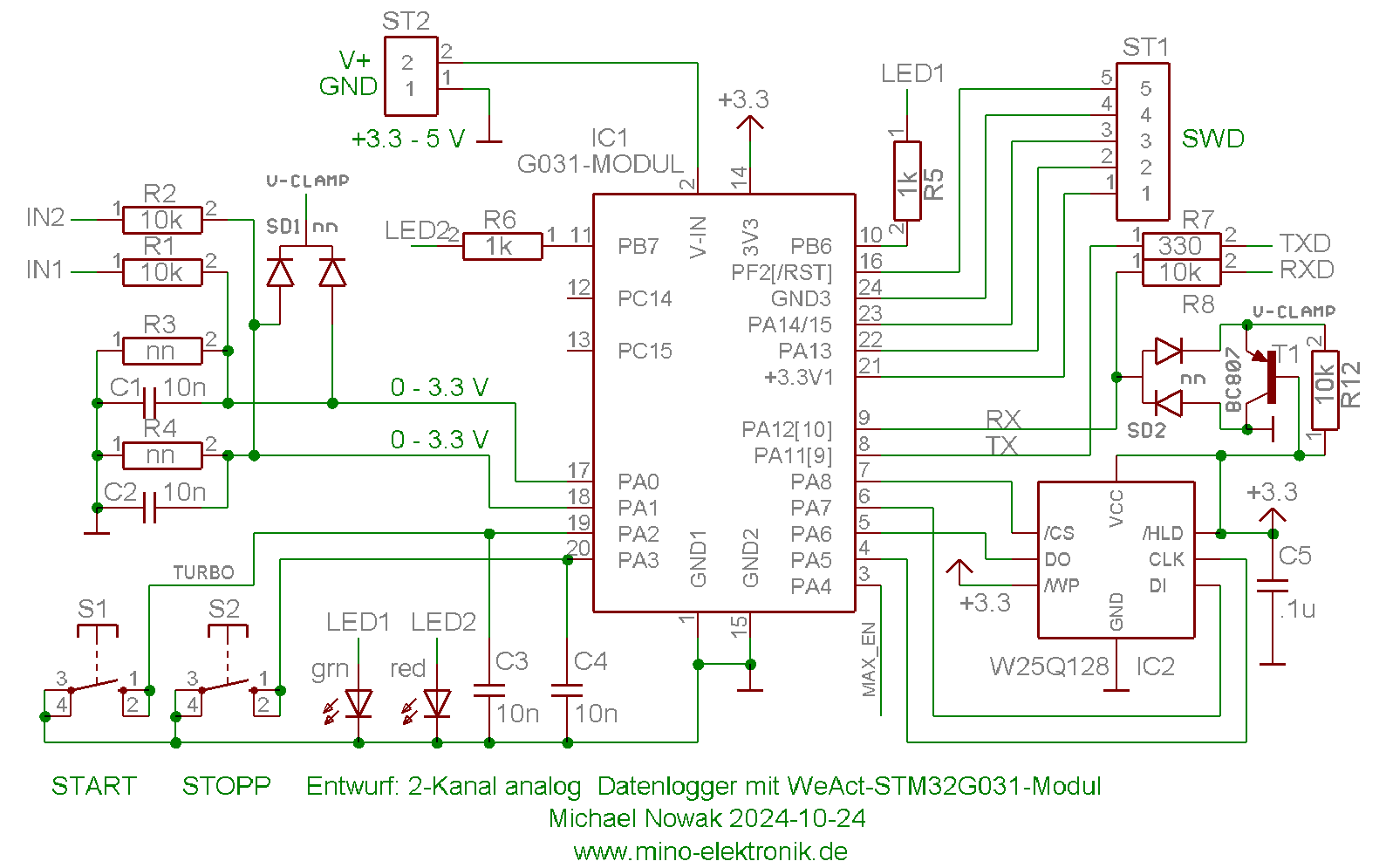
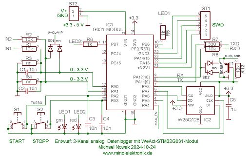
Schaltplan eines STM32G031-Moduls mit W25Q128 Flash
V, IN2, R2, 10k, IN1, R1, 10k, SDI, LED2, R6, 1k, PB7, PC14, PC15, PA0, PA1, PA2, PA3, GND1, GND2, MAX_EN, DI, CLK, /CS, /WP, DO, PA4, PA5, PA6, PA7, PA8, PA11, PA12, RX, TX, +3.3V1, GND3, PF2[/RST], PB6, 3V3, V-IN, IC1 G031-MODUL, ST1, SWD, R5, 1k, R7, 330, TXD, RXD, R8, 10k, U-CLAMP, BC807, T1, C5, .1u, W25Q128 IC2, +3.3, VCC, SD2, C1, C2, 10n, R3, R4, 10n, 0 - 3.3 V, S1, S2, LED1, LED2, grn, red, START, STOPP, TURBO, Entwurf: 2-Kanal analog Datenlogger mit WeAct-STM32G031-Modul, Michael Nowak 2024-10-24,
in „2-Kanal analoger Datenlogger, mobil“ · Projekte & Code · · Schaltpläne
-
 Bild
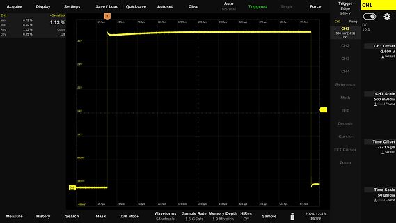
Oszilloskop-Messung einer Gleichspannung
FFT Decode Cursor Time Offset -223.5 us FFT Cursor Zoom Time Scale 50 us/div Coarse CH1 Min 0.73% Max 8.10% Avg 1.12% Dev 0.85% Count 128 -26.5us 23.5us 73.5us 123.5us 173.5us 223.5us 273.5us 323.5us 373.5us 423.5us 473.5us 3.1V 2.6V 2.1V 1.6V 1.1V 600mV 100mV -400mV Measure History Search Mask X/Y
in „DSO Batronix Magnova? Erfahrungen?“ · Mechanik, Gehäuse, Werkzeug · · Oszi-Bilder
-
 Bild
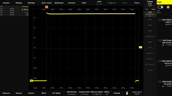
Oszilloskop-Screenshot einer Gleichspannung
Load Quicksave Autoset Clear Auto Normal Triggered Single Force Trigger Edge 1.666 V CH1 Min 0.70% Max 8.10% Avg 2.69% Dev 6.47% +Overshoot Count 128 T -26.5us 23.5us 73.5us 123.5us 173.5us 223.5us 273.5us 323.5us 373.5us 423.5us 473.5us 3.1V 2.6V 2.1V 1.6V 1.1V 600mV 100mV -400mV CH1 500 mV (10:1) DC
in „DSO Batronix Magnova? Erfahrungen?“ · Mechanik, Gehäuse, Werkzeug · · Oszi-Bilder
-
Datei
main.c
delay.h> #include "lcd-routines.h" #define RF_BAUDRATE 15000 // Baudrate des RFM12 unsigned char data[128]; unsigned char tdiv=30; unsigned char lastpins=0; int main(void) { lcd_init(); set_cursor(1,1); lcd_string("Homebedienung "); DDRD=0x00; PORTD=0; DDRC=0xff; PORTC=1; PORTB=1; PORTD=31; DDRC=63; DDRD
in „Frage zu Fuses beim Atmega16“ · Mikrocontroller und Digitale Elektronik ·
-
Datei
noname1.bas
Hard , Interrupt = On , Data Order = Msb , Master = Yes , Polarity = Low , Phase = 0 , Clockrate = 128 Spiinit If Busy = 1 Then 'Wenn Busy Leitung vom Max auf High wechselt Cs = 1 'CS auf Low ziehen Spiout A(1) , 2 'Input Word senden Spiin B(1) , 2 ' Temperaturwert einlesen Else Cs = 0 nop End If Cls
in „MAX 110 in Bascom“ · Mikrocontroller und Digitale Elektronik ·
-
PDF
MAX712_MAX713_MAX.pdf
resistors, and three PART TEMP. RANGE PIN-PACKAGE capacitors are the only required external components. MAX712CPE 0°C to +70°C 16 Plastic DIP For high-power charging requirements, the MAX712/ MAX712CSE 0°C to +70°C 16 Narrow SO MAX713 can be configured as a switch-mode battery MAX712C/D 0°C to +70°C Dice*
in „Akku-/Batteriekapazität messen“ · Mikrocontroller und Digitale Elektronik ·
-
PDF
drv8711.pdf
Maximum Ratings over operating free-air temperature range (unless otherwise noted) (1)(2) (3) MIN MAX UNIT Power supply voltage –0.6 60 V Charge pump voltage (CP1, CP2, VCP) –0.6 12 V 5-V regulator voltage (V5) –0.6 5.5 V Internal regulator voltage (VINT) –0.6 2 V Digital pin voltage (SLEEPn, RESET,
in „UV-Laserdrucker II“ · Platinen ·
-
PDF
xminilab-manual.pdf
+20V AWG Arbitrary Waveform Generator Output range: +/- 2V EXT. T External Trigger Digital input, max 5.5V Logic 0 Digital Channel 0 I2C Sniffer signal: SDA Logic 1 Digital Channel 1 I2C Sniffer signal: SCL Logic 2 Digital Channel 2 UART Sniffer signal: RX Logic 3 Digital Channel 3 UART Sniffer signal
in „USART - xmodem (Xminilab) - Bildübertragung“ · Mikrocontroller und Digitale Elektronik ·
-
PDF
xminilab-manual.pdf
+20V AWG Arbitrary Waveform Generator Output range: +/- 2V EXT. T External Trigger Digital input, max 5.5V Logic 0 Digital Channel 0 I2C Sniffer signal: SDA Logic 1 Digital Channel 1 I2C Sniffer signal: SCL Logic 2 Digital Channel 2 UART Sniffer signal: RX Logic 3 Digital Channel 3 UART Sniffer signal
in „ATXmega32 flashen mit ATMEL Flip (Xminilab)“ · Mikrocontroller und Digitale Elektronik ·
-
PDF
431000.pdf
M M P32GW-50-525A NOTE ITEM MILLIMETERS INCHES Each lead centerline is located within 0.12 A 20.61 MAX. 0.812 MAX. mm (0.005 inch) of its true position (T.P.) at maximum material condition. B 0.78 MAX. 0.031 MAX. C 1.27 (T.P.) 0.050 (T.P.) D 0.40–0.05 0.016–0.003 E 0.15 0.05 0.006 F 2.95 MAX. 0.117 MAX
in „SRAM Ansteuern (Zeitdiagramm)“ · Mikrocontroller und Digitale Elektronik ·
-
PDF
l9805e.pdf
. In this MCU, 63742 of these bytes are user accessible. The available memory locations consist of 128 bytes of I/O registers, 256 bytes of RAM, 128 bytes of EEPROM and 16Kbytes of user EPROM/ROM. The RAM space includes 64 bytes for the stack from 0140h to 017Fh. The highest address bytes contain the
in „ST L9805-E Motortreiber mit H Brücke und ST7UD05 Kern“ · Mikrocontroller und Digitale Elektronik ·
-
PDF
Verbindungsaufbau.pdf
swr4rp_mp3_m.m3u" ETag: "3ada9f66edf9e94e8f012b2f113e7a88" Content-Type: audio/x-mpegurl Cache-Control: max-age=86400 Date: Mon, 10 Aug 2020 11:20:33 GMT Content-Length: 108 Connection: keep-alive #EXTM3U #EXTINF:-1,SWR4 Rheinland-Pfalz http://swr-swr4-rp.cast.addradio.de/swr/swr4/rp/mp3/128/stream.mp3
in „ELV IR100 WEB-Radio kann keine Verbindung mehr aufbauen“ · PC Hard- und Software ·
-
PDF
WM-G-MR-01-v27__01192006.pdf
isolation integration. between BT & WiFi module. l Low power consumption & excellent In addition to WEP 64/128, WPA and TKIP, AES is power management performance, extend supported to provide the latest security requirement battery life. on your network. l 2.412-2.484 GHz two SKUs for worldwide For the software
in „PHILIPS VP5500 VoIP Telefon bei Pollin“ · Mikrocontroller und Digitale Elektronik ·
-
PDF
manual_XT-v.005.pdf
of baud rate selection Example J1/JB1 1 ISelect jumper blockk 2 3 4 jumper installed - 460.8 KBPS max (RS 6 Clock select 230.4 KBPS max (RS 7 Position 7 is not availableed - 115.2 KBPS max on the Xtreme/104 232 Table 2: Baud rates Standard Baud Max. Baud Rate Rate (J1/JB1 jumper)d (J1/JB1 not jumpered
-
PDF
FT2232_datasheet.pdf
FTDI 7 9 FT22 32L D XXYY 0.22+/- 0.05 0.5 1.0 0.24 +/- 0.07 1o +/- 1 2 . 0.09 Min 0.09 Min 0 X / 0.2 Max 0.16 Max 1 M + 1 0.25 0.22 +/- 0.05 0.05 Min 0.2 Min 0.15 Max 0.6 +/- 0.15 The FT2232D is supplied in a 48 pin lead (Pb) free LQFP package. This package has a 7mm x 7mm body (9mm x 9mm including leads
in „AVR-Programmierung via USB mit FT2232“ · Mikrocontroller und Digitale Elektronik ·
-
Datei
mmc_stm32f1.c
xchg_spi(0xFF); /* Diacard following one byte when CMD12 */ n = 10; /* Wait for response (10 bytes max) */ do { res = xchg_spi(0xFF); } while ((res & 0x80) && --n); return res; /* Return received response */ } /*-------------------------------------------------------------------------- Public Functions
in „SD-Karte mit SPI: Warteroutinen“ · Mikrocontroller und Digitale Elektronik ·
-
Datei
mmc_stm32f1.c
xchg_spi(0xFF); /* Diacard following one byte when CMD12 */ n = 10; /* Wait for response (10 bytes max) */ do { res = xchg_spi(0xFF); } while ((res & 0x80) && --n); return res; /* Return received response */ } /*-------------------------------------------------------------------------- Public Functions
in „STM32Fxxx: Frage zur Initialisierung mit der StdPeriphLib“ · Mikrocontroller und Digitale Elektronik ·
-
Datei
diskio.c
xchg_spi(0xFF); /* Diacard following one byte when CMD12 */ n = 10; /* Wait for response (10 bytes max) */ do { res = xchg_spi(0xFF); } while ((res & 0x80) && --n); return res; /* Return received response */ } /*-------------------------------------------------------------------------- Public Functions
in „STm32F103: Beispielcode der Chan FatFs zum Laufen bekommen“ · Mikrocontroller und Digitale Elektronik ·
-
PDF
wama-online-dokumentation-public.pdf
und dabei die ltoa-Funktion nutzen zu können: Der ADC liefert 10bit Werte, die quadriert werden → max. 20bit. ltoa() erwartet signed-Werte → -1bit. Bei einem ausgegebenen Wert pro Sekunde bleibt eine Samplingfrequenz proADC von maximal 2 Hz. Ggf. würde die Prozessorgeschwindigkeit dies weiter limitieren
-
PDF
MatchPort_IntegrationGuide.pdf
g device. Table 2-7. Operating Conditions, Serial Ports, & Configurable Pins Parameter Min Typical Max Units Supply Voltage 3.135 3.3 3.45 V Voltage Ripple 2 % VIL Input Low Voltage* -0.3 0.8 V VIH Input High Voltage* 2 5.5 V II Input Leakage Current* +/- 10 nA +/- µA VOL Output Low Voltage @ IOL max
in „Wlan Modul Spannung“ · Mikrocontroller und Digitale Elektronik ·
-
PDF
datasheet.pdf
Selector Guide S29GL064A, S29GL032A Part Number S29GL064A S29GL032A Speed Option 90 10 11 90 10 11 Max. Access Time (ns) 90 100 110 90 100 110 Max. CE# Access Time (ns) 90 100 110 90 100 110 Max. Page Access Time (ns) 25 30 30 25 30 30 Max. OE# Access Time (ns) 25 30 30 25 30 30 Block Diagram DQ15–DQ0
in „S29GL064A Flash Speicher auslesen“ · Mikrocontroller und Digitale Elektronik ·
-
Datei
LCD_4_45.c
ADC separat aktivieren void starte_adc(void) { ADCSRA = BIT(ADEN) + 0x07; // einschalten mit Teiler /128 } // diverse Initialisierungen void init_interrupts(void) { mach_mal_pause(1); // minimale Zeit sys_timer = 0; // Systemzeit löschen flag_10ms = 0; TCCR0A = BIT(WGM01); // CTC modus max = OCRA OCR0A = T0_MAX_WERT; // ca. 100Hz TCCR0B = 3; // 64 Vorteiler TIFR = BIT(OCIE0A); // flag loeschen TIMSK |= BIT(OCIE0A); // T0-int freigeben starte_adc(); } // für Power-Down T0 und ADC abschalten void sperre_interrupts
in „7-Segm. LCD-Ansteuerung, 4-stelliges Einbaumodul, Attiny45“ · Projekte & Code ·
-
PDF
HP-Displays-HDSP-650x.pdf
2. See electrical sofoperational considerations. 2. Derate linearly above T= 50°C at 2.17mW/OC. PD Max. (TA = 85°C) = 62mW. Electrical/Optical Characteristicsat =, 25OC .-.,,. - - 1/16 Duty Factor NOTES: 3. The luminous intensity ratio between segments within a digisdesigned so that each segment will
in „[V] Intelligente 5*7 Displays, LED 16-Segment-Displays 8-stellig, Ringkerntrafo 15V, 10VA“ · Markt ·
-
PDF
AN721.pdf
conversion factor. A network fulfilling this requirement cannot be obtained For the band-pass filter, Q max or the maximum possible lN in practice as an infinite number of reactive elements would input Q of a device to be matched, has been increased by be necessary. the factor r (from Figure 25, Q′ IN max
in „Stackpole Ferrit Kerne für RF Verstärker“ · HF, Funk und Felder ·
-
PDF
ST_M25P64_data.pdf
from tests performed under the Measure- ters. Table 10. Operating Conditions Symbol Parameter Min. Max. Unit V CC Supply Voltage 2.7 3.6 V TA Ambient Operating Temperature –40 85 °C Table 11. AC Measurement Conditions Symbol Parameter Min. Max. Unit C L Load Capacitance 30 pF Input Rise and Fall Times
-
Datei
main.c
Definition: //#define debug 1 #define counter 1250 #define schaltzeitWeiche 100 #define time 8 #define RAND_MAX 2999 // Höchste Zufallszahl, die bei "rand()" rauskommt // Befehlsdefinition: #define sleep(X) _delay_ms(X) //"_delay_ms() ist einfach nicht so schön zu schreiben wie "sleep()" // Pin Definierung: /
in „Flash Speicher sparen“ · Mikrocontroller und Digitale Elektronik ·
-
 Bild
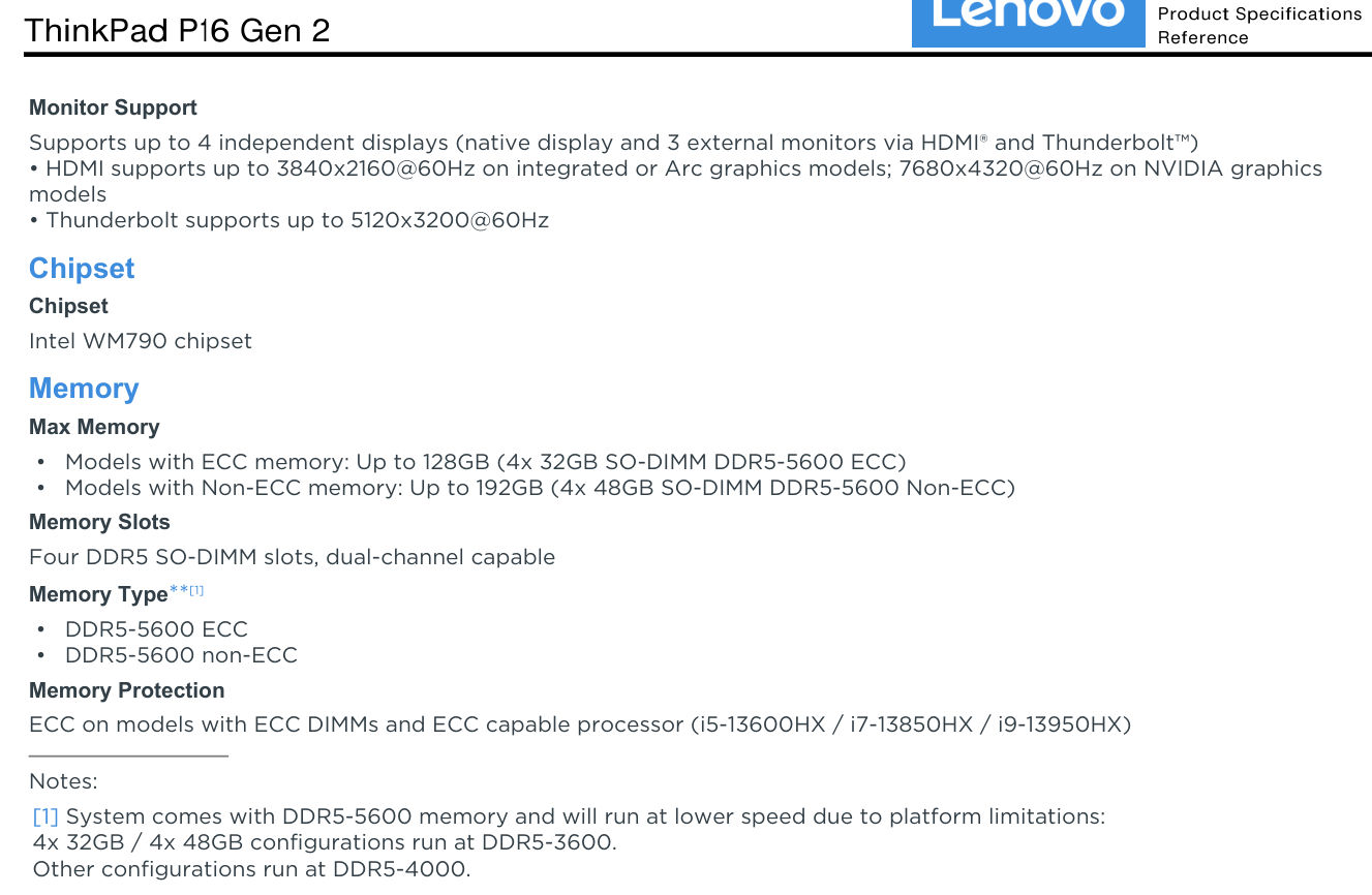
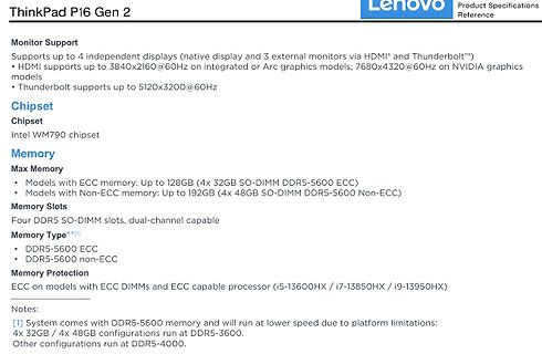
Produktspezifikationen ThinkPad P16 Gen 2
NVIDIA graphics models • Thunderbolt supports up to 5120x3200@60Hz Chipset Intel WM790 chipset Memory Max Memory • Models with ECC memory: Up to 128GB (4x 32GB SO-DIMM DDR5-5600 ECC) • Models with Non-ECC memory: Up to 192GB (4x 48GB SO-DIMM DDR5-5600 Non-ECC) Memory Slots Four DDR5 SO-DIMM slots, dual-channel
in „Lenovo ThinkPad-P16-G2 - RAM erweitern von 64 auf 128 GB“ · PC Hard- und Software · · Screenshots
-
PDF
Anleitung_PowerLog6S_DE.pdf
für bürstenlose Motoren zur Verfügung. x Das Gerät ist mit einem hintergrundbeleuchtetem LC-Display (128 x 64 Bildpunkte), einem Piezosummer und einem USB-Port ausgerüstet. x Der Datenlogger ermöglicht Voreinstellungen für die Spannung der Einzelzellen, die Gesamt- spannung eines Akkus, die Zeit, den Strom
in „TRXCharger Ladekurve mit LogView ansehen“ · Mikrocontroller und Digitale Elektronik ·
-
Datei
Neuron.vhd
11; --Weight Memory Size DATA_WIDTH : integer := 16; --Float16 Format PAGE_WIDTH : integer := 4; --max. 16 Layers INPUT_WIDTH : integer := 7; --max 128 Input Signals INPUTS : integer := 10; --Number of used inputs LATENCY : integer := 6); Port ( --Control Signals clk : in std_logic; reset : in std_logic
in „Pipeline MAC-Unit: Problem mit Latency“ · FPGA, VHDL & Co. ·