-
Datei
main.c
user code ---------------------------------------------------------*/ /* USER CODE BEGIN 0 */ uint16_t ID=0; /* USER CODE END 0 */ /** * @brief The application entry point. * @retval int */ int main(void) { /* USER CODE BEGIN 1 */ /* USER CODE END 1 */ /* MCU Configuration---------------------------
in „4DLCD-32QA mit STM32 initialisieren“ · Mikrocontroller und Digitale Elektronik ·
-
Datei
main_stm32f429.c
float fVal4_test3 = 0.0749; float fVal5_test3 = 0.150; float fVal6_test3; int main(void) { TIM_TimeBaseInitTypeDef TimerInitStruct; GPIO_InitTypeDef GPIOInitStruct; /*----------------------GPIO Konfiguration----------------------*/ RCC_AHB1PeriphClockCmd(RCC_AHB1Periph_GPIOB, ENABLE); GPIOInitStruct.GPIO_Pin
in „XMC4500 vs stm32f429.warum gibt es Unterschiede in der Berechnungsdauer?“ · Mikrocontroller und Digitale Elektronik ·
-
Datei
main.c
define STEP_PORT GPIOA int stepDelay = 1000; // 1000us more delay means less speed void microDelay (uint16_t delay) { __HAL_TIM_SET_COUNTER(&htim1, 0); while (__HAL_TIM_GET_COUNTER(&htim1) < delay); } /* USER CODE END 0 */ /** * @brief The application entry point. * @retval int */ int main(void) { /* USER
in „STM32F401 mit TMC2209 Treiber Nema17 Motor ansteuern“ · Mikrocontroller und Digitale Elektronik ·
-
 Bild
Bild
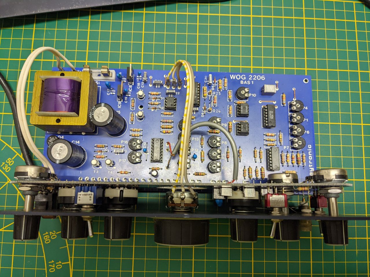
Bestückte Leiterplatte eines Netzteils auf Schneidematte
WOG 2206 BAS 1 C19 C18 C20 R25 CP10 IC91 R24 P9 IC92 P6 P7 P8 P13 P16 P17 T3 C14 T2 C15 C16 C17 C18 C19 C20 C21 C22 C23 C24 C25 C26 C27 C28 C29 C30 C31 C32 C33 C34 C35 C36 C37 C38 C39 C40 C41 C42 C43 C44 C45 C46
in „Tantalkondensatoren am Spannungsregler ersetzen“ · Analoge Elektronik und Schaltungstechnik · · Platinenfotos
-
Datei
Uhr.txt
********* '********* LCD-Konfiguration ********** '************************************** 'LCD als 16x2 Zeichen konfigurieren Config Lcd = 16 * 2 'LCD-Pins konfigurieren Config Lcdpin = Pin , Db4 = Lcd_db4 , Db5 = Lcd_db5 , Db6 = Lcd_db6 , Db7 = Lcd_db7 , E = Lcd_e , Rs = Lcd_rs 'LCD wird im 4-Bit-Modus
in „Bascom Atmega32 startet prog. neu & macht Probleme“ · Mikrocontroller und Digitale Elektronik ·
-
Datei
bm30b.cc
_t scale1 (uint8_t value) { return scale (value, 0, 255); } //using constantRateTimer = AVR::Timer16Bit<1>; //constexpr const auto constantRatePeriod = 1000_us; //struct CTHandler : public IsrBaseHandler<AVR::ISR::Timer<1>::CompareA> { // static void isr() { // ++mCounter; // } // inline static volatile
in „Assembler (AVR) Freaks bitte: der schnellste Weg, einen ganzzahligen Wert zu skalieren?“ · Mikrocontroller und Digitale Elektronik ·
-
Datei
log.txt
phy_addr=0:00, irq=-1) physmap platform flash device: 00800000 at 00000000 physmap-flash.0: Found 1 x16 devices at 0x0 in 16-bit bank Amd/Fujitsu Extended Query Table at 0x0041 number of CFI chips: 1 cfi_cmdset_0002: Disabling erase-suspend-program due to code brokenness. mtd: scanning for physmap-flash
in „Grasshopper Inbetriebnahme“ · Mikrocontroller und Digitale Elektronik ·
-
PDF
84381PSPICESFH6156.pdf
phototransistor optically coupled to a gallium arsenide infrared-emitting diode in 4 pin plastic package. The base terminal of the phototransistor is not connected, resulting in substantially improved common-mode interference immunity. The PSpice models have been written from device characterization data and were tested with simulation program OrCAD16.6. The symbol and model files as well as the netlist are in the symbol library file SFH6156.olb, model library file SFH6156.lib and netlist file SFH6156.txt respectively for this model. This document
in „LTspice Optokoppler SFH6156 verhält sich unplausibel“ · Analoge Elektronik und Schaltungstechnik ·
-
PDF
manual355-ger.pdf
verwenden Sie den Befehl RENAME. Dieser kann über die Kommandozeile eingetippt werden. Beispiel: RENAME DIL16 DIL-16 ; Das Element DIL16 erhält den neuen Namen DIL-16. 55 EAGLE-Handbuch Widerstands-Package Wählen Sie den Package-Editier-Modus, und tragen Sie in das Feld New den Package-Namen R-10 ein. Die Frage
-
Datei
flash_console_out.txt
pli malloc order: 4 +++ ALLOC index: 6160 order: 4 zone: 80849000 page: 80879200(83810000) count: 16 start remap DVR zone 83810000(80879200) 16... total migrated: done: 16 fail: 0 pli malloc order: 7 +++ ALLOC index: 6272 order: 7 zone: 80849000 page: 8087a000(83880000) count: 128 start remap DVR zone
in „Fantec Mediaplayer 3DS4600 zeigt nur noch Startbildschirm“ · Mikrocontroller und Digitale Elektronik ·
-
PDF
IEC_60730_Class_B_and_IEC_61508_SIL_Safety_Software_Library.pdf
to the last flash rows. #define CFG_REGS_CRC_MODE (0u) In this mode, the function calculates a CRC-16 of registers and stores the CRC in flash. Later, function calls recalculate the CRC-16 and compare it with the saved value. It returns a fail if the values are different. 6.16 Startup Configuration Registers
-
PDF
Atmel_8051__Cs.pdf
can only be read. This addressing mode is intended for reading look-up tables in Program Memory. A 16-bit base register (either DPTR or the Program Counter) points to the base of the table, and the Accumulator is set up with the table entry number. The address of the table entry in Program Memory is
in „serielle Ausgaben auf AT89S52 Baud-Raten-Generator startet nicht“ · Mikrocontroller und Digitale Elektronik ·
-
PDF
AD590.pdf
.10 Changesto Figure 17 and Figure 19.........................................10 Rev. G | Page 2 of 16 Data Sheet AD590 SPECIFICATIONS AD590J AND AD590K SPECIFICATIONS 1 25°C andV =S5 V, unlessotherwisenoted. Table 1. AD590J 2 AD590K Parameter Min Typ Max Min Typ Max Unit POWER SUPPLY OperatingVoltage
in „AD590 Temperatursensor von Analog Devices - Frage zum Einbau“ · Analoge Elektronik und Schaltungstechnik ·
-
PDF
ICM7216.pdf
OUTPUT 11 18 VDD SEG fOUTPUT 12 17 DIGIT 6 OUTPUT DIGIT 8 OUTPUT 12 17 SEG b OUTPUT RESET INPUT 13 16 DIGIT 7 OUTPUT RESET INPUT 13 16 SEG c OUTPUT RANGE INPUT 14 15 DIGIT 8 OUTPUT RANGE INPUT 14 15 SEG f OUTPUT ICM7216D COMMON CATHODE (PDIP) TOP VIEW CONTROL INPUT 1 28 INPUT A MEASUREMENT IN PROGRESS
in „[V] 1St. Harris ICM7216AIJI Ceramic DIP28 8-Digit, Multi-Function, Frequency Counters/Timers“ · Markt ·
-
PDF
CD4009-10_TI.pdf
Harris Semiconductor SCHS020C − Revised October 2003 The CD4009UB and CD4010B types are supplied in 16-lead hermetic dual-in-line ceramic packages (F3A suffix), 16-lead dual-in-line plastic packages (E suffix), 16-lead small-outline packages (M, M96, MT, and NSR suffixes), and 16-lead thin shink small-outline
in „Dipl. Ing Heinz Ahborn Orgel - Keine Töne mehr“ · Analoge Elektronik und Schaltungstechnik ·
-
PDF
ISL6753.pdf
RANGE (°C) PACKAGE DWG. # • Buffered Oscillator Sawtooth Output ISL6753AAZA ISL6753AAZ -40 to 105 16 Ld QSOP M16.15A • Internal Over Temperature Protection (See Note) (Pb-free) Add -T suffix to part number for tape and reel packaging • Pb-Free Plus Anneal Available and ELV, WEEE, RoHS Compliant NOTE
in „Warum FET-Ansteuerung mit Trafo?“ · Analoge Elektronik und Schaltungstechnik ·
-
Datei
ch552.pas
interrupt routine bROM_CLK_FAST = $10; // flash-ROM clock frequency selection: 0=normal(for Fosc>=16MHz), 1=fast(for Fosc<16MHz) bRST = $08; // ReadOnly: pin RST input bT2EX_ = $08; // alternate pin for T2EX bCAP2_ = $08; // alternate pin for CAP2 MASK_SYS_CK_SEL = $07; // bit mask of system clock Fsys
in „Turbo51 und CH55x“ · Mikrocontroller und Digitale Elektronik ·
-
PDF
UHF_Remote_Control_System_TEMIC_9606.pdf
16 V L 103 C 8 100 nF, size 1206 air coil 3 turns ∅ 2.5 mm, wire ∅ 0.4 mm, to be tuned C 9 10 µF, 6 V L 104 air coil 3 turns ∅ 2.5 mm, wire C 10a 10 nF ∅ 0.4 mm, length 2.5 mm C 12 150 nF, size 1206 L 105
in „ISM Empfänger mit kleinstem Standby“ · HF, Funk und Felder ·
-
Datei
avr-gcc_8.5.0_relax_MegaCoreX_-v_-Wl-v.txt
Worker\AppData\Local\Temp\arduino_build_961633\core\wiring_pulse.c.o -D__AVR_ATmega4809__ -U__AVR_PM_BASE_ADDRESS__ -D__AVR_PM_BASE_ADDRESS__=0x4000 -D__AVR_DEVICE_NAME__=atmega4809 -D F_CPU=16000000L -D ARDUINO=10819 -D ARDUINO_AVR_ATmega4809 -D ARDUINO_ARCH_MEGAAVR C:\Arduino IDE Portable\megaAVR0\arduino
in „GCC v14 Release“ · Mikrocontroller und Digitale Elektronik ·
-
PDF
an27701.pdf
temperature range is required. The ferrous vane can be made in many configurations, as shown in figure 16. With a linear vane similar to that of figure 16B, it is possible to repeatedly sense position within 0.002 inch over a 125°C temperature range. ELECTRICAL INTERFACE FOR DIGITAL HALL DEVICES The output
in „TLE4935L oder TLE4905L Magnetschalter“ · Analoge Elektronik und Schaltungstechnik ·
-
PDF
an27701.pdf
temperature range is required. The ferrous vane can be made in many configurations, as shown in figure 16. With a linear vane similar to that of figure 16B, it is possible to repeatedly sense position within 0.002 inch over a 125°C temperature range. ELECTRICAL INTERFACE FOR DIGITAL HALL DEVICES The output
in „Schall oder Viberationaufnehmer“ · Mikrocontroller und Digitale Elektronik ·
-
PDF
an27701.pdf
temperature range is required. The ferrous vane can be made in many configurations, as shown in figure 16. With a linear vane similar to that of figure 16B, it is possible to repeatedly sense position within 0.002 inch over a 125°C temperature range. ELECTRICAL INTERFACE FOR DIGITAL HALL DEVICES The output
in „Drehzahlmessung mit Atmega32 über Spannungsteiler an Lichtmaschine“ · Mikrocontroller und Digitale Elektronik ·
-
PDF
an27701.pdf
temperature range is required. The ferrous vane can be made in many configurations, as shown in figure 16. With a linear vane similar to that of figure 16B, it is possible to repeatedly sense position within 0.002 inch over a 125°C temperature range. ELECTRICAL INTERFACE FOR DIGITAL HALL DEVICES The output
in „Drehzahlmessung mit induktivem Näherungsschalter“ · Mikrocontroller und Digitale Elektronik ·
-
PDF
an27701.pdf
temperature range is required. The ferrous vane can be made in many configurations, as shown in figure 16. With a linear vane similar to that of figure 16B, it is possible to repeatedly sense position within 0.002 inch over a 125°C temperature range. ELECTRICAL INTERFACE FOR DIGITAL HALL DEVICES The output
in „Hallsensor als Schalter“ · Mikrocontroller und Digitale Elektronik ·
-
PDF
an27701.pdf
temperature range is required. The ferrous vane can be made in many configurations, as shown in figure 16. With a linear vane similar to that of figure 16B, it is possible to repeatedly sense position within 0.002 inch over a 125°C temperature range. ELECTRICAL INTERFACE FOR DIGITAL HALL DEVICES The output
in „Magnetfeld erfassen mit Hall Sensor“ · Mikrocontroller und Digitale Elektronik ·
-
PDF
an27701.pdf
temperature range is required. The ferrous vane can be made in many configurations, as shown in figure 16. With a linear vane similar to that of figure 16B, it is possible to repeatedly sense position within 0.002 inch over a 125°C temperature range. ELECTRICAL INTERFACE FOR DIGITAL HALL DEVICES The output
in „Brauche Geberrad für Drehwinkelüberwachung“ · Mikrocontroller und Digitale Elektronik ·
-
PDF
142c38eef4c5eb392531e1bacd4aee1b.pdf
TM028HDZ30 V1.0 5.4.3 Interface Register write/read timing I80 8-bit System Bus Interface Timing I80 16-bit System Bus Interface Timing - 14 - Model No.:TM028HDZ30 V1.0 5.4.4 i80-System Interface Data Format a) i80-System Interface with 8-bit Data Bus b)i80-System Interface with 16-bit Data Bus - 15 -
in „Raspberry Pi Rev A TFT Display?“ · Digitale Signalverarbeitung / DSP / Machine Learning ·
-
PDF
GH79L4N_FEB2002_.pdf
.................................................................................................. 16 $PFEC,GPint (in)......................................................................................................................... 17 $PFEC,GPirq (in) .........................................
in „GPS Receiver Furuno / Tecsys GH-79“ · Mikrocontroller und Digitale Elektronik ·
-
Datei
board-omap4panda.c
codec = { .audio = &twl6040_audio, .audpwron_gpio = 127, .naudint_irq = OMAP44XX_IRQ_SYS_2N, .irq_base = TWL6040_CODEC_IRQ_BASE, }; static struct twl4030_platform_data omap4_panda_twldata = { .irq_base = TWL6030_IRQ_BASE, .irq_end = TWL6030_IRQ_END, /* Regulators */ .vmmc = &omap4_panda_vmmc, .vpp =
in „CAN-Interface mit galvanischer Trennung für Pandaboard (OMAP4)“ · Mikrocontroller und Digitale Elektronik ·
-
Datei
SED1520.txt
14745600 $baud = 115200 '-------------------------------------------------------------------- ' SED1520.BAS ' demonstrates the SED1520 based graphical display support '-------------------------------------------------------------------- 'some routines to control the display are in the glcdSED.lib file 'IMPORTANT
in „Grafik LCD Mit SED 1520 Bascom“ · Mikrocontroller und Digitale Elektronik ·
-
Datei
sdram.h
volatile saved_rampz = RAMPZ; RAMPZ = 0; #define _far_mem_exit_ISR() RAMPZ = saved_rampz; #define SDRAM_BASE_ADR 0x000000UL void sdram_init(void); uint8_t sdram_test(uint32_t start, uint32_t size); void sdram_speed_test(uint32_t start_adr, uint16_t size); void sdram_speed_test_dma(uint32_t start_adr, uint16
in „Compilerfehler?“ · Mikrocontroller und Digitale Elektronik ·
-
PDF
ULN2003.pdf
INTEGRATED SUPPRESSION DIODES FOR INDUCTIVE LOADS . OUTPUTS CAN BE PARALLELED FOR HIGHER CURRENT DIP16 . TTL/CMOS/PMOS/DTL COMPATIBLE INPUTS INPUTS PINNED OPPOSITE OUTPUTS TO ORDERING NUMBERS: ULN2001A/2A/3A/4A SIMPLIFY LAYOUT SO16 ORDERING NUMBERS: ULN2001D/2D/3D/4D DESCRIPTION The ULN2001A, ULN2002A
in „Schrittmotor-Treiber Stepper Motor Pacific Scientific Powermax II“ · Mikrocontroller und Digitale Elektronik ·
-
PDF
pb_digiconnectme9210.pdf
seamlessly ties enterprise applications 75MHz and remote devices together. Using Digi Remote Manager, 16MB Mem Power SDRAM Ctrlr Mgmt UART GPIO customers can also easily configure, upgrade, monitor and troubleshoot their device from a centralized location. BENEFITS – Integrated 10/100 Mbit Ethernet interface
in „V] 2St. DIGI-Connect ME Module "Seriell TTL RS232 / LAN Umsetzter"“ · Markt ·
-
PDF
sharp_r733.pdf
état initial lorsque l’appareil est mis en marche. R-733 - 16 DESCRIPTION DU CIRCUIT LSI LSI(IZA855DR) Les signaux E/S du LSI(IZA855DR) sont décrits dans le tableau suivant. No.debroche Signal E/S Description 1-3 SEG21- SORTIE Borneinutilisée. SEG23 4 COM1 SORTIE
in „Fragen zu einem Trafo einer Sharp R733(W) Mikrowelle“ · Analoge Elektronik und Schaltungstechnik ·
-
PDF
sharp_r733.pdf
état initial lorsque l’appareil est mis en marche. R-733 - 16 DESCRIPTION DU CIRCUIT LSI LSI(IZA855DR) Les signaux E/S du LSI(IZA855DR) sont décrits dans le tableau suivant. No.debroche Signal E/S Description 1-3 SEG21- SORTIE Borneinutilisée. SEG23 4 COM1 SORTIE
in „Fragen zu einem Trafo einer Sharp R733(W) Mikrowelle“ · Analoge Elektronik und Schaltungstechnik ·
-
Datei
stm32f429i_discovery_lcd.h
_t *ptr); void LCD_SetDisplayWindow(uint16_t Xpos, uint16_t Ypos, uint16_t Height, uint16_t Width); void LCD_WindowModeDisable(void); void LCD_DrawLine(uint16_t Xpos, uint16_t Ypos, uint16_t Length, uint8_t Direction); void LCD_DrawRect(uint16
in „STM32F429 Display per SPI ansteuern“ · Mikrocontroller und Digitale Elektronik ·
-
Datei
stm32f4_discovery_lcd.h
); void LCD_ClearLine(uint16_t Line); void LCD_Clear(uint16_t Color); void LCD_SetCursor(uint16_t Xpos, uint16_t Ypos); void LCD_DrawChar(uint16_t Xpos, uint16_t Ypos, const uint16_t *c); void LCD_DisplayChar(uint16_t Line, uint16
in „STM32F4Discovery mit CooCox CoOS-RTOS und printf“ · Projekte & Code ·
-
Datei
rc5decode.c
wait max T/2 for H->L transition (middle of next bit) timer = 0; while ( RC5BitHigh() && (timer < 16) ) { WAITFORTIMER(); timer++; } }else{ rc5data &= ~0x00001; // wait max T/2 for L->H transition (middle of next bit) timer = 0; while ( RC5BitLow() && (timer < 16) ) { WAITFORTIMER(); timer++; } } if ( timer == 16 ) { rc5data = 0x0000; // error, next bit not found break; } // wait 3/4 T: await next bit for ( timer=0; timer < 12 ; timer++) WAITFORTIMER(); } }else { rc5data = 0x0000; // error, invalid RC-5 code
-
Datei
TB_Taster_Encoder_V1.bas
.2 bis D.7 ist ein 16*2 LCD angschlossen ' an PortB.0 bis B.3 sind 4 Taster angeschlossen (gegen GND) ' an PortB.4 bis B.5 ist A und B eines Drehencoders angeschlossen (gegen GND) ' an PortC.0 bis C.5 sind 6 LEDs angeschlossen
in „[Bascom-AVR]: Abfrage Panasonic Encoder - aaarrgggh“ · Projekte & Code ·
-
Datei
usart_nrf3.h
//Network command mode OtherNetCmdState = 100, } App_DataPollState; // typedef union { struct { vu16 code; //Number of decimal places and self-test result code vu16 dflt_val; //Regulation protection point vu16 dflt_tim; //Regulation protection action time vu16 rslt_val; //Measured protection point vu16
in „Wechselrichter Hoymiles HM-xxxx 2,4 GhZ Nordic Protokoll?“ · Mikrocontroller und Digitale Elektronik ·
-
PDF
CH572DS1_en.PDF
width channel 1). XXh [31:16] R16_PWM2_DATA RW PWM2 data hold register (16-bit width channel XXXXh 2). [15:0] R16_PWM1_DATA RW PWM1 data hold register (16-bit width channel XXXXh 1). PWM Data Hold Register Group2 (R16_PWM3_DATA)
in „Eagle 7.5 Bibliothek - bitte um Prüfung und Hinweise“ · Platinen ·
-
PDF
i2c.pdf
parameter R with supply voltage as a parameter S P maximum 20 maximum 20 value P value P (k ) (k ) 16 16 12 12 R S 0 VDD = 15V 8 8 10V max. S 5V 4 @ V DD= 5V 4 0 0 2.5V 0 100 200 300 400 0 40 80 120 160 200 bus capacitance (pF) total high level input current ( A) SU00653 SU00654 Figure 27. Maximum value
in „Suche I²C Bus Grundlagen“ · Mikrocontroller und Digitale Elektronik ·
-
Datei
dmxdim.asm
.include "m8def.inc" .def tempL = r16 .def tempH = r17 #define SREGbuf R2 #define DMX_FIELD 0x60 //base address of DMX array; start of SRAM #define DMX_CHANNELS 2 //no. of channels #define DMXstate R18 //status reg for DMX-ISR (r16-r31) #define F_OSC 16000 ; Interrupt Vectors (ATMEGA16 appnote p. 45) .org 0 rjmp init ; Reset Handler reti ; IRQ0 Handler reti ; IRQ1 Handler reti ; Timer2 Compare Handler reti ; Timer2 Overflow Handler reti ; Timer1 Capture Handler reti ; Timer1 CompareA
in „DMX Empfangsproblem mit ATMega16 und Hennes lib @ ASM“ · Mikrocontroller und Digitale Elektronik ·
-
Datei
lib_dmx_in.asm
source ********************** #define USE_DIP //use DIPs for addressing #define DMX_FIELD 0x60 //base address of DMX array #define DMX_CHANNELS 8 //no. of channels #define DMXstate R18 //status reg for DMX-ISR (r16-r31) //X-Pointer reserved for DMX ISR!! #define F_OSC 16000 //oscillator freq. in kHz (typical 8MHz or 16MHz) **************************************************************/ init_dmx: ;**** PortD sbi DDRD, PD0 cbi PortD, PD0 ;enable reception ;**** USART ldi tempL, ((F_OSC/8000)-1) ;set Usart to 250 kbaud
in „DMX-Empfang klappt nicht“ · Mikrocontroller und Digitale Elektronik ·
-
PDF
191095-an-01-de-ROBONOVA-I_BAUSATZ.pdf
MR-C2000-Kontroller: Byte-Port Port 0 Ports #0~#7 (#0 ist ein Port niedriger Ordnung) 1 Ports #8~#16 (#8 ist ein Port niedriger Ordnung) 2 Ports #16~#23 (#16 ist ein Port niedriger Ordnung) 3 Ports #24~#31 (#24 ist ein Port niedriger Ordnung) 4 Ports #32~#39 (#32 ist ein Port niedriger Ordnung) Bei
in „Tubularer Linearmotor“ · Offtopic ·
-
PDF
657982_1.pdf
time.This time is determined In this case, isolation diodes must be used in digit lines to by the time base oscillator and the selected range. For the avoid crosstalk between them (see Figure 14).The direction 10MHz (or 1MHz) time base, the resolutions are 100Hz, of diodes depends on the device version, common
in „Einen Gefallen tun“ · Mikrocontroller und Digitale Elektronik ·
-
Datei
lcd.c
LCD_DB7 DB7 H/L Data bit 7 (MSB) 15 ... BLA ... Backlight anode (+) (with resistor 22 Ohm on +5V) 16 ... BLK ... Backlight cathode (-) (GND) */ // include standard header files #include "avr/io.h" #include "string.h" // include own header files #include "functions.h" #include "config_and_constants.h
in „selbstdefiniertes Zeichen wird am LCD nicht richtig ausgegeben“ · Mikrocontroller und Digitale Elektronik ·
-
PDF
datasheet.pdf
® BTA/BTB16 and T16 Series SNUBBERLESS™ , LOGIC LEVEL & STANDARD 16A TRIAC S MAIN FEATURES: A2 Symbol Value Unit I G T(RMS) 16 A A1 V DRM/VRRM 600, 700 and 800 V A2 GT (Q1) 10 to 50 mA A1 A2 DESCRIPTION Available
in „Kühlkörper für Triac auswählen“ · Analoge Elektronik und Schaltungstechnik ·
-
PDF
BTA_16-600B.pdf
® BTA/BTB16 and T16 Series SNUBBERLESS™ , LOGIC LEVEL & STANDARD 16A TRIAC S MAIN FEATURES: A2 Symbol Value Unit I G T(RMS) 16 A A1 V DRM/VRRM 600 and 800 V A2 GT (Q1) 10 to 50 mA A1 A2 DESCRIPTION Available either
in „BTA 16-600B Triacs“ · Markt ·
-
PDF
cem.pdf
is not actually real. The parasitic capacitances in BJTs are mainly due to the two P{N junctions (base-emitter and base-collector), the depletion-layer capacitances of those P{N junctions being modeled by the same equations and analogous parameters as in the case of diodes. The e®ects of the parasitic
in „Kondensator LT Spice“ · Analoge Elektronik und Schaltungstechnik ·