second pulses, drained every 2 mn at +20 C from atmospheric corrosion undischarged cells with 10 µA base current, yield voltage readings above 3.0 V. The readings may vary according to the pulse characteristics, the Key features temperature, and the cell’s previous history. Fitting the cell with a capacitor
controlled on the default menu. The menu is shown on figure 7. Figure 7: Horizontal Menus 2.1.1 Time Base The time base can be varied from 8µs/div to 50s/div. Table 1 shows all the possible time bases. One time division consists of 16 pixels. Example: 8µs / division = 8µs / 16 pixels ==> 500ns / pixel.
controlled on the default menu. The menu is shown on figure 7. Figure 7: Horizontal Menus 2.1.1 Time Base The time base can be varied from 8µs/div to 50s/div. Table 1 shows all the possible time bases. One time division consists of 16 pixels. Example: 8µs / division = 8µs / 16 pixels ==> 500ns / pixel.
, ADNS-2220 and HLMP ED80- the optimum angle. Features on the lens align it to the XX000. sensor, base plate, and clip with the LED. The lens also Avago Technologies provides an IGES file drawing de- hasalargeroundflangetoprovidealongcreepagepath for any ESD events that occur at the opening of the base
0.3V 5V to V Input Current IN> VDD )...................................50 mA Power Dissipation AT ≤ 70°C) 5-Pin TO-220....................................................1.6W CERDIP.......................................................800 mW DFN............................................ ...........
negative input voltage return. O frequency poles would add enough phase shift to produce Therefore, this base drive current is drawn from the input f oscillations. supply but does not drive the load, so it generates wasted o power that must be dissipated within the LDO regulator: y The FET Advantage PWR (Base Drive) = V INX IBASE o The amount of base current required to drive the PNP is e An LDO regulator can be built using a P-FET as the pass equal to the load current divided by the beta (gain) of the h transistor (see Figure 19). PNP, and beta
negative input voltage return. O frequency poles would add enough phase shift to produce Therefore, this base drive current is drawn from the input f oscillations. supply but does not drive the load, so it generates wasted o power that must be dissipated within the LDO regulator: y The FET Advantage PWR (Base Drive) = V INX IBASE o The amount of base current required to drive the PNP is e An LDO regulator can be built using a P-FET as the pass equal to the load current divided by the beta (gain) of the h transistor (see Figure 19). PNP, and beta
unbefüllten Akkus? Noe. Pollin hat mal vor >10Jahren einen 4V Bleiakku aus Bundeswehr bestaenden der 70er verkauft. Hat problemlos funktioniert nachdem ich da Saeure eingefuellt habe. Der hatte sogar eine eingebaute Plastikkugel welche den Ladezustand angezeigt hat. Vanye
Dafür braucht man keine Schwefelsäure, dafür reicht jede ggf. stärkere Säure oder man könnte auch auf Basen ausweichen, die verursachen genau die gleichen Verätzungen. Oder falls das alles irgendwann verboten ist, reicht heißes Wasser oder Öl, das kann man noch deutlich höher erhitzen. Sowas ist einfach
nur ob ein Selbstbau noch lohnenswert ist. http://www.apc.com/resource/include/techspec_index.cfm?base_sku=BE550%2DGR&total_watts=50 oder ist der Netzbetrieb nur zum Laden der Akkus vorgesehen?
abnimmt. Wenn die Akkus jedesmal komplett entladen werden, erreichen sie nach 200 Zyklen schon nur noch 70% der Kapazität. Bei weniger Entladung entsprechend mehr. Bei Bleiakkus gibt es dazu meist ein Datenblatt, z.B. http://www.vision-batt.com/newpdf/CP/CP6120.pdf Bei LiPo Zellen hab ich bisher kein vergleichbar
glücklicher, vielleicht nicht nur ich... Ach ja, die Schalter- Daten habe ich schonmal gefunden, 2,70€ habe ich hier stehen. Die Verpackung mit Klammern (das die Post hineingucken darf oder muss) und Versand käme dann nochmal auf 1,10 € Immer noch günstiger als die 6,50€ von 'C' denke ich! Also bis
besser wird, allerdings wird durch die Widerstände die Gesamtamplitude an den ADC's geringer (etwa 70%) und somit fällt das Rauschen nicht mehr so auf. Durch die schlechtere Quantisierung wird der Quantisierungsfehler (Quantisierungsrauschen) sogar größer. b) Zur Anpassung an die Widerstände: im
akzeptieren. Roland, antworte mir bitte mal auf folgenden Sachverhalt: Israel hat seid 1948 um die 70 UN Resolutionen misachtet nicht eingerechnet die Zahl der UN-Resolutionen die durch die USA verhindert wurden. Im geleichen Zeitraum hat Israel UN Resulution akzeptietrt die man an den Fingren einer
kaspischen Raum. So ein Mist das Russland dort wieder an Einfluss gewinnt und ein paar von den NATO-Basen die wegen dem Kampf gegen den Terror dort errichtet wurden wieder aufgelöst werden müssen. So wie ich das sehe ist der aktuelle Libanonkonflikt ein weiterer lorischer Schritt im globalen Krieg um
Memory The category is display-only which is determined by POST (Power On Self Test) of the BIOS. Base Memory The POST of the BIOS will determine the amount of base (or conventional) memory installed in the system. The value of the base memory is typically 512 K for systems with 512 K memory installed
from four 3.5V using the single resistor configuration, choose: primary sources: switch I R loss, NPN base drive (AC), NPN base drive (DC), and additional input current. The 3.5V▯1.29V RUVLO1 = 1.29V =190.5k followingformulascanbeusedtoapproximatethepower ▯ ▯ +11.6μ A losses.Theseformulasassumecontinuousmodeopera
regulatory inquiries only.) Alura Group BV P.O. Box 18626 2502 EP The Hague The Netherlands Tel: (31) (0) 70 362-4896 Fax: (31) (0) 70 346-7299 CAUTION: Read and understand this manual before installation and operation of winch. See Safety Precautions. OM-914220-1012-B 4707 N. Mingo Tulsa, Oklahoma 74117 (918
Arcadeautomat: gute Haptik ist wichtig. Mit dem um rund 200 EuR erhältlichen TDK-Micronas Joystick Evaluation Base Kit schickt TDK nun ein Evaluationskit ins Rennen, das die Realisierung eines auf dem HAL3900-Sensor basierenden Joysticks erlaubt. Besonders erwähnenswert ist an dieser Konstruktion, dass das Kit diverse
//www.richis-lab.de/modem01.htm) Wie immer gilt, dass Richard Kaussler das Modul auf mehr als 70 kommentierten Bildern bespricht – ein Klick auf die als Bildquelle genannte URL lohnt sich auf jeden Fall. ### SparkFun: RP2040-Board mit MikroBus-Sockel Wer neue Sensoren ausprobieren möchte
RC1740HP-RC232 433.0525 + n*0.025 MHz RC1740-RC232* n = RF_CHANNEL for n=1 to 69 429.45 for RF_CHANNEL = 70 439.675 + (n-70)*0.025 MHz n = RF_CHANNEL for n=71 to 82 444.000000 MHz for RF_CHANNEL = 83 444.050000 MHz for RF_CHANNEL = 84 444.400000 MHz for RF_CHANNEL = 85 444.450000 MHz for RF_CHANNEL = 86 444.550000
SINK 20 ELECTRICAL CHARACTERISTICS: Unless otherwise stated, these specifications apply for T°C to +70°C for the UC2906 and 0°C to +70°C for the UC3906, +VIN= 10V, TA= TJ. PARAMETER TEST CONDITIONS UC2906 UC3906 UNITS MIN TYP MAX MIN TYP MAX Input Supply Supply Current +VIN= 10V 1.6 2.5 1.6 2.5 mA +VIN
ist der Zeitpunkt der Genehmigung. Danach wird zwar ab und zu nachgerüstet, aber Anlagen aus den 60/70ern wären 20 Jahre später auch mit der erfolgten Nachrüstung nicht mehr genehmigungsfähig gewesen. Man kann also innerhalb der Vorschriften bleiben und trotzdem unvorbereitet sein. Erst recht, wenn man
Nicht nur Flußsäure, sondern so ziemlich das ganze Spektrum an anorganischen Säuren und diverse Basen wurden in verschiedenen Produktionsschritten verwendet. Kreisläufe? Ja, die gibts verschiedentlich auch aber bei Weitem nicht für den ganzen Prozeß. Gruß, Holm
30ETH06S 30ETH06-1 FEATURES • Hyperfast recovery time Low forward voltage drop Low leakage current Base 125 °C operating junction temperature cathode Designed and qualified for industrial level 2 2 DESCRIPTION/APPLICATIONS State of the art hyperfast recovery rectifiers designed with optimized performance
travel_speed*60} ; present print\n{if max_layer_z < max_print_height-10}G1 Z{z_offset+min(max_layer_z+70, max_print_height-10)} F600{endif} ; Move print head further up\nM140 S0 ; turn off heatbed\nM104 S0 ; turn off temperature\nM107 ; turn off fan\nM84 X Y E ; disable motors ensure_vertical_shell_thickness
Bogen noch nicht überspannt ist. Da ist noch mehr drin. Meine Vorschläge: - Netzspannung auf 2016 auf 70Hz, 320V ändern. Dann 2025 auf 85V, 30Hz - Trinkwasser vergällen, hohe Steuern auf Flaschenwasser - Verkürzung des Jahresurlaubs schrittweise auf 15 Tage/Jahr - Neujahr wird ein Arbeitstag (für die
Hauptsache die Kisten haben einen BAS- und Line-Audio-Ausgang. Der Rest interessiert mich nicht. LG old.
-3 shows an actual oscilloscope screen shot, notice how the Hall device supplies one transistor’s base drive signal, and the second transistor’s base is the electrical inverse. This is the waveforms present when the Tiny13 is generating these signals and running the fan at full power. The Tiny13 controls the speed of the fan by pulse width modulating (PWM) these two base drive signals, described below. 2 AVR442 8005A-AVR-09/05 AVR442 Figure 2-3. Oscilloscope photo of fan waveform with 100% drive 2.2 Commutation Controlling the currents or voltages in the motor phases
-3 shows an actual oscilloscope screen shot, notice how the Hall device supplies one transistor’s base drive signal, and the second transistor’s base is the electrical inverse. This is the waveforms present when the Tiny13 is generating these signals and running the fan at full power. The Tiny13 controls the speed of the fan by pulse width modulating (PWM) these two base drive signals, described below. 2 AVR442 8005A-AVR-09/05 AVR442 Figure 2-3. Oscilloscope photo of fan waveform with 100% drive 2.2 Commutation Controlling the currents or voltages in the motor phases
die Möglichkeit sich bei der Fa Schäfer eine Frontplatte fertigen zu lassen, aber die würde bestimmt 70 Euro kosten. Edi M. schrieb im Beitrag #6490888: > Das 120 x 100 passend machen- möglich, aber s ist eben schon... > sportlich. Wie soll das gehen, wenn das Gehäuse innen nur 85 hoch ist? Du
leider auch nicht. Doch, Postscript kann das: num log real returns the common logarithm (base 10) of num. The result is real. EXAMPLE: 10 log ==> 1.0 100 log ==> 2.0 ERRORS: stackunderflow, typecheck, undefinedresult SEE ALSO: ln, exp Ich habe allerdings seit 30 Jahren kein
15:09:28) U-Boot code: 00000000 -> 00011108 data: 000179e8 -> 0004e300 CPU: 140 Mhz HSB: 70 MHz PBA: 35 MHz PBB: 70 MHz malloc: Using memory from 0x11f71000 to 0x11fb1000 DMA: Using memory from 0x11f6d000 to 0x11f71000 Flash: 8 MB at address 0x00000000 DRAM Configuration: Bank
Hallo, bei mir hat geholfen, erst make atngw100-base_defconfig laufen zu lassen und dann erst atngw100_defconfig! Gruß ES
500mA Storage temperature range ________–40°C to +125°C Operating temperature range _______ –20°C to +70°C TOP VIEW Electrical characteristics V = 9,5 to 18V; V = 0V; T = -20 to +70°C unless otherwise specified CC EE amb Parameter Symbol Min. Typ. Max. Unit Supply V CC1and V CC2(pins 14 and 13) Supply current
VS-6CWQ10FNPbF Vishay Semiconductors Schottky Rectifier, 2 x 3.5 A Base FEATURES common cathode • Popular D-PAK outline 4 • Center tap configuration • Small foot print, surface mountable • Low forward voltage drop 2 Common • High frequency operation D-PAK (TO-252AA) cathode
SMBJ) Molding compound meets UL 94 V-0 flammability rating Polarity Uni-directional, bi-directional Base P/N-M3 - halogen-free, RoHS-compliant, and Package DO-214AA (SMBJ) commercial grade Terminals: Matte tin plated leads, solderable per TYPICAL APPLICATIONS J-STD-002 and JESD 22-B102 Use in sensitive
amplifiers using 2N5109 bipolar junction transistors (BJTs). These kinds of amplifiers, known as common base transformer feedback (CBTF) amplifiers, and also known as common base noiseless feedback amplifiers, if properly designed and used, offer MW DXers (and SW DXers, though their needs are not as extreme
durch externe Signale synchronisiert werden. Möglichkeiten: GENLOCK mit FBAS oder Blackburst oder BAS; Netzverkopplung (50 Hz) Achtung: Bei Genlock und Netzverkopplung ist ein Phasenabgleich mit PGE 940 vorzunehmen. Im Hilfemenü sind dazu Abgleichanweisungen vorhanden. Netzteile • Tischnetzteil SN 830I
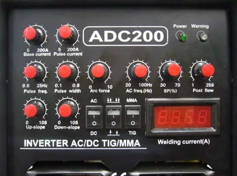
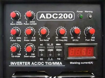
ADC200
Power Warning
5 200A Base current
5 200A Pulse current
0.5 Pulse freq.
0.1 0.9 Pulse width
0 Arc force 10
20 100Hz AC freq.(Hz)
30 70 SP(%)
1 25S Post flow
0 10S Up-slope
0 10S Down-slope
AC MMA
DC TIG
8.8.8.8
Welding current
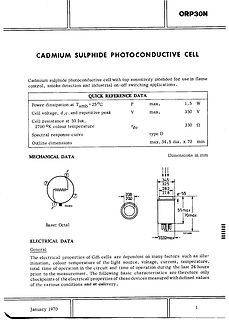
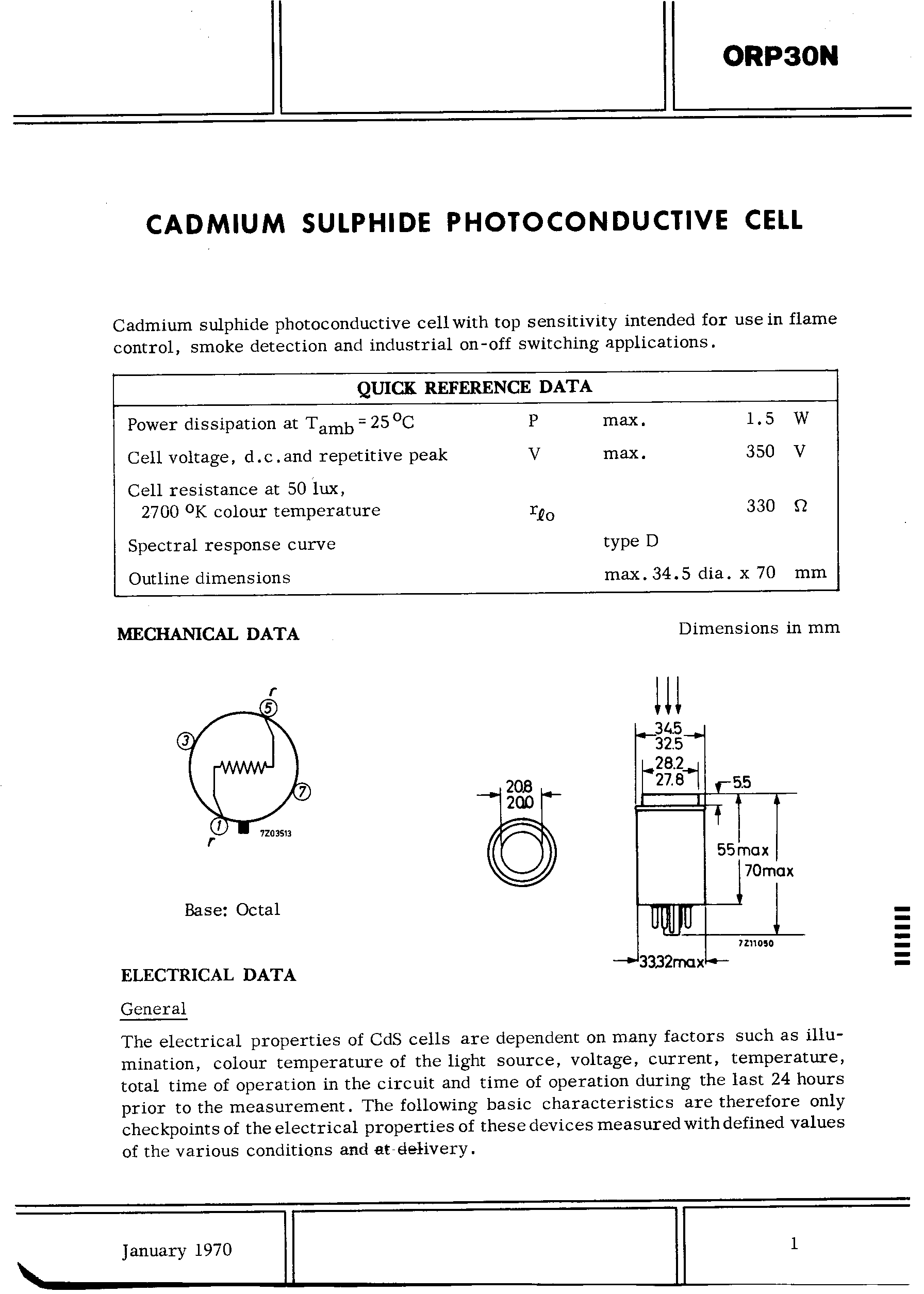
30 Ω
270 °K colour temperature
type D
Spectral response curve
Outline dimensions max. 34.5 dia. x 70 mm
MECHANICAL DATA Dimensions in mm
Base: Octal
ELECTRICAL DATA
January 1970
logf(float x) returns the natural logarithm of x. float log10f(float x) returns the base-10 logarithm of x. float modff(float x, float *pint) returns a fraction f and stores an integer into *pint that represents x. f + (*pint) equal x. abs(f) is in the interval [0, 1) and both
Wir versuchen mal bis 70 kHz zu kommen.... die 100 KHz wären wirklich Obergrenze!
Vorab: Test in der Konsole... C:\Users\Privat>cargo --version cargo 1.70.0 (ec8a8a0ca 2023-04-25) C:\Users\Privat> C:\Users\Privat>clang --version clang version 16.0.0 Target: x86_64-pc-windows-msvc Thread model: posix InstalledDir: C:\Program Files\LLVM\bin
- Enable four-operand fused multiple-add. fsgsbase - Support FS/GS Base instructions. fsrm - REP MOVSB of short lengths is faster. harden-sls-ijmp - Harden against straight line speculation across indirect JMP instructions
Current G 3 l Max I GT of 50 mA (Quadrants 1 - 3) Pin 2 is in electrical contact with the mounting base. MDC2ACA absolute maximum ratings over operating case temperature (unless otherwise noted) RATING SYMBOL VALUE UNIT TIC246D 400 TIC246M 600 Repetitive peak off-state voltage (see Note 1) TIC246S VDRM 700 V TIC246N 800 Full-cycle RMS on-state current at (or below) 70°C case temperature (see Note 2) T(RMS) 16 A Peak on-state surge current full-sine-wave at (or below) 25°C case temperature (see Note 3) ITSM 125 A Peak gate current IGM ±1 A Operating case temperature
Current G 3 l Max I GT of 50 mA (Quadrants 1 - 3) Pin 2 is in electrical contact with the mounting base. MDC2ACA absolute maximum ratings over operating case temperature (unless otherwise noted) RATING SYMBOL VALUE UNIT TIC246D 400 TIC246M 600 Repetitive peak off-state voltage (see Note 1) TIC246S VDRM 700 V TIC246N 800 Full-cycle RMS on-state current at (or below) 70°C case temperature (see Note 2) T(RMS) 16 A Peak on-state surge current full-sine-wave at (or below) 25°C case temperature (see Note 3) ITSM 125 A Peak gate current IGM ±1 A Operating case temperature

 Bild
Bild
 Bild
Bild
 Bild
Bild
 Bild
Bild