
-
PDF
DEM240128BFYH-LY.PDF
DISPLAYELEKTRONIK GMBH CONTENTS LCD MODULE DEM 240128B FYH-L Y Product specificaVersion : 3 20/Jan/2004 GENERAL SPECIFICATION MODULE NO. : DEM 240128B FYH-L Y CUSTOMER P/N VERSION NO. CHANGE DESCRIPTION DATE 0 ORIGINAL VERSION 2002/03/29 1 ADD PCB DRAWING 2002
in „glcd DEM240128B mit S6B2086X1 Controller (240x128px), wie ansteuern?“ · Mikrocontroller und Digitale Elektronik ·
-
 Bild
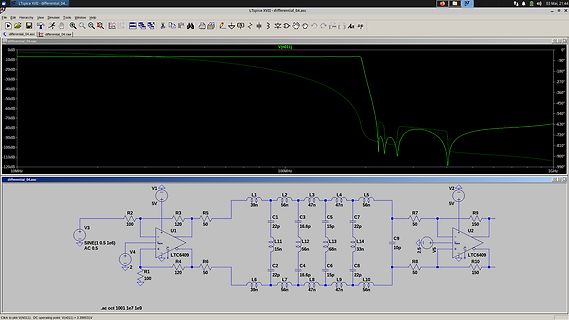
LTspice Schaltplan und Frequenzgang-Diagramm
LTspice XVII - differential_04.asc 03 Mai, 21:44 V(n011) 0dB -180° -270° -360° -450° -540° -630° -720° -810° -900° -990° 10MHz 100MHz 1G V1 5V V2 5V V3 SINE (0.5 1e6) AC 0.5 V4 2 R1 100 R2 100 R3 120 R4 120 R5 50 R6 120 R7 50 R8 50 R9 150 R10 150 L1 39n L2 56n L3 47n L4 47n L5 56n L6 39n L8 47n L9 33n L10 56n L11 15n L12 56n L13 68n L14 33n C1 22p C2 22p C3 16.6p C4 16.6p C5 22p C7 22p C9 10p U1 LTC6409 U2 LTC6409 .ac oct 1001 1e7 1e9
in „DDS, Filteranpassung ohne Transformator“ · Analoge Elektronik und Schaltungstechnik · · Screenshots
-
PDF
Abbildungsverzeichnis_-_Que.pdf
Abbildungsverzeichnis - Querverweis - Probleme - www.Office-L... http://www.office-loesung.de/ftopic70000_0_0_asc.php Office Telefon / Excel Hotline Office Forum Experten des Forums im Dialog Rahmenzeit: Montag bis Freitag 10:00 - 20:00 www.Office-Loesung.de Hier
-
Datei
teststk_mega16.c
0x00; //unsigned char PORTB = 0x00; //clear pullups DDRB = 0x00; //PORTB is input while( (temp & 0x03) != 0x03 ) //upper 6 bits 'cleared' and compared with 0b00000011 { PORTD = 0b11111101; //RD enabled, 'command' selected // asm volatile ("nop"::); // asm volatile ("nop"::); PORTD = 0b11111001; //CS
in „LCD an T6963C und ATMega323“ · Mikrocontroller und Digitale Elektronik ·
-
PDF
Option_LAN.pdf
1 2 3 4 5 6 Option LAN Würth 742792038 +3.3D L21_10 PIL210101 PIL210102 10 A CO21_1 U21_10 A 10100n LA_CLK25 PIU21OUT GND PIU210102 GND 03 0 0 R21_103 2 R21_10 PIU21VDD4 E/D PIU210101 49R9 O12 R 10R GND 03 R 0 4 0 Würth 742792038 25MHz +3.3D L21_
in „TEKWAY DST1xx2B Oszilloskop“ · Mikrocontroller und Digitale Elektronik ·
-
PDF
NA-Zertifikat_WVC-600.pdf
9K@0G06AN ▯▯$.5BAGNGG49▯N▯640;G06AN/0@N▯B>>09@.5+9A0?@▯N/+?1N▯ N:@N;6.5ANL-0?@.5?06A0;▯N ▯60NI-0?>?L1B;4N/0?N▯0@+:AD6?8B;4@80AA0NM ▯▯$.5BAGN▯ ▯B>>09@.5+9A0?▯N1L5?A0NGBN06;0?N0?3<94?06.50;N▯-@.5+9AB;4▯N ▯0?N<-0;N40;+;;A0N ▯▯$.5BAGN5+AN:6AN/0;NGB40<?/;0A0;N▯?G0B4B;4@06;506A0;N/60N▯;1 ?/0?B;40;NGB?N▯;@09;0AG0?80;;B;4N:6AN ▯6910N/0@N+8A6C0;N'0?1+5?0;@N▯$.5D6;48?06@A0@A▯N0?1L99A▯N ▯0?N<-0;N40;+;;A0N ▯▯$.5BAHN0?1L99AN/60N▯;2 =?/0?B;40;NHB?N$F;.5?<;6@+A6<;▯N $06A0N▯NC<;N▯N
in „Mikrowechselrichter WVC Zertifikate“ · Haus & Smart Home ·
-
PDF
Tyco-PCN.pdf
voltage resistance power VDC VDC VDC Ω±10% mW Rated current 3A/5A Limiting continuous current 3A/5A 03 3 2.1 0.3 75 120 Breaking capacity max. 750VA (3A), 1250VA(5A) 04 4.5 3.15 0.45 169 120 Contact material AgNi, gold plated 05 5 3.5 0.5 208 120 Contact style bifurcated contact 06 6 4.2 0.6 300 120 Min
in „64 Stück PNC Relais gleichzeitig in schalten“ · Mikrocontroller und Digitale Elektronik ·
-
PDF
LT1006.pdf
/ / O ( T = 25°C ( V I A I E1.0 G1M G 1M TA= 125°C S E E O A A I L TA= 125°C L E V V N0.5 H C LT1006 METAL CAN (H) PACKAGE LT1006 CERDIP (J) PACKAGE 0 100k 100k 0 1 2 3 4 100 1k 10k 100 1k 10k TIME AFTER POWER ON (MIN) LOAD RESISTANCE TO GROUND (Ω) LOAD RESISTANCE TO
in „Probleme mit Peakdetector“ · Mikrocontroller und Digitale Elektronik ·
-
Datei
NHD_2_7.ino
0x01, 0x60, 0xF0, 0x00, 0x00, 0x00, 0x00, 0x1F, 0x80, 0x00, 0x00, 0x30, 0xCC, 0x3F, 0x0E, 0xC3, 0x03, 0x20, 0xE0, 0x00, 0x00, 0x00, 0x00, 0x07, 0x00, 0x00, 0x00, 0x30, 0xCC, 0x03, 0x8F, 0xC3, 0x03, 0xF0, 0x60, 0x00, 0x00, 0x00, 0x00, 0x00, 0x00, 0x00, 0x00, 0x3F, 0x8C, 0x3F, 0x8C, 0x03, 0x07, 0xF0,
in „NHD-2.7-12864WDW3 mit SSD1322 - Grayscale Problem“ · Mikrocontroller und Digitale Elektronik ·
-
PDF
RealSimGear.pdf
01h code:00ef.1 01 ?? 01h code:00f0 01 ?? 01h code:00f0.1 01 ?? 01h code:00f1 01 ?? 01h code:00f1.1 03 ?? 03h code:00f2 03 ?? 03h code:00f2.1 03 ?? 03h code:00f3 03 ?? 03h code:00f3.1 03 ?? 03h code:00f4 03 ?? 03h code:00f4.1 03 ?? 03h code:00f5 03 ?? 03h code:00f5.1 04 ?? 04h code:00f6 07 ?? 07h code
in „ATmega2560 hex File disassemblieren“ · Mikrocontroller und Digitale Elektronik ·
-
PDF
SEMIKRON_DataSheet_SKT_100_01236311.pdf
10 Nm M12 or ½” - 20 UNF (lubricated)1) 7,5 Nm a 5 * 9,81 m/s2 m approx. 100 g Case B5 SKT 1 2020-03-25 RP © by SEMIKRON SKT 100 Fig. 1L Power dissipation vs. on-state current Fig. 1R Power dissipation vs. ambient temperature Fig. 2 Rated on-state current vs. case temperature Fig. 3 Recovered charge
in „Thyristor Steuerung mit Teensy 4.0“ · Analoge Elektronik und Schaltungstechnik ·
-
PDF
ec_motor.pdf
Schaltern gebildet, die entweder geschlossen oder geöffnet sind. ☺ Weber Tony, ☺ Ramagnano Nicola 25.03.2004 Berufsschule Uster EC – Motor Elektrotechnik Seite 2/5 Wenn wir also einen Voll-Zyklus mit 360° ansetzen, dann führt jeder der drei Ausgänge abwechselnd für eine Drittelumdrehung (120°) Plus, während
in „Brushless DC Motor: 12 Spulen / 14 Magente ?“ · Analoge Elektronik und Schaltungstechnik ·
-
Datei
Master.asm
DATA_TO_SEND, X+ ORI DATA_TO_SEND, SEND_BLUE RCALL SEND_DATA //Auf vollständige Übertragung warten UPDATE_SLA03: SBIS SPSR, SPIF RJMP UPDATE_SLA03 SBI PORTB, SLAVE_3 END_UPDATE_SLAVES: RET //////////////////////////////////////////////////////////////////////////////////////////////// // Sendet das Byte DATA_TO_SEND
in „SPI Fehlererkennung/-korrektur“ · Mikrocontroller und Digitale Elektronik ·
-
Datei
UART.c
RX_DDR &=~(1<<RX_Pin); //definiere RX Pin als Eingang UBRR0H = 0b00000000; // Setzt Baudrate //UBRR0L = 0b00110011; // dezimal : 103->9600; dez 68->14400;dez 51->19200; dez 8 ->115200 //UBRR0L = 0b00011001; //38400 //UBRR0L = 0b00000011; //230400 //UBRR0L = 0b11001111; //9600 UBRR0L = 0b00010000; //115200
in „Brauche Unterstützung beim OV7670 (bzw. SCCB)“ · Mikrocontroller und Digitale Elektronik ·
-
Datei
UART.c
RX_DDR &=~(1<<RX_Pin); //definiere RX Pin als Eingang UBRR0H = 0b00000000; // Setzt Baudrate //UBRR0L = 0b00110011; // dezimal : 103->9600; dez 68->14400;dez 51->19200; dez 8 ->115200 //UBRR0L = 0b00011001; //38400 //UBRR0L = 0b00000011; //230400 //UBRR0L = 0b11001111; //9600 UBRR0L = 0b00010000; //115200
in „Brauche Unterstützung beim OV7670 (bzw. SCCB)“ · Mikrocontroller und Digitale Elektronik ·
-
PDF
D130858D.PDF
Saturation Voltage vs. Collector Current vs. Collector Current e )0 )10 t ( IC / B = 4 g ( IC / IB= 4 o t5 l ) 5 V s V a o E n ( a C2 75 °C t B u V r V 2 a 1 t Tc = –25°C r 25 °C S 1 t 0.5 e i i E m 0.5 25 °C 75 °C t 0.2 E o t c s 0.2 l 0.1 Tc = –25 °C B o C 0.05 0.1 0.2 0.5 1 2 5 10 20 0.1 0.2 0.5 1 2 5 10
in „Transistor am Arduino“ · Mikrocontroller und Digitale Elektronik ·
-
PDF
ep-2001-09-720-722.pdf
alten Bundes- Stromkreise xx ländern [2]. In den VDE-Bestimmungen 0100:1973-05 [3] heißt es dazu: L1 L2L3 N PEN oder PE noch nicht Wohnungsverteiler WV umgestellt! „Die Nullung wird hergestellt durch das Anschließen der Körper L • bei Leitungsquerschnitten unter 10 mm 2 Cu über einen besonderen Schutzleiter
-
PDF
Timer_Register_ATmega8_und_ATmega88.pdf
0x00FF TOP BOTTOM 2 0010 PWM, phase correct 9 bit 0x01FF TOP BOTTOM 3 0011 PWM, phase correct 10 bit 0x03FF TOP BOTTOM 4 0100 CTC OCRA Immediate MAX 5 0101 Fast PWM 8 bit 0x00FF BOTTOM TOP 6 0110 Fast PWM 9 bit 0x01FF BOTTOM TOP 7 0111 Fast PWM 10 bit 0x03FF BOTTOM TOP 8 1000 PWM, Phase an Frequency Correct
in „ATmega88 Timer mit Interrupt“ · Mikrocontroller und Digitale Elektronik ·
-
Datei
iom16.h
CS22 2 #define WGM21 3 #define COM20 4 #define COM21 5 #define WGM20 6 #define FOC2 7 /* Combine ICR1L and ICR1H */ #define ICR1 _SFR_IO16(0x26) #define ICR1L _SFR_IO8(0x26) #define ICR1H _SFR_IO8(0x27) /* Combine OCR1BL and OCR1BH */ #define OCR1B _SFR_IO16(0x28) #define OCR1BL _SFR_IO8(0x28) #define
in „ATMega16 mehrere Taster an INT0“ · Mikrocontroller und Digitale Elektronik ·
-
PDF
Display_Controller.pdf
as shown in Table 1. Table 1 Parallel / Serial Interface Mode Type PS2 PS1 PS0 CSB Interface mode L H 6800-series MPU mode Parallel H CSB L L 8080-series MPU mode L L L CSB 3-Line SPI mode Serial L H L CSB 4-Line SPI mode H L L CSB IIC SPI mode Parallel Interface (PS0 = "H") The 8-bit bi-directional
in „LCD Controler mit Spannungsregulier-Eingängen“ · Mikrocontroller und Digitale Elektronik ·
-
Datei
t6963c_main_v3.asm
64 .equ TXT_ZEILEN = 64/8 ;=============================================== ;= Pinbelegung Display (L = low-active) = ;=============================================== .equ wr = PB0 ; Data Write (L) .equ rd = PB1 ; Read Data (L) .equ ce = PB2 ; chip enable (L) .equ cd = PB3 ; Command/Data (H/L) .equ reset
in „Optimierung ASM-Code für GLCD“ · Mikrocontroller und Digitale Elektronik ·
-
Datei
foo.dwarf-3.txt
.long .LASF937 .byte 0x4 .file 12 "e:\\winavr\\4.8_2013-03-06\\avr\\include\\avr\\io.h" .byte 0x3 .uleb128 0x7 .uleb128 0xc .byte 0x5 .uleb128 0x61 .long .LASF938 .file 13 "e:\\winavr\\4.8_2013-03-06\\avr\\include\\avr\\sfr_defs.h" .byte 0x3 .uleb128 0x63 .uleb128 0xd .byte 0x7 .long .Ldebug_macro13 .byte 0x4 .file 14 "e:\\winavr\\4.8_2013-03-06\\avr\\include\\avr\\iom168.h" .byte 0x3 .uleb128 0xfe .uleb128 0xe .byte 0x5 .uleb128 0x22 .long .LASF963 .file 15 "e:\\winavr\\4.8_2013-03-06\\avr\\include\\avr\\iomx8.h" .byte 0x3 .uleb128 0x24
in „Simple C Frage zum Typ enum“ · Mikrocontroller und Digitale Elektronik ·
-
Datei
main.c
(Disabled) #pragma config CPD = OFF // Data EE Read Protect (Disabled) // CONFIG6L #pragma config WRT0 = OFF // Table Write Protect 00800-03FFF (Disabled) #pragma config WRT1 = OFF // Table Write Protect 04000-07FFF (Disabled) #pragma config WRT2 = OFF // Table Write Protect 08000-
in „PIC18F25k80 Probleme mit dem ADC“ · Mikrocontroller und Digitale Elektronik ·
-
PDF
LM340.pdf
Power Package (T) 00778111 00778112 Bottom View Top View See Package Number K02A See Package Number T03B TO-263 Surface-Mount Package (S) 3-Lead SOT-223 00778120 00778143 Top View Top View See Package Number TS3B See Package Number MP04A www.national.com 2 L M 3 Absolute Maximum Ratings (Note 1) TO-220
in „Suche Schaltung für Spannungsverdoppler von 12V auf 24V“ · Analoge Elektronik und Schaltungstechnik ·
-
PDF
295012fd-2954584.pdf
, Enable (PB, EN/EN) V PB(MIN, MAX) PB Voltage Range Single-Ended l –1 26.4 V IPB PB Input Current 2.5V < VPB< 26.4V l ±1 µA VPB = 1V l –1 –6 –12 µA VPB = 0.6V l –3 –9 –15 µA V PB(VTH) PB Input Threshold PB Falling l 0.6 0.8 1 V V PB Open Circuit Voltage I = –1µA 1 1.6
in „[V] 5St. Push Button On/Off Controller LTC2950 (9€)“ · Markt ·
-
PDF
295012fd-2954584.pdf
, Enable (PB, EN/EN) V PB(MIN, MAX) PB Voltage Range Single-Ended l –1 26.4 V IPB PB Input Current 2.5V < VPB< 26.4V l ±1 µA VPB = 1V l –1 –6 –12 µA VPB = 0.6V l –3 –9 –15 µA V PB(VTH) PB Input Threshold PB Falling l 0.6 0.8 1 V V PB Open Circuit Voltage I = –1µA 1 1.6
in „[V] 3St. Push Button On/Off Controller LTC2950 (7€)“ · Markt ·
-
Datei
HD44780_mod.h
buff; static const value_t EXP10_TABLE[] PROGMEM = //******************************************* { 10L, 100L, 1000L, 10000L, 100000L, 1000000L, 10000000L, 100000000L, 1000000000L }; #define VALOUT_DECIMAL_POINT '.' #define PROGMEM_TABLE_SIZE ( sizeof(EXP10_TABLE) / sizeof(value_t) ) //****************
in „Welchen Controller für C++ Programmierung?“ · Mikrocontroller und Digitale Elektronik ·
-
PDF
0900766b80c5a119.pdf
005 44 413 11 LT K Chisel tip long, packaged 100pcs.1,2 mm 0,4 mm 21,0 mm 360,00 005 44 414 00 LT L Chisel tip long, bulk 2,0 mm 1,0 mm 21,0 mm 3,95 005 44 414 11 LT L Chisel tip long, packaged 100pcs.2,0 mm 1,0 mm 21,0 mm 360,00 005 44 415 00 LT M Chisel tip long, bulk 3,2 mm 1,2 mm 21,0 mm 3,95 005
in „Flussmittel-Paste oder Flüssigkeit zum SMD-Löten“ · Platinen ·
-
PDF
at-240160bx1.pdf
. 8 8 INTERFACE DEFINITION CN1: Interface of pure driver PIN NO. SIGNAL LEVEL FUNCTION 1~4 D0~D3 H/L Data Input(4 bits) 5 /DISPOFF H/L H: Display ON(default)L: Display OFF 6 FLM H/L First Line Marker No Connection (M signal input while not built-in 7 NC (M) -- M signal circuit) 8 LP H/L Data Latch Signal
in „Kennt jemand das Teil?“ · Mikrocontroller und Digitale Elektronik ·
-
PDF
IRF1404.pdf
PD-91896F IRF1404 ® HEXFET Power MOSFET l Advanced Process Technology l Ultra Low On-Resistance D l Dynamic dv/dt Rating VDSS = 40V l 175°C Operating Temperature l Fast Switching R = 0.004Ω l Fully Avalanche Rated G DS(on) l Automotive Qualified
in „MOSFET wird sehr heiß“ · Analoge Elektronik und Schaltungstechnik ·
-
Datei
lcd_driver_ks0073.c
www.opendcc.de // history: 2008-09-18 V0.01 jmf started // 2009-01-13 V0.02 kw comments, tests // 2009-01-26 V0.03 kw set_cursor jetzt ab 0,0 // 2009-03-07 V0.04 kw get_cursor neu dazu // 2009-03-20 V0.05 kw nach init cursor off // 2009-03-27 V0.06 kw #if DISPLAY added // 2009-04-04 V0.07 kw cursor_on_at added //
in „EA DIP204-4 Datenblatt verständnis“ · Mikrocontroller und Digitale Elektronik ·
-
Datei
rtc_calendar.S
log ; ;1.0 - Inital version - L.Westlund ;****************************************************************************** ;Variables ; .def TI_day ; .def TI_FebDays ; .def TI_hour ; .def TI_dayOfWeek ; .def TI_PM ; .def TI_second ;
in „msp430gcc4 / Eclipse / Sampel code MSP430F499stk2“ · Mikrocontroller und Digitale Elektronik ·
-
PDF
STB10NK60Z.pdf
0.067 F2 1.15 1.7 0.045 0.067 G 4.95 5.2 0.195 0.204 G1 2.4 2.7 0.094 0.106 H 10 10.4 0.393 0.409 L2 16 0.630 L3 28.6 30.6 1.126 1.204 L4 9.8 10.6 .0385 0.417 L5 2.9 3.6 0.114 0.141 L6 15.9 16.4 0.626 0.645 L7 9 9.3 0.354 0.366 Ø 3 3.2 0.118 0.126 E A D B L3 L6 L7 F F 1 G H G F 1 2 3 L5 L2 L4 11/19
in „Ersatz für STB10NK60Z“ · Mikrocontroller und Digitale Elektronik ·
-
PDF
cd0603-b.pdf
YLNHYKPUN▯[OL▯HTV\U[▯VM▯HKKP[PVUHS▯[LZ[▯THYNPU▯[V▯KLZPNU▯PU[V▯[OLPY▯KL]PJL▯VY▯HWWSPJH[PVU▯[V▯JVTWLUZH[L▯MVY▯ KPɈLYLUJLZ▯IL[^LLU▯SHIVYH[VY`▯HUK▯YLHS▯^VYSK▯JVUKP[PVUZ▯ <USLZZ▯)V\YUZ▯OHZ▯L_WSPJP[S`▯KLZPNUH[LK▯HU▯PUKP]PK\HS▯)V\YUZ ® product as meeting the requirements of a particular industry Z[HUKHYK▯▯L▯N
in „Fein MultiTalent AFMT 12 QSL - Bauteil identifizieren“ · Mechanik, Gehäuse, Werkzeug ·
-
PDF
MB91F465DA-FujitsuMediaDevices.pdf
8 8 8 8 8 8 8 8 9 9 9 9 91 1 1 1 19 5 QY 0 1 2 3 6 7XX X O K EK 5 2 1 0X A A1 0 5 5C R R 0 1 2 32 L3 L T 0T 1 0 2 2 34 L 00 2 5 S BR S S S S S S/A W L C LC S D D DN X XX X D S1 D D I I I ID CD C I /I / T / T TT C ABI/ D V 67 0 1 2 3 6 7_/ 3 C / MO V MMM I V VC V V 0 1 2 3/ 5/ 7 0 _1 _ / _ / // 5 22
in „LCD Display / Controller eines Schweißgerätes prüfen“ · Mikrocontroller und Digitale Elektronik ·
-
Datei
Melodieklingel-48.bas
&H20 , &HB3 ' -- Titel #13 ---------------------------------------------------------------- Data &H03 , &H00 , &H03 , &H00 , &H25 , &H00 , &H23 , &H00 , &H28 , &H00 , &H47 Data &H20 , &H03 , &H00 , &H03 , &H00 , &H25 , &H00 , &H23 , &H00 , &H2A , &H00 Data &HC8 ' -- Titel #14 ------------------------
-
Datei
Wie_archiviert_ihr_Websites__-_Mikrocontroller.net.html
PLQp9+X16+5KgSSTyt+9NzkbpMnrpHVqLKXawaONLkXSC3OdTW0PHh1Y0LqArkeP+jvOnlp0fuJdUHd+zAhx4rKPjNjjdbwliiXued7L2jL9jPXELSBiOvXshQ8okg/j4udV9ANVlHaVTC6BbCl+PRJRu40DYAwF50lHTfUsL+z0DehjAP7/s6L5TQdX+yIAi/MXnHWMGENHbNksKulDdEwl1dUCe2vItHDzWkz14tyfeSZ/R1G46T2Yh1IXZJh9KSPTzrQExcCRoHfQUOxbQUoyKc6pOQS627nPLyuRskQ3Ipm+
-
PDF
INA102.pdf
Signal, ±1% Flatness V = 0.1Vrms OUT G = 1 30 * * kHz G = 10 3 * * kHz G = 100 0.3 * * kHz G = 1000 0.03 * * kHz Full Power, G = 1 to 100 VOUT = 10V, RL= 10k 1.7 2.5 * * * * kHz Slew Rate, G = 1 to 100 VOUT = 10V, RL= 10k 0.1 0.15 * * * * V/ s Settling Time R = 10k , C = 100pF L L 0.1%: G = 1 10V Step 50
in „Pulsmessung und Anzeige der Pulswelle auf einem LCD Display“ · Mikrocontroller und Digitale Elektronik ·
-
PDF
doc5131.pdf
At that time CLKM is turned off. If the CLKM output is turned off (bits CLKM_CTRL = 0 in register 0x03), the SLEEP state is entered immediately. 22 AT86RF230 5131E-MCU Wireless-02/09 AT86RF230 Setting SLP_TR = L returns the radio transceiver to the TRX_OFF state. It is recommended that pin SLP_TR should
-
PDF
LT3092fb.pdf
l –0.5 –2 mV OS LOAD Line Regulation ΔISET ΔVIN 2V to 40V, ILOAD = 1mA 0.03 0.2 nA/V ΔV OS ΔVIN = 2V to 40V,LOAD = 1mA 0.003 0.010 mV/V MinimumLoad Current (Note 3) 2V ≤ VIN≤ 40V l 300 500 μA Dropout Voltage
in „Konstantstromquelle LT3092 - Widerstandswahl“ · Analoge Elektronik und Schaltungstechnik ·
-
Datei
bin_fw_files_headers.txt
---------------- 0 0x0 uImage header, header size: 64 bytes, header CRC: 0x54ED5B50, created: 2010-03-25 18:03:23, image size: 6648814 bytes, Data Address: 0x0, Entry Point: 0x0, data CRC: 0xF9AA6411, OS: Linux, CPU: PowerPC, image type: RAMDisk Image, compression type: gzip, image name: "Ramdisk Tar Image" 64 0x40 gzip compressed data, from Unix, last modified: 2006-12-01 00:00:00 >mkimage -l ./CMU/BIN_V5.21/FW/USU/WCDMA/BUSYBOX.BIN #################################################### Image Name: Ramdisk Tar Image Created: Thu Mar 25 19:03:23 2010 Image Type: PowerPC Linux RAMDisk Image (
in „CMU200 Erfahrungen und Modifikationen“ · HF, Funk und Felder ·
-
PDF
ph320240t028-zea.pdf
Key=1&cID=1 1.2 Mechanical Specifications Item Standard Value Unit Outline Dimension 76.9(W) * 63.9(L) * 3.2(H) mm LCD Panel Item Standard Value Unit Active Area 70.08(W) * 52.56(L) mm Pixel Size 0.219(W) * 0.219(H) mm Note : For detailed information please refer to LCM drawing PH320240T028-ZEA Page4
in „SPI zu 8080 Parallel Wandler“ · Mikrocontroller und Digitale Elektronik ·
-
PDF
Weidezaun_S03_4093.pdf
0,49K/W N-Ch 0,35€ mm2 AWG EinadrigMehradriginadrig l 4 L L H 4 2,9V 11 1k nc3k3 empfindliche Tiere z.B. Hunde 2600Vs Impulsenergie 0,1J, Ladeenergie 0,12J 0,34 22 8A 6A 6A i 9 L H H 13NAND 1,9V DVM_DPM951 (DVM_BY428VG H21mm, 3000V Ri30MR)k no T2/T3 THR1
in „Weidezaun gegen Schnecken mit Netztrafo und Rohr DN160 für Hobbygärtner“ · Projekte & Code ·
-
PDF
PVG1216031CL05Main-transmiss.pdf
input pin for main LCD (“L”active) 14 WR - Write control input pin (“L”active) 15 RD - Read control input pin (“L”active) 16 RS - Register select pin 17 RESB - Reset signal input pin (“L”active) 18 VEE - VEE level pin (For LCD
in „LCD Graphik Display mit µController ansteuern“ · Mikrocontroller und Digitale Elektronik ·
-
PDF
murata-kmp-78253j.pdf
100 200 300 400 Output Current (mA) Output Current (mA) 78253/35JVC 78253/55JVC 10 10 8 8 V V e 6 e l l6 V V p 4 p4 u u O 2 O2 0 0 0 20 40 60 80 100 0 100 200 300 400 Output Current (mA) Output Current (mA) EFFICIENCY CURVES 78253/35JC 78253/55JC 100 100 80 80 ) ) ( 60 (60 n n c 40 c40 E E 20 20 0 0
in „Isolierter Eingang für Kontakt“ · Analoge Elektronik und Schaltungstechnik ·
-
PDF
GU140X32F-7806AR.pdf
X-Y-Z (non-operating) UDF5 SOFTWARE COMMAND SUMMARY UDF6 Instruction R/W RS D0-D7 UDF7 Clear Display L L 01H UDF8 Cursor Return Home L L 02H NOTE: UDF characters are available using 5x7 font only. Entry Mode Set L L 04H-07H Proportional Mini Font Display ON/OFF L L 08H-0FH Cursor Shift Left L L 10H Cursor Shift Right L L 14H Display Shift Left L L 18H Display Shift Right L L 1CH Select 4/8 bit interfaceL L 20H (4Bit) / 30H (8Bit) + luminance Display Luminance L H 00H-03H (must follow above command) Serial / Parallel
in „[V] Noritakte Grafik Vakuum Fluoreszenz Display (GVFD) 140x32 Pixel [NEU]“ · Markt ·
-
PDF
an131f.pdf
0.1µF VC G FB ATMEL AT-MEGA- WIDTH IN HV BIAS GATING 0.001µF 84.5k* 32U4 BOARD C7 Q3 0.0068µF VN2222L B4 D7 D6 100k 1k 100Hz OUT LATCH 47µF R OUT LSB MSB HP5082-7300 (AVAGO) LTC6991 487k* DP 5V + V S G DIV COUNT W 7490 D IN 7490 D IN 7490 R R R * = 1% FILM AN131 F03 A1, A2, A3, C1 = ±15V RESET ALL OTHERS
in „Acoustic Thermometry: Temperaturmessung über die Schallgeschwindigkeit (Letzte AN von Jim Williams)“ · Projekte & Code ·
-
PDF
CAN-Tester_HID-de.pdf
zwischen den Teilnehmern wird mit 2 Leitungen – dem high-level-Signal CAN_H und low-level-Signal CAN_L – hergestellt. CAN-Knoten 1 CAN_H USB-Verbindung CAN-Bus- CAN-Knoten Tester CAN_L 2 Das CAN-Protokoll definiert, wie eine Nachricht (Message) bitseriell über den CAN- Datenbus übertragen wird. Entsprechend
in „Hardware für CAN-Versuche gesucht“ · Mikrocontroller und Digitale Elektronik ·
-
PDF
IRLML6244TRPBF_Datenblatt.pdf
Charge Waveform Fig 14b. Gate Charge Test Circuit 6 www.irf.com IRLML6244TRPbF 1.4 1000 V 1.2 e g 800 l 1.0 W V r l e h 0.8 o 600 e P t D = 10μA l e 0.6 I = 250μA P a D l 400 , g h 0.4 S ( G 200 V 0.2 0.0 0 -75 -50 -25 0 25 50 75 100 125 150 1E-7 1E-6 1E-5 1E-4 1E-3 1E-2 1E-1 1E+0 T , Temperature ( °C
in „passender FET wie beschalten?“ · Analoge Elektronik und Schaltungstechnik ·
-
PDF
MC51F7424_V1.2.2.pdf
匹配时中断标志位 0:未发生中断 1:发生中断 注 1:即使 PWM 中断允许位为 0,中断标志位也会置 1,但中断不会响应。 10.10.24 PWM1 死区控制寄存器 0 低位(PWM1DT0L,0xFF4D/XSFR) Bit 7 Bit 6 Bit 5 Bit 4 Bit 3 Bit 2 Bit 1 Bit 0 PWM1DT0L PWMDT07 PWMDT06 PWMDT05 PWMDT04 PWMDT03 PWMDT02 PWMDT01 PWMDT00 R/W R/W R/W R/W R/W R/W R/W R/W R/W 复位值 0 0 0 0 0 0 0 0 BIT[7:0]
in „Lidl kann auch anders (Lötstation)“ · Mechanik, Gehäuse, Werkzeug ·
