-
Thread
[S] Tischmultimeter bis ~200€
größeren Plastikgehäuse. Daher dachte ich an robustere, gebrauchte Geräte. Es muss kein geeichtes high end Zeug sein, aber 30 Jahre nicht genutzte Geräte ohne jegliche Justierung muss auch nicht sein. Ich denke, sowas wie ein Solartron 7150, HP 3468 und vergleichbar sollte passen. Für Alternativen
der Ansicht, dass man bei einem Budget von 200 Euro nur entweder Neugeräte der unteren chinesischen Low-End-Klasse bekommt (die auch deine gewünschten technischen Daten nicht haben), oder aber alte unkalibrierte Markengeräte, die du ja aber auch nicht willst. Du musst also entweder deine Anforderungen
-
 Bild
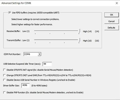
Einstellungen für COM6 UART FIFO Puffer
Advanced Settings for COM6 Use FIFO buffers (requires 16550 compatible UART) Select lower settings to correct connection problems. Select higher settings for faster performance. Receive Buffer: Low (1) High (14) (14) Transmit Buffer: Low (1) High (16) (16) COM Port Number: COM6 USB Selective
-
Thread
ATmega: Wake-Up Zeit nach Power-Down
was an sich relativ zügig geht, denn bei einem Quarz bräuchte man einige Millisekunden dafür, bei Low-Frequenz-Quarzen dauert es noch länger; und nach diesen 6 Clocks steht der Programmzähler vermutlich erstmal im Interruptvektor, wo erst der Sprungbefehl noch eingelesen und ausgeführt werden muss.
Messvorgang dann beginnt. Das Ende des Messvorgangs ist ein Portausgang, der im Pin-Change-Interrupt auf High gesetz wird – da ich im Millisekundenbereich und mit 1000 Clocks agiere, spielen ±100 Clocks bei mir keine große Rolle.
-
 Bild
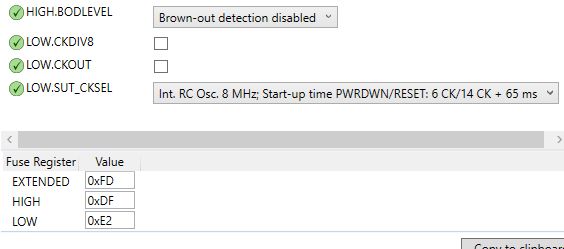
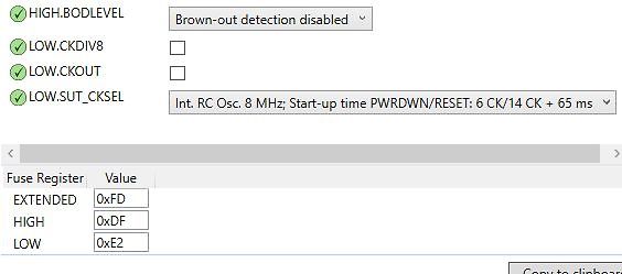
Screenshot von Mikrocontroller-Fuse-Einstellungen
HIGH.BODLEVEL Brown-out detection disabled LOW.CKDIV8 LOW.CKOUT LOW.SUT_CKSEL Int. RC Osc. 8 MHz; Start-up time PWRDWN/RESET: 6 CK/14 CK + 65 ms Fuse Register Value EXTENDED 0xFD HIGH 0xDF LOW 0xE2
-
 Bild
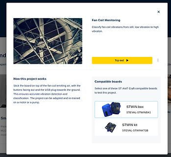
Webseite zur Fan Coil Vibration Monitoring Projektvorstellung
Fan Coil Monitoring Classify fan coil vibrations from still, low vibration to high vibration. Try out How this project works Stick the board on top of the fan coil emitting air, with the buttons facing out and the USB plug towards the ground. This ensures accurate
-
Thread
Tantalkondensatoren am Spannungsregler ersetzen
recommended that the regulator input be bypassed with capacitor ... should be selected to provide good high frequency characteristics to insure stable operation under all load conditions. A 0.33 μF or larger tantalum, mylar or other capacitor having low internal impedance at high frequencies should be chosen
-
Thread
DSO Batronix Magnova? Erfahrungen?
wiedergegeben. Die drei Farbfilter werden dann jeweils mit 60Hz Bildwechselfrequenz angesteuert. Signal low Filter durchlässig für alle Farben. Signal High Filter für die Farbe durchlässig für die das Filter gebaut ist. Es sind dadurch 6 Farben anwählbar in dem man die 3 Filter in Kombination ansteuert. (
zumindest in Betriebsarten mit nur einem Eingangssignal, z.B. UART. 3. Die Default-Schwellwerte für High und Low sollten auch bei 10:1-Tastköpfen bei 2,3 V und 1 V statt 23 V und 10 V liegen.
-
Thread
Sumd (Graupner) mit Micropython auswerten
be a kind of error indicator (1 normally.. o byte 2 = count of following channels o byte 3 = high byte of Servo 0 o byte 4 = low byte of Servo 0; raw min is 8000 max is 16000 o ... repeats over the channel count o byte n-1 = High byte of CRC o byte n = Low byte of CRC16, which is CRC-CCITT
# bs = uart1.read(2) # val = bs[0]<<8 | bs[1] # dasselbe etwas pythonischer: # high, low = uart1.read(2) # val = high<<8 | low print(f'Servo {i+1}: {val}') [/code] Hinzu kommt natürlich noch die Auswertung der ersten beiden Bytes und der CRC.
-
 Bild
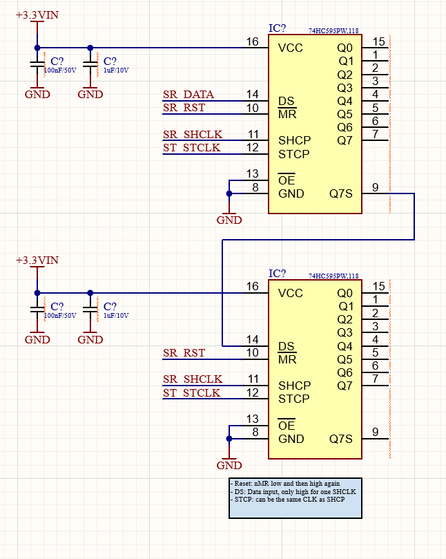
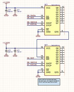
Schaltplan mit zwei 74HC595 Schieberegistern
10 DS 4 MR 5 Q4 11 SHCP 6 Q5 12 STCLK 7 Q6 13 OE 8 GND 9 Q7S SR RST SR SHCLK STCLK GND - Reset: nMR low and then high again - DS: Data input, only high for one SHCLK - STCP: can be the same CLK as SHCP
-
Thread
32-bit Shift-Counter
www.nexperia.com/product/74HC595PW Im Prinzip will ich zu Beginn eines Zyklus alle Ausgänge auf LOW haben, dann mit der CLK einfach ein HIGH über die 32 Ausgänge schieben (führt zu verschiedenen LEDs) und danach wieder alles auf LOW bis zum nächsten Zyklus.
Bert S. schrieb im Beitrag #7770491: > Im Prinzip will ich zu Beginn eines Zyklus alle Ausgänge auf LOW haben, > dann mit der CLK einfach ein HIGH über die 32 Ausgänge schieben (führt > zu verschiedenen LEDs) und danach wieder alles auf LOW bis zum nächsten > Zyklus. Counter 74HC4060, davon die
-
Thread
Code Solartracker
7, OUTPUT); pinMode (6, OUTPUT); [/pre] und auch [pre] void paso_XXX() { digitalWrite(5, LOW); digitalWrite(4, LOW); digitalWrite(3, HIGH); digitalWrite(2, HIGH); delay(retardo); digitalWrite(5, LOW); digitalWrite(4, HIGH); digitalWrite(3, HIGH); digitalWrite(2, LOW); delay(retardo); digitalWrite(5, HIGH); digitalWrite(4, HIGH); digitalWrite(3, LOW); digitalWrite(2, LOW); delay(retardo); digitalWrite(5, HIGH); digitalWrite(4, LOW); digitalWrite(3, LOW); digitalWrite(2, HIGH);
-
Thread
Raspberry Pi-Touchscreen, Arduino-Zertifikation und neuer Cortex M85-Mikrocontroller
- Mikrocontroller mit Cortex M85-Kern zum geringen Preis. ARM Cortex-M85 war bisher vor allem in High End-Mikrocontrollern vertreten - diese boten zwar sehr viel Rechenleistung, waren aber alles andere als preiswert. Mit RA8E1 und RA8E2 möchte Renesas nun - wie im Familiendiagramm gezeigt - eine Erweiterung
/attachment/651022/3.jpg) Bildquelle: https://www.renesas.com/en/about/newsroom/renesas-brings-high-performance-arm-cortex-m85-processor-cost-sensitive-applications-new-ra8-entry Weg zum Erreichen dieses Ziels ist dabei eine „Reduktion“ des Funktions-Umfangs bzw. der in den Mikrocontroller verbauten
-
Thread
Kondensatorladung über MOSFET gezielt freigeben
in den Autos (15V kommen vom Bus). Der Pegel an BAHN ist immer gleich zu TXD. Spricht bei TXD = LOW ist auch BAHN LOW, weil Q1 gesperrt ist. Bei TXD = HIGH ist Q1 durchgeschaltet und BAHN wird auf +15V gezogen. C1 kann über die Bodydiode von Q1 aufgeladen werden, wenn die Schaltung in einem Auto verbaut
-
Thread
ATmega Power-Down und Wakeup mit INT0
Schaltung kommt ein Sensor zum Einsatz. Dieser Sensor hat normalerweise ein Ausgangssignal von High. Wenn er dann das entspr. Ereignis bemerkt, wechselt er das Ausgangssignal auf Low. Wie lange das dann auf Low ist, kommt auf das Ereignis an. Dafür ist ein Flanken-Interrupt einfacher, finde ich
Abarbeitung des Interrupt-Codes der Controller schon wieder schlafen, während der Sensor noch ein Low-Signal ausgibt.
-
Thread
Attiny26-16PU startet Programm nicht
Absurdum führt) [code] void setup(){ pinMode(pin, OUTPUT); while(1){ digitalWrite(pin, HIGH); delay(500); digitalWrite(pin, LOW); delay(500); } } void loop(){ //wird nie aufgerufen } [/code]
// the loop function runs over and over again forever void loop() { digitalWrite(LED_BUILTIN, HIGH); // turn the LED on (HIGH is the voltage level) delay(1000); // wait for a second digitalWrite(LED_BUILTIN, LOW); // turn the LED off by making the voltage LOW delay
-
 Bild
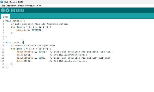
Arduino Programmcode für Blink-Funktion
} } void loop() { // Durchlaufe alle analogen Pins for (int i = 0; i < 6; i++) { digitalWrite(i, HIGH); // Setze den aktuellen Pin auf HIGH (LED ein) delay(500); // 500 Millisekunden warten digitalWrite(i, LOW); // Setze den aktuellen Pin auf LOW (LED aus) delay(500); // 500 Millisekunden warten }
-
 Bild
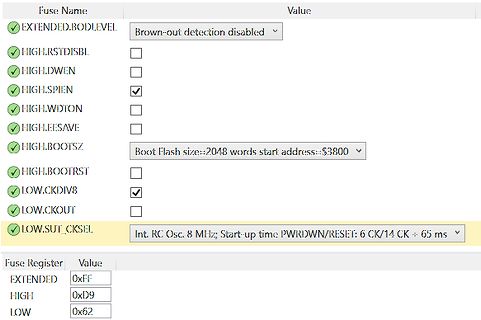
Software-Screenshot von Mikrocontroller-Fuse-Einstellungen
HIGHLEAVE HIGHBOOTSZ Boot Flash size: 2048 words start address: $3800 HIGHBOOTRST HIGHCKDIV8 HIGHCKOUT HIGH.SUT_CKSEL Int. RC Osc. 8 MHz Start up time PWRDOWN/RESET: 6 CK/14 CK = 65 ms Fuse Register Value EXTENDED 0xFF HIGH 0xD9 LOW 0x62
-
Thread
ATmega: unerwatetes Reset
Code auf dem Controller ist wie folgt: Alle Pins als Inputs mit Pullup Ein Pin (PB1) als Ausgang high while(1) Die Fuses sind so programmiert: Der Controller läuft mit dem internen RC-Oszillator und CLDIV8, also mit 1MHz. Brown-Out Dectetion und Watchdog sind abgeschaltet, ein Bootloader wird nicht
spezifiziert. Nein, tut es nicht. Nicht bei diesen alten Kamellen. Damal nutzte Atmel das V für "Low-Voltage" und das A für "Verbessert", was "Low Voltage" meist mit einbezog.
-
Thread
Owon XDM1041 - Billigheimer oder günstige Alternative
119€ aufgerufen werden: https://de.banggood.com/Owon-XDM1041-USB-Digital-Multimeter-55000-Counts-High-Accuracy-Universal-Desktop-Multimeters-Meter-with-3_5-inch-TFT-LCD-Screen-p-1847470.html?akmClientCountry=DE&cur_warehouse=CZ
Nachdem ich etwas genervt war, dass mein XDM1041 im Low-Sampling-Modus startet, habe ich per ESP32 automatisch den Sampling-Modus nach jedem Start per SCPI auf High setzen lassen. Während der Entwicklung kam mir die Idee, das Multimeter über WLAN/MQTT in
-
 Bild
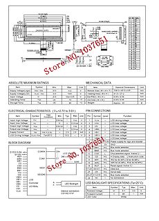
Datenblatt eines LCD-Moduls mit technischen Spezifikationen
Supply Voltage (Logic) Vcc - Vss -0.3 4.0 V Operating Temp. -20 70 °C Storage Temp. -30 80 °C Input High Voltage VIH 0.8Vcc V 1 Input Low Voltage VL 0.2Vcc V 2 Output High Voltage VOH 0.8Vcc V 3 Output Low Voltage VOL 0.2Vcc V 4 Supply Current Vcc - Vss mA 5 LCD Driving Voltage Vcc-Vss V 7 BLOCK DIAGRAM
-
Thread
Mini-Led-Treiber
Technische Daten des CN5711 und zum LDO6aJSA-Board) https://elektro.turanis.de/html/prj464/index.html Für Low-Pegel muss die Spannung unter 0.6V liegen, für High-Pegel über 2.3V
Datenblatt und liest: VDIM Internal supply voltage DIM floating 5 V VDIM_H DIM input voltage High 2.5 V VDIM_L DIM input voltage Low 0.3 V VDIM_DC DC brightness control 0.5 2.5 V fDIM Max. DIM Frequency fOSC=500kHz 50 kHz Duty cycle range of low frequency dimming fDIM =100Hz 0.02% 1
-
Thread
Neue Bauteile: STM-Drohnenkit, intelligente Steckverbinder, Stromsensoren und mehr
Datenblatt wird sie von Mirochip folgendermaßen beschrieben: [c] Computation Features: – Averaging and low-pass filter functions – Reference comparison – 2-level threshold comparison – Selectable interrupts [/c] Zum Zeitpunkt der Drucklegung gibt es rund ein Dutzend SKUs, die bis zur 28 kB Flash und
30ppb over an extended operating temperature range of -40°C to +95°C is achieved using an SC-Cut, High “Q” resonator-based design. [/c] In Hunderterstückzahlen kosten die Produkte dabei übrigens rund € 40. ### Amphenol AABP – kompakter Drucksensor Amphenol bietet mit der AABP-Serie Drucksensoren
-
 Bild
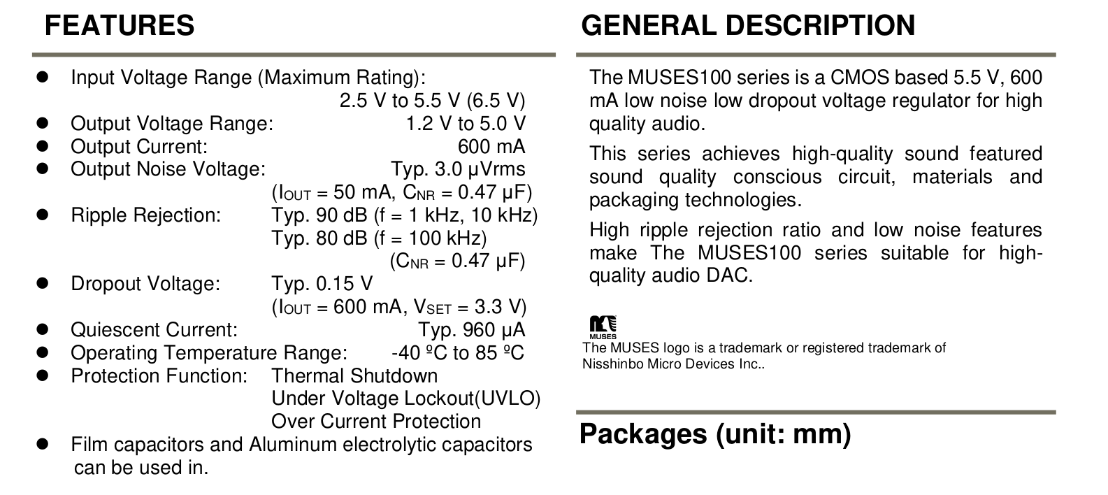
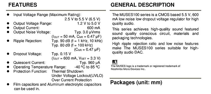
Technische Daten des MUSES100 Spannungsreglers
capacitors can be used in. GENERAL DESCRIPTION The MUSES100 series is a CMOS based 5.5 V, 600 mA low noise low dropout voltage regulator for high quality audio. This series achieves high-quality sound featured sound quality conscious circuit, materials and packaging technologies. High ripple rejection ratio and low noise features make The MUSES100 series suitable for high-quality audio DAC. Packages (unit: mm)
-
Thread
LCD Touchdisplay Fehlersuche Hintergrundbeleuchtung
kannst du das bestätigen. Wenn ja, dann ist bekannt, wo die Betriebsspannung sein muss. Ob das ein High- oder Low-Enable wäre, weiß ich nicht. > - kann ich am Inverterboard am Ausgang zu den Röhren die Spannung messen > (2xrosa und 1xweißes Kabel) mit einem Standard Multimeter? Eher nicht, jedenfalls
-
Thread
Hilfe bei DMX ArtNet-Node-Schaltplan mit Teensy 4.1
CMOS-Eingänge NIE offen lassen! OK, kleiner Fehler von mir. Pins 7 an den Optokopplern muss auf HIGH!
klar, danke für den Hinweis. > OK, kleiner Fehler von mir. Pins 7 an den Optokopplern muss auf HIGH! Laut dem Datenblatt macht es doch aber keinen Unterschied ob ich Pin 7 HIGH oder NC lasse. Ist da HIGH die bessere Lösung von beiden?