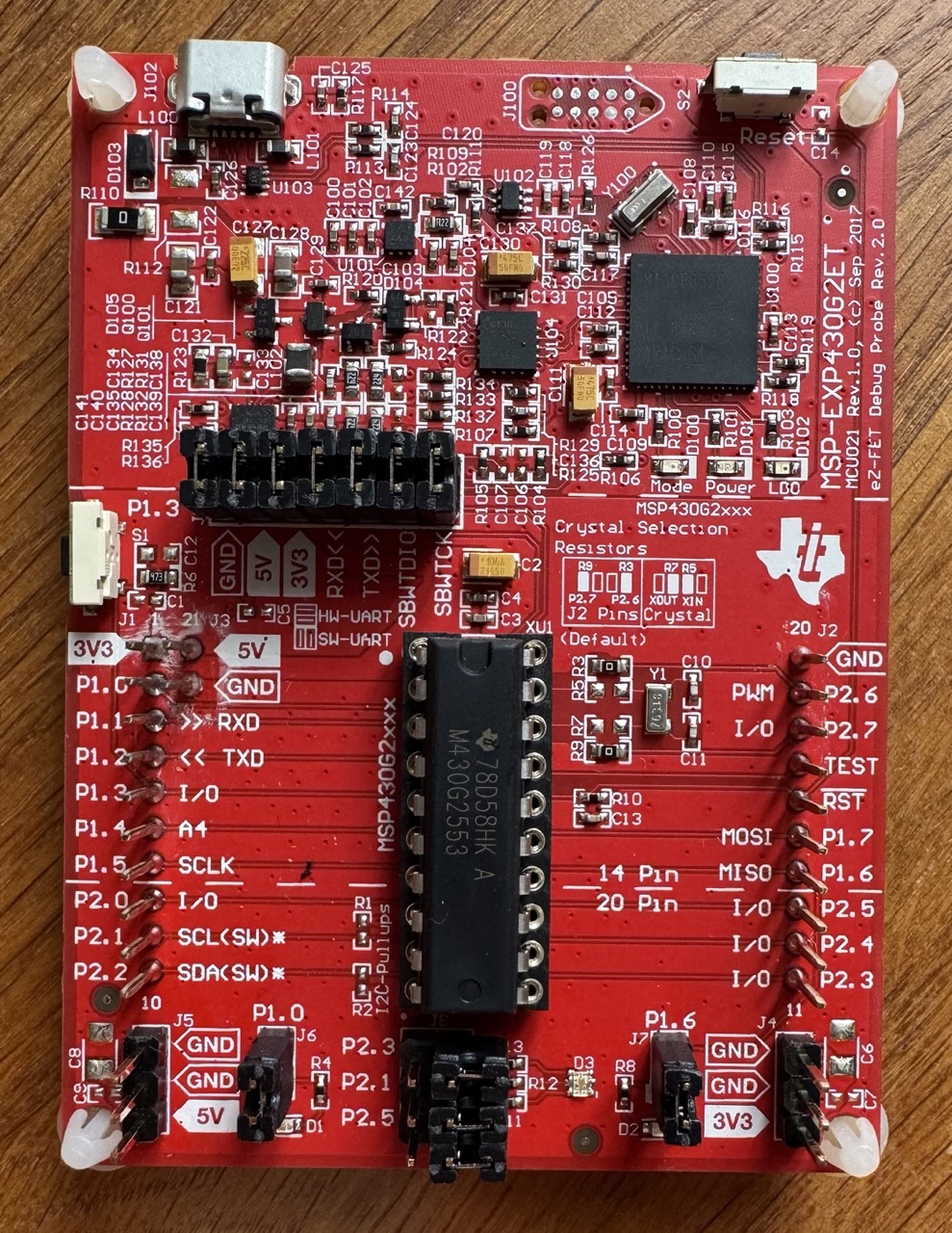
-
Datei
msp430xG46x_tb_TBIV.c
//****************************************************************************** // MSP430xG46x Demo - Timer_B, Toggle P5.1, TBCCR0 Cont. Mode ISR, DCO SMCLK // // Description: Toggle P5.1 using software and TB_0 ISR. Toggles every // 50000 SMCLK cycles. SMCLK provides clock source for TACLK
in „MSP430xG46x TimerB Capture Compare Register Funktion“ · Mikrocontroller und Digitale Elektronik ·
-
Datei
msp430xG46x_tb_TBIV_funzt.c
//****************************************************************************** // MSP430xG46x Demo - Timer_B, Toggle P5.1, TBCCR0 Cont. Mode ISR, DCO SMCLK // // Description: Toggle P5.1 using software and TB_0 ISR. Toggles every // 50000 SMCLK cycles. SMCLK provides clock source for TACLK
in „MSP430xG46x TimerB Capture Compare Register Funktion“ · Mikrocontroller und Digitale Elektronik ·
-
Datei
msp430xG46x_uscia_uart_9600.c
//****************************************************************************** // MSP430xG46x Demo - USCI_A0, Ultra-Low Pwr UART 9600 Echo ISR, 32kHz ACLK // // //****************************************************************************** #include <msp430xG46x.h> void Welcome_Note(void
in „msp430xG46x_usart1_19200.c "tested"?“ · Mikrocontroller und Digitale Elektronik ·
-
Datei
msp430xG46x_uscia0_uart_115k_lpm.c
//****************************************************************************** // MSP430xG46x Demo - USCI_A0, 115200 UART Echo ISR, DCO SMCLK, LPM3 // // Description: Echo a received character, RX ISR used. Normal mode is LPM3. // Automatic clock activation for SMCLK through the USCI is
in „EXP430FG4618 Kommunikation via RS232“ · Mikrocontroller und Digitale Elektronik ·
-
Datei
main.c
//#include "io430.h" //#include <msp430g2231.h> //#include <stdint.h> //#include "msp430x26x.h" #include <msp430g2553.h> #include "TI_USCI_I2C_master.h" // Autor: Andreas V. (Firma: anvado) (andreas_va) // EEPROM Basisadresse: 0x3333; //
in „MSP430 Aufkündigung?“ · Mikrocontroller und Digitale Elektronik ·
-
Datei
MAX5530.txt
#include "msp430x20x3.h" //Header for MSP430F2013, located at //C:\Programme\IAR Embedded Workbench\430\inc //Function prototypes void spi_init(void); //Initialization of SPI void v_out(void); //Set output voltage
in „MSP430 MSP430F2013 SPI Kommunikation mit D/A-Wandler“ · Mikrocontroller und Digitale Elektronik ·
-
Datei
msp430x46x_tb_10.c
//****************************************************************************** // MSP430xG46x Demo - Timer_B, PWM TB1-6, Up Mode, DCO SMCLK // // Description: This program generates six PWM outputs on P2/P3 using // Timer_B configured for up mode. The value in CCR0, 512-1, defines the
in „MSP430xG46x TimerB Capture Compare Register Funktion“ · Mikrocontroller und Digitale Elektronik ·
-
Datei
main.c
//****************************************************************************** // MSP430xG46x Demo - Timer_B, PWM TB1-6, Up Mode, DCO SMCLK // // Description: This program generates six PWM outputs on P2/P3 using // Timer_B configured for up mode. The value in CCR0, 512-1, defines the
in „MSP430xG46x TimerB Capture Compare Register Funktion“ · Mikrocontroller und Digitale Elektronik ·
-
Datei
msp430xG46x_tb_TBIV.c.c
//****************************************************************************** // MSP430xG46x Demo - Timer_B, Toggle P5.1, TBCCR0 Cont. Mode ISR, DCO SMCLK // // Description: Toggle P5.1 using software and TB_0 ISR. Toggles every // 50000 SMCLK cycles. SMCLK provides clock source for TACLK
in „MSP430xG46x TimerB Capture Compare Register Funktion“ · Mikrocontroller und Digitale Elektronik ·
-
Datei
LCD.c
/* Aufgabe: Initialisierung des LCD Controllers */ /* */ /* System: Controller Texas Instruments MSP430F449 */ /* Compiler CrossStudio for MSP430 Version 1.4 */ /*----------------------------------------------------------------------------*/ /* Funktionen: init_LCD */ /* clear_LCD */ /* display_LCD *
in „MSP430FG439 mit LCD“ · Mikrocontroller und Digitale Elektronik ·
-
Datei
main.c
/* * main.c */ // include the libraries // #include <msp430fr5739.h> #include <stdio.h> #include <in430.h> // define the commands // #define Start_Convert (0x51) // Initiates temperature conversions. If the part is in one-shot mode (1SHOT = 1), only one conversion
in „I2C mit MSP430FR5739 ACK wird nicht gesetzt“ · Mikrocontroller und Digitale Elektronik ·
-
Datei
msp430dayII_vr.c
autonomous speech recording // and playback. CPU runs from DCO at the default speed of 1MHz. // // MSP430FG439 // +--------------------+ // | | // | VREF+ +----/\/\/\--- // | | | // | P6.0/OA0I0|----||------+ // | | | // | | MIC // | | | // | | | // | | GND // | | // | ADC0 +-------< input from mic pre-amplifier
in „MSP 430 C-Programm verstehen“ · Mikrocontroller und Digitale Elektronik ·
-
Datei
msp430x46x_tb_10.c
//****************************************************************************** // MSP430xG46x Demo - Timer_B, PWM TB1-6, Up Mode, DCO SMCLK // // Description: This program generates six PWM outputs on P2/P3 using // Timer_B configured for up mode. The value in CCR0, 512-1, defines the
in „MSP430xG46x TimerB Capture Compare Register Funktion“ · Mikrocontroller und Digitale Elektronik ·
-
Datei
msp430x21x2_flashwrite_01.c
//****************************************************************************** // MSP430F21x2 Demo - Flash In-System Programming, Copy SegC to SegD // // Description: This program first erases flash seg C, then it increments all // values in seg C, then it erases seg D, then copies seg
in „MSP430 flash löscht sich?“ · Mikrocontroller und Digitale Elektronik ·
-
Datei
msp430xG46x_usart1_uart_2400.c
//****************************************************************************** // MSP430xG46x Demo - USART1, Ultra-Low Pwr UART 2400 Echo ISR, 32kHz ACLK // // Description: Echo a received character, RX ISR used. In the Mainloop USART1 // is made ready to receive one character with interrupt
in „msp430xG46x_usart1_19200.c "tested"?“ · Mikrocontroller und Digitale Elektronik ·
-
Datei
TBIV_switch_main.c
//****************************************************************************** // MSP430xG46x Demo - Timer_B, Toggle P5.1, TBCCR0 Cont. Mode ISR, DCO SMCLK // // Description: Toggle P5.1 using software and TB_0 ISR. Toggles every // 50000 SMCLK cycles. SMCLK provides clock source for TACLK
in „MSP430xG46x TimerB Capture Compare Register Funktion“ · Mikrocontroller und Digitale Elektronik ·
-
Datei
TS_iP152_C0802testen-a.c
// MSP430F1611 // ----------------- // | XIN|- 32,768kHz // | | // Taster rot--|RST (58) XOUT|- 32,768kHz // 8 Mhz X2IN- | // | // 8 MHz X2OUT- | P1.0..P1.7|Daten FKA usw. // | | // | P3.0| CS1 SPI frei (28)
in „LCD im 4-Bit Modus an nur einem Port betreiben“ · Mikrocontroller und Digitale Elektronik ·
-
Datei
TS_iP158_C0802testen_P1-2-1.c
// MSP430F1611 // ----------------- // | XIN|- 32,768kHz // | | // Taster rot--|RST (58) XOUT|- 32,768kHz // 8 Mhz X2IN- | // | // 8 MHz X2OUT- | P1.0..P1.7|Daten FKA usw. // | | // | P3.0| CS1 SPI frei (28)
in „LCD im 4-Bit Modus an nur einem Port betreiben“ · Mikrocontroller und Digitale Elektronik ·
-
Datei
example.c
// MSP430F169 // ----------------- // /|\| XIN|- 32,768kHz // | | | // Taster blau-|RST (58) XOUT|- 32,768kHz // | P1.7|LED Grün // 6 Mhz X2IN- | P1.6|Taster für Entladung wiederholen rechts // | P1.5|Taster
in „MSP430 über UART Daten senden“ · Mikrocontroller und Digitale Elektronik ·
-
PDF
Ultraschall.pdf
an die Leistungsstufe des Senders ¨bergibt. Als ein solcher Microcontrol¨er kame zu Beispiel der MSP430 von Texas Instruments in Frage, da dieser durch seinen niedrigen Energiever- brauch, grossen RAM und die vorhandenen Schnittstellen die Anforderungen zur Verwendung in einer Bake er¨ullen kann [6],
in „schnelle Entfernungsmessung“ · Mikrocontroller und Digitale Elektronik ·
-
PDF
slaa323a.pdf
analog-to-digital converter (ADC). An example is shown that uses this technique for the ADC12 module of an MSP430™ microcontroller (MCU) to obtain greater than 12 bits of resolution. The example code and the Gerber files for the PCB can be downloaded from www.ti.com/lit/zip/slaa323. Contents 1 Introduction....
-
Datei
DUCSPI.c
* * * *******************************************************************************/ #include <msp430x20x3.h> // Header for MSP430F2013, located at C:\Programme\IAR Embedded Workbench\430\inc //Function prototypes void spi_init(void); // Initialization of SPI for converters void v_out(char,char); /
in „MSP430 MSP430F2013 SPI Kommunikation mit D/A-Wandler“ · Mikrocontroller und Digitale Elektronik ·
-
Datei
DUCSPI.c
* * * *******************************************************************************/ #include <msp430x20x3.h> // Header for MSP430F2013, located at C:\Programme\IAR Embedded Workbench\430\inc //Function prototypes void spi_init(void); // Initialization of SPI for converters void v_out(char,char); /
in „Mit MSP430F2013 Daten senden“ · Mikrocontroller und Digitale Elektronik ·
-
Datei
msp430xG46x_usart1_19200.c
//***************************************************************************** // MSP430xG46x Demo - USART1, Ultra-Low Pwr UART 19200 Echo ISR, 32kHz ACLK // // Description: Echo a received character, USART1 RX ISR at high-speed used // with ultra-low power techniques. Normal operation
in „msp430xG46x_usart1_19200.c "tested"?“ · Mikrocontroller und Digitale Elektronik ·
-
Datei
msp430x20x3_ta_uart2400.c
//****************************************************************************** // MSP430F20xx Demo - Timer_A, Ultra-Low Pwr UART 2400 Echo, 32kHz ACLK // // Description: Use Timer_A CCR0 hardware output modes and SCCI data latch // to implement UART function @ 2400 baud. Software does
in „UART und SPI mit MSP430 (MSP430F2013), Pin-Konflikt“ · Mikrocontroller und Digitale Elektronik ·
-
Datei
main.c
//****************************************************************************** // MSP430F20xx Demo - Timer_A, Ultra-Low Pwr UART 2400 Echo, 32kHz ACLK // // Description: Use Timer_A CCR1 hardware output modes and SCCI data latch // to implement UART function @ 2400 baud. Software does
in „UART und SPI mit MSP430 (MSP430F2013), Pin-Konflikt“ · Mikrocontroller und Digitale Elektronik ·
-
Datei
msp430x20x3_ta_uart2400.c
//****************************************************************************** // MSP430F20xx Demo - Timer_A, Ultra-Low Pwr UART 2400 Echo, 32kHz ACLK // // Description: Use Timer_A CCR0 hardware output modes and SCCI data latch // to implement UART function @ 2400 baud. Software does
in „MSP430F20xx UART“ · Mikrocontroller und Digitale Elektronik ·
-
Datei
control1.c
#include <msp430x16x.h> #include <msp430def.h> void timera_init(); void timerb_init(); void mittel(); #pragma interrupt_handler timera_isr: TIMERA0_VECTOR timera_isr: TIMERA1_VECTOR #pragma interrupt_handler timerb_isr
in „[MSP430] Probleme mit dem Mikrocontroller“ · Mikrocontroller und Digitale Elektronik ·
-
Datei
control1.c
#include <msp430x16x.h> #include <msp430def.h> void timera_init(); void timerb_init(); void mittel(); #pragma interrupt_handler timera_isr: TIMERA0_VECTOR timera_isr: TIMERA1_VECTOR #pragma interrupt_handler timerb_isr
in „[MSP430] Probleme mit dem Mikrocontroller“ · Mikrocontroller und Digitale Elektronik ·
-
Datei
util_x.asm
#include "msp430f5529.h" // Einbinden der Definitionen PUBLIC INIT_UART1 PUBLIC INIT_UARTX PUBLIC TX_BYTE PUBLIC TX_String RSEG CODE ;+----------------------------------------------------------------------------- ;| SubRoutine: INIT_UART1 ;| ;| CPU.......: MSP430F5529 mit SMCLK = MCLK Std (1,048MHz) ;| ;| Stand.....: 28.10.2014 / TRE ;+----------------------------------------------------------------------------- INIT_UART1 BIS.B #BIT4, &P4OUT ; 1 = High = UART
in „MSP430 F5529 Wobbel-Generator“ · Mikrocontroller und Digitale Elektronik ·
-
Datei
util_x_2_.asm
#include "msp430f5529.h" // Einbinden der Definitionen PUBLIC INIT_UART1 PUBLIC INIT_UARTX PUBLIC TX_BYTE PUBLIC TX_String RSEG CODE ;+----------------------------------------------------------------------------- ;| SubRoutine: INIT_UART1 ;| ;| CPU.......: MSP430F5529 mit SMCLK = MCLK Std (1,048MHz) ;| ;| Stand.....: 28.10.2014 / TRE ;+----------------------------------------------------------------------------- INIT_UART1 BIS.B #BIT4, &P4OUT ; 1 = High = UART
in „Rote LED an Port 1.0 will nicht“ · Mikrocontroller und Digitale Elektronik ·
-
Datei
util_x_2_.asm
#include "msp430f5529.h" // Einbinden der Definitionen PUBLIC INIT_UART1 PUBLIC INIT_UARTX PUBLIC TX_BYTE PUBLIC TX_String RSEG CODE ;+----------------------------------------------------------------------------- ;| SubRoutine: INIT_UART1 ;| ;| CPU.......: MSP430F5529 mit SMCLK = MCLK Std (1,048MHz) ;| ;| Stand.....: 28.10.2014 / TRE ;+----------------------------------------------------------------------------- INIT_UART1 BIS.B #BIT4, &P4OUT ; 1 = High = UART
in „kein definiertes Verhalten in der ISR“ · Mikrocontroller und Digitale Elektronik ·
-
Datei
msp430x11x1_ta_uart19200_01.c
//****************************************************************************** // MSP430x11x1 Demo - Timer_A, UART 19200 Echo, HF XTAL ACLK // // Description: Use Timer_A CCR0 hardware output modes and SCCI data latch to // to implement UART function @ 9600 baud. Software does not directly
in „compilerfehlermeldung“ · Mikrocontroller und Digitale Elektronik ·
-
Datei
msp430x22x4_dco_flashcal.c
//****************************************************************************** // MSP430F22x4 Demo - DCO Calibration Constants Programmer // // NOTE: THIS CODE REPLACES THE TI FACTORY-PROGRAMMED DCO CALIBRATION // CONSTANTS LOCATED IN INFOA WITH NEW VALUES. USE ONLY IF THE ORIGINAL //
in „Flashspeicher Segment A bei ez430-rf2500 gelöscht wie wiederherstellen?“ · Mikrocontroller und Digitale Elektronik ·
-
PDF
Schematic_PIN_Geiger_2022-10-23.pdf
1 2 3 4 5 LED1 VBPW34FASR +3.3V 100K LED2 R2 VBPW34FASR C1 +3.3V U1MASTER 100nF MSP430FR2310IPW16 A A Sig0 1 P1.1/UCB0CLK/ACLK/C1/A1 P1.2/UCB0SIMO/UCB0SDA/TB0TRG/OA0-/A2/Veref- 16 SDA GND R4 R3 2 P1.0/UCB0STE/SMCLK/C0/A0/Veref+ P1.3/UCB0SOMI/UCB0SCL/OA0O/A3 15 SCL LED3 330▯' 47K SBWTCK
in „PIN Dioden Geiger“ · Mikrocontroller und Digitale Elektronik ·
-
PDF
Schematic_PIN_Geiger_2022-10-23.pdf
1 2 3 4 5 LED1 VBPW34FASR +3.3V 100K R2 VBPW34FASR C1 +3.3V U1MASTER 100nF MSP430FR2310IPW16 A A Sig0 1 P1.1/UCB0CLK/ACLK/C1/A1 P1.2/UCB0SIMO/UCB0SDA/TB0TRG/OA0-/A2/Veref- 16 SDA GND R4 R3 2 P1.0/UCB0STE/SMCLK/C0/A0/Veref+ P1.3/UCB0SOMI/UCB0SCL/OA0O/A3 15 SCL LED3 330▯' 47K SBWTCK
in „PIN Dioden Geiger“ · Mikrocontroller und Digitale Elektronik ·
-
Datei
Ausgabe_P4_Tasteingabe_2.c
/*;****************************************************************************** ; MSP430F133 ; Tasteneingabe steuert 2 Programmteile ; nach Ausführung zurück zum Hauptprogramm ; ; MSP430F133 ; _________________ ; /|\| XIN|- 32,768kHz ; | | | ; --|RST XOUT|- ; | | ; | P1.0 |-- LED (12)
in „msp430 Interrupt in C programieren“ · Mikrocontroller und Digitale Elektronik ·
-
Datei
TBIV_switch_main.c
//****************************************************************************** // MSP430xG46x Demo - Timer_B, Toggle P5.1, TBCCR0 Cont. Mode ISR, DCO SMCLK // // Description: Toggle P5.1 using software and TB_0 ISR. Toggles every // 50000 SMCLK cycles. SMCLK provides clock source for TACLK
in „MSP430xG46x TimerB Capture Compare Register Funktion“ · Mikrocontroller und Digitale Elektronik ·
-
PDF
snlu184.pdf
and a high speed interface slave device. Communication between the PC and the interface adapter’s MSP430F5529 MCU is accomplished with a standard USB-to-miniUSB cable. The MCU then communicates to the slave device via SMBus or SPI interface. Figure 1. DPS-DONGLE-EVM Board (Front). Figure 2. DPS-DONGLE-EVM
in „Tastatur komplett selbst erstellen“ · PC Hard- und Software ·
-
Datei
Wandler-Test.c
decimal *******************************************************************************/ #include <msp430x20x3.h> // Header for MSP430F2013, located at C:\Programme\IAR Embedded Workbench\430\inc //Function prototypes void spi_init_conv(void); // Initialization of SPI for converters void v_out(int); //
in „MSP430 MSP430F2013 SPI Kommunikation mit D/A-Wandler“ · Mikrocontroller und Digitale Elektronik ·
-
Datei
UART-IO.c
/* MSP430f2013 -------------- +3,5V --|DVCC GND|-- DVSS red LED --|P1.0 P2.6|-- TXD --|P1.1 P2.7|-- RXD --|P1.2 TEST|-- TEST/SBWTCK Switch2 --|P1.3 RESET|-- RST/NMI/SBWTDIO PWM 1 --|P1.4 P1.7|-- PWM 2 --|P1.5 P1.6|-- green LED -------------- */ #include "msp430g2211.h" #include "inttypes.h" #include "stdbool.h" // MSP430g2231 Signale / PINs #define TXD BIT1 // TXD an P1.1 #define RXD BIT2 // RXD an P1.2 // Timing for the Software UART #define BitTime 104
in „Problem mit UART und PWM auf MSP430G2211“ · Mikrocontroller und Digitale Elektronik ·
-
Datei
msp430_i2c.c
#include <msp430g2231.h> #include <stdio.h> #include <stdint.h> #define I2C_add_read 0xD0 #define I2C_add_write 0xD1 void main(void) { WDTCTL = WDTPW + WDTHOLD; //disable watchdog timer //-I2C init USICTL0 |= USIPE7
in „MSP430 I2C Kommunikation Slave ACK wird nicht gesendet“ · Mikrocontroller und Digitale Elektronik ·
-
 Bild
Bild
MSP-EXP430G2E2 Debug Probe Leiterplatte
MSP-EXP430G2E2 Debug Probe Rev.1.0, MSP430G2553, J100, J102, J103, J104, J105, J106, J107, J110, J111, J112, J113, J114, J115, J116, J117, J120, J121, J122, J123, J124, J125, J126, J127, J130, J131, J132, J133, J134, J135, J136, J137, J140,
in „[S] MSP430 Launchpad“ · Markt · · Platinenfotos
-
Datei
ADC.txt
#include <msp430x16x.h> ; Include header file ;------------------------------------------------------------------------------ ORG 0E000h ; Program start ;------------------------------------------------------------
in „MSP430 F1611 - Probleme bei AD-Wandlung“ · Mikrocontroller und Digitale Elektronik ·
-
Datei
msp430g2xx1_ta_uart9600.c
//****************************************************************************** // MSP430G2xx1 Demo - Timer_A, Ultra-Low Pwr UART 9600 Echo, 32kHz ACLK // // Description: Use Timer_A CCR0 hardware output modes and SCCI data latch // to implement UART function @ 9600 baud. Software does
in „Erfahrungen UART TI Launchpad“ · Mikrocontroller und Digitale Elektronik ·
-
Datei
main.c
****************************************************************** // Testcode Hardware PWM with MSP430F149/MSP430F1611 // //description: // no main functionality // clock is set by DCO , rd. 4MHz // timer B use the Outputs 4.1/4.2/4.3 // timerA update the compare value and look in pwmtable for the next
in „variable PWM mit MSP430“ · Mikrocontroller und Digitale Elektronik ·
-
Datei
main.c
//****************************************************************************** // MSP430G2xx1 Demo - Timer_A, Ultra-Low Pwr UART 9600 Echo, 32kHz ACLK // // Description: Use Timer_A CCR0 hardware output modes and SCCI data latch // to implement UART function @ 9600 baud. Software does
in „MSP430 - Timer Operation Wechsel?“ · Mikrocontroller und Digitale Elektronik ·
-
Datei
main.c
//****************************************************************************** // MSP430G2xx1 Demo - Timer_A, Ultra-Low Pwr UART 9600 Echo, 32kHz ACLK // // Description: Use Timer_A CCR0 hardware output modes and SCCI data latch // to implement UART function @ 9600 baud. Software does
in „MSP430 - Timer Operation Wechsel?“ · Mikrocontroller und Digitale Elektronik ·
-
PDF
untitled.sch.pdf
03.01.2008 19:17:22 C:\Programme\EAGLE-4.11\projects\msp430\msp4301\untitled.sch (Sheet: 1/2) 03.01.2008 19:17:22 C:\Programme\EAGLE-4.11\projects\msp430\msp4301\untitled.sch (Sheet: 2/2)
in „MSP430 - EZ430 Board“ · Mikrocontroller und Digitale Elektronik ·
-
Datei
code.c
#include <msp430x16x.h> #include <msp430def.h> #pragma interrupt_handler timera_isr: TIMERA0_VECTOR timera_isr: TIMERA1_VECTOR #pragma interrupt_handler timerb_isr: TIMERB0_VECTOR timerb_isr: TIMERB1_VECTOR #pragma
in „[MSP430] Variablenuebergabe an ISR“ · Mikrocontroller und Digitale Elektronik ·