-
Datei
vali_rc5.c
_COMP_vect #endif /* defined(__AVR_ATmega32__) */ /*****************************/ /**** TARGET = ATTINY2313 ****/ /*****************************/ #if defined(__AVR_ATtiny2313__) #define DISABLE_INT0() do { \ GIMSK &= ~(1<<INT0); \ } while(0) #define ENABLE_INT0() do { \ EIFR |= (1<<INTF0); \ GIMSK |=
in „Atmega 32 RC5“ · Mikrocontroller und Digitale Elektronik ·
-
Datei
sender.c
Fehlerberechnung #define BAUD_ERROR ((BAUD_REAL*1000)/BAUD) void timer1_init (void) { #if defined (__AVR_ATtiny45__) || defined (__AVR_ATtiny85__) // ATtiny45 / ATtiny85: OCR1C = (F_CPU / F_INTERRUPTS / 4) - 1; // compare value: 1/15000 of CPU frequency, presc = 4 TCCR1 = (1 << CTC1) | (1 << CS11) | (1 << CS10
in „16bit Zeichen über SPI übertragen“ · Mikrocontroller und Digitale Elektronik ·
-
Datei
Attiny.txt
Send: 0 [30] [20] avrdude: Send: 0 [30] [20] avrdude: Recv: . [14] avrdude: Recv: . [10] AVR Part : ATtiny85 Chip Erase delay : 400000 us PAGEL : P00 BS2 : P00 RESET disposition : possible i/o RETRY pulse : SCK serial program mode : yes parallel program mode : yes Timeout : 200 StabDelay : 100 CmdexeDelay
in „Projekt fertiggestellt: MP3 Player für Kinder auf ATTiny-Basis“ · Projekte & Code ·
-
Datei
12_Led_Lauflicht_fuer_Justin.bas
Portb 4 'Schaltplan im Ordner "Quwellcode,basic code,attiny 13 projekte '$regfile = "attiny13.dat" '$crystal = 1200000 '$hwstack = 16 '$swstack = 5 '$framesize = 16 $regfile = "attiny45.dat" $crystal = 1200000 $hwstack = 40 $swstack = 16 $framesize = 32 Macro
in „ATtiny 13 und 45 habens Programm vergessen“ · Mikrocontroller und Digitale Elektronik ·
-
Datei
12_Led_Lauflicht.bas
Portb 4 'Schaltplan im Ordner "Quwellcode,basic code,attiny 13 projekte '$regfile = "attiny13.dat" '$crystal = 1200000 '$hwstack = 16 '$swstack = 5 '$framesize = 16 $Regfile="attiny45.dat" $crystal = 1200000 $hwstack=40 $swstack=16 $framesize=32 Macro Leds_off
in „4-Kanal Lauflicht“ · Analoge Elektronik und Schaltungstechnik ·
-
Datei
irsndconfig.h
----------------------------------------------------------------------------------- * AVR ATMega/ATTiny section: * * Change hardware pin here: IRSND_OC2 = OC2 on ATmegas supporting OC2, e.g. ATmega8 * IRSND_OC2A = OC2A on ATmegas supporting OC2A, e.g. ATmega88 * IRSND_OC2B = OC2B on ATmegas supporting
in „Umfrage: welche IR-Protokolle nutzt ihr mit IRMP?“ · PC Hard- und Software ·
-
Datei
EmonLib_Cpp_comment.txt.ino
Library for openenergymonitor Created by Trystan Lea, April 27 2010 GNU GPL modified to use up to 12 bits ADC resolution (ex. Arduino Due) by boredman@boredomprojects.net 26.12.2013 Low Pass filter for offset removal replaces HP filter 1/1/2015 - RW */ // Proboscide99 10/08/2016 - Added ADMUX settings
in „ESP32: Konstante Abtastrate / Timing des ADC“ · Mikrocontroller und Digitale Elektronik ·
-
Datei
Funzt_nicht.txt
0x52 = (unknown) Device code: 0x53 = (unknown) Device code: 0x54 = (unknown) Device code: 0x55 = ATtiny12 Device code: 0x56 = ATtiny15 Device code: 0x57 = (unknown) Device code: 0x58 = (unknown) Device code: 0x59 = (unknown) Device code: 0x5a = (unknown) Device code: 0x5b = (unknown) Device code: 0x5c = ATtiny28 Device code: 0x5d = (unknown) Device code: 0x5e = ATtiny4313 Device code: 0x5f = (unknown) Device code: 0x60 = ATmega161 Device code: 0x61 = (unknown) Device code: 0x62 = (unknown) Device code: 0x63
in „Probleme mit AVRDUDESS 2.13“ · Mikrocontroller und Digitale Elektronik ·
-
Datei
small_printf.c
minimalistisches und sehr "abgespecktes" eigenes printf zu implementieren das auch noch auf einem ATtiny funktionieren soll 21.04.2016 --------------------------------------------------------------------- */ // 21.04.2016 erstmal ein Geruest erstellen damit die rs232 und ein // putchar funktionert und
in „#define Ich bekomme ein Makro nicht hin.“ · Mikrocontroller und Digitale Elektronik ·
-
PDF
AVR450_BattCharger.pdf
4.88mS V IV sat-V O 15V - 0.5V -1.5V This gives a duty cycle of ton = 4.88ms = 0.449 = 44.9 % T 9.96ms 12 AVR450 1659B–AVR–11/02 AVR450 ATtiny15 Measurement Circuitry Battery Voltage The charge voltage is measured directly on the positive battery pole. When a voltage higher than the reference voltage (3.67V
in „Pb-Akku Ladegerät mit µP Selbstgemacht“ · Mikrocontroller und Digitale Elektronik ·
-
PDF
MiniFox_1_.pdf
gemacht. Der AVR Erste Versionen des Senders arbeiteten bei mir mit den AVR-Typen AT90S2343 und ATtiny12. Diese AVR-Mikrocontroller sind inzwischen veraltet und sollten nicht mehr verwendet werden - selbst dann nicht, wenn man sie gerade herumzuliegen hat. Der jetzt von mir verwendete ATtiny45 (alle
in „Was kontrollieren, wenn man nicht "rein" kommt?“ · Mikrocontroller und Digitale Elektronik ·
-
Datei
irsndconfig.h
----------------------------------------------------------------------------------- * AVR ATMega/ATTiny section: * * Change hardware pin here: IRSND_OC2 = OC2 on ATmegas supporting OC2, e.g. ATmega8 * IRSND_OC2A = OC2A on ATmegas supporting OC2A, e.g. ATmega88 * IRSND_OC2B = OC2B on ATmegas supporting
in „IRSND Daten für Roomba“ · Mikrocontroller und Digitale Elektronik ·
-
Datei
irsndconfig.h
----------------------------------------------------------------------------------- * AVR ATMega/ATTiny section: * * Change hardware pin here: IRSND_OC2 = OC2 on ATmegas supporting OC2, e.g. ATmega8 * IRSND_OC2A = OC2A on ATmegas supporting OC2A, e.g. ATmega88 * IRSND_OC2B = OC2B on ATmegas supporting
in „IR Fernbedienung mit IRSND“ · Mikrocontroller und Digitale Elektronik ·
-
Datei
Defektfused.txt
Arduino: 1.8.13 (Windows 10), Board: "ATtiny25/45/85, ATtiny85, Internal 8 MHz" C:\Program Files (x86)\Arduino\hardware\tools\avr/bin/avrdude -CC:\Program Files (x86)\Arduino\hardware\tools\avr/etc/avrdude.conf -v -v -v -v -pattiny85 -cstk500v1
in „Projekt fertiggestellt: MP3 Player für Kinder auf ATTiny-Basis“ · Projekte & Code ·
-
Datei
main.c
irsnd.h" #ifndef F_CPU # error F_CPU unknown #endif void timer1_init (void) { #if defined (__AVR_ATtiny45__) || defined (__AVR_ATtiny85__) // ATtiny45 / ATtiny85: OCR1C = (F_CPU / F_INTERRUPTS / 4) - 1; // compare value: 1/15000 of CPU frequency, presc = 4 TCCR1 = (1 << CTC1) | (1 << CS11) | (1 << CS10
in „IRSND Daten für Roomba“ · Mikrocontroller und Digitale Elektronik ·
-
PDF
freq_zaehler_attiny.pdf
2-2 for an example. A non-inclusive list of Atmel AVR devices with this feature includes: Atmel ATtiny10, ATtiny13, ATtiny20, ATtiny26, ATtiny28, ATtiny2313, ATmega48/88/168, ATmega8, ATmega16, ATmega32, ATmega8515/8535, ATmega162, ATmega164/324/644/ 1284, and ATmega165/325/3250/645/6450. 2 AVR205 8365A-AVR-01/11 AVR205 Figure 2-2. Atmel ATtiny13A pinout. 3 Measurement principle In this application note, the “gate-open” interval was chosen to be 0.1s, or 100ms, and so the signal to be measured will clock a counter for this time interval,
in „Frequenzzähler mit ATMega32“ · Mikrocontroller und Digitale Elektronik ·
-
Datei
Netzmessung_TWI.cpp
; i2cdata[9] = stat_cosp2; i2cdata[10] = stat_cosp3; i2cdata[11] = (stat_volt1>>8) & 0xff; i2cdata[12] = (stat_volt1) & 0xff; /*TEST i2cdata[0] = 12; i2cdata[1] = 11; i2cdata[2] = 10; i2cdata[3] = 9; i2cdata[4] = 8; i2cdata[5] = 7; i2cdata[6] = 6; i2cdata[7] = 5; i2cdata[8] = 4; i2cdata[9] = 3; i2cdata
in „AVR Frequenzmessung, DS18S20“ · Mikrocontroller und Digitale Elektronik ·
-
Datei
irsndconfig.h
----------------------------------------------------------------------------------- * AVR ATMega/ATTiny section: * * Change hardware pin here: IRSND_OC2 = OC2 on ATmegas supporting OC2, e.g. ATmega8 * IRSND_OC2A = OC2A on ATmegas supporting OC2A, e.g. ATmega88 * IRSND_OC2B = OC2B on ATmegas supporting
in „IRMP - Infrared Multi Protocol Decoder“ · Projekte & Code ·
-
Datei
SPIsourceATmega.txt
-------------------------------------------------------------- fertigL: in r16,PINC ; Antwort v. ATTiny durch low-Signal auf PIN C3 sbrc r16,3 ; ATTiny fertig? rjmp fertigL ; nein clr R0 ret ;------------------------------------------------------------------------ fertigH: in r16,PINC ; Antwort v. ATTiny durch high-Signal auf PIN C3 sbrs r16,3 ; ATTiny fertig? rjmp fertigH ; nein inc R0 ret ;------------------------------------------------------------------------ ;beide Slaves stoppen SlaveStop: sbi PORTC,1 sbi PORTC,2 ret ;----------------------
in „SPI Kopplung von ATmega8 und ATtiny 2313“ · Projekte & Code ·
-
Datei
Node2_2017-11-02.ino
#define RF69_COMPAT 1 // JeeLib: RFM69 Funkmodul #define TINY 1 // JeeLib: ATtiny84 Mikrokontroller #include <JeeLib.h> int LED = 8; // LED PIN 8 bzw. Nummerierung 11 bzw. PA2, am ATtiny84 int LDRout = 1; // Digital-PIN für Fotowiderstand (Strom) int LDRin = 3; // Analog-PIN für
in „Kombination von ATtiny84A, RFM69CW, BME280 - möglich?“ · Mikrocontroller und Digitale Elektronik ·
-
PDF
ICprog-AVR.pdf
Stiftleiste J2. mega102, ATmega128, ATmega161, ATmega162, ATmega163, ATmega169, ATmega8515, ATme- ga8535 ATtiny: ATtiny10, ATtiny12, ATtiny15, ATtiny26, ATti- ny2313 AT90S: AT90S1200, AT90S2313, AT90S2323, AT90S2333, AT90S2343, AT90S4414, AT90S4433, AT90S4434, AT90S8515, AT90S8534, AT90S8535, AT90S8544 Abbildung
in „USB Programmer ICprog-AVR“ · Mikrocontroller und Digitale Elektronik ·
-
Datei
small_printf.c
minimalistischen (und im Funktionsumfang eingeschraenkten) Version von printf zur urspruenglichen Verwendung im ATtiny23 (sollte allerdings auch mit allen anderen AVR- Controllern funktionieren) 22.04.2016 R. Seelig Danke an www.mikrocontroller.net (Dr.Sommer, beric) Platzhalterfunktionen von tiny_printf ----------
in „#define Ich bekomme ein Makro nicht hin.“ · Mikrocontroller und Digitale Elektronik ·
-
Datei
AVR910JS_2313_v3_3_STK500.asm
AT90S2343 ; .db 0x4C,0 ;From 0x4d-0x4f unused yet ; ;0x50,0x51 used. From 0x52-0x54 unused yet ; ; ; ;ATtiny12 ; .db 0x55,0 ; ;ATtiny15 ; .db 0x56,0 ;0x57 unused yet ; ;ATtiny19 ; .db 0x58,0 ;From 0x59-0x5b unused yet ; ;ATtiny28 ; .db 0x5C,0 ;0x5d unused yet ; ;ATtiny26 ; .db 0x5E,'P' ;0x5f unused yet ;
in „STK500 spinnt“ · Mikrocontroller und Digitale Elektronik ·
-
Datei
tm16xx.h
Anode und zusaetzlichem Tasteninterface. Geeignet fuer: TM1651, TM1637 MCU : alle AVR ( getestet ATtiny85, ATtiny2313, ATtiny44, ATmega8, ATmega328p ) F_CPU : 8 MHz intern Pinbelegung Controller TM16xx --------------------------- PB1 CLK PB0 DIO CLK und DIO sind mit jeweils 2,2 kOhm Pop-Up Wider- staenden
in „Siebensegment und Tasten ansteuern mit TM1651 \ TM1637“ · Projekte & Code ·
-
Datei
AVR910JS_2313_v3_3.asm
yet ;AT90S2343 .db 0x4C,0 ;From 0x4d-0x4f unused yet ;0x50,0x51 used. From 0x52-0x54 unused yet ; ;ATtiny12 .db 0x55,0 ;ATtiny15 .db 0x56,0 ;0x57 unused yet ;ATtiny19 .db 0x58,0 ;From 0x59-0x5b unused yet ;ATtiny28 .db 0x5C,0 ;0x5d unused yet ;ATtiny26 .db 0x5E,'P' ;0x5f unused yet ; ;ATmega161 .db 0x60
in „AVR - suche Datei avr910.asm von Atmel“ · Mikrocontroller und Digitale Elektronik ·
-
PDF
readme_151223.pdf
integrierter DALI-Schnittstelle. Damit habe ich gearbeitet. Das Projekt besteht aus 2 Teilen: Der Hardware (ATTiny2313), programmiert in C und einem User-Interface, realisiert mit Python / TKinter. 1.) Hardware + C-Programm EinATTiny2313 fungiert als Gateway zwischen serieller Schnittstelle und dem DALI-Bus. Der
in „RS232-DALI-Gateway für ATtiny2313 / Python-GUI“ · Projekte & Code ·
-
Datei
irsnd-main-avr.c
} // end gigaset specific code // IRSND starts here void timer1_init (void) { #if defined (__AVR_ATtiny45__) || defined (__AVR_ATtiny85__) // ATtiny45 / ATtiny85: OCR1C = (F_CPU / F_INTERRUPTS / 4) - 1; // compare value: 1/15000 of CPU frequency, presc = 4 TCCR1 = (1 << CTC1) | (1 << CS11) | (1 << CS10
in „Konzeption einer IR Fernbedienung“ · Mikrocontroller und Digitale Elektronik ·
-
Datei
Fernbedienung_mit_IRSND_mega8.c
Andreas */ #define F_CPU 8000000L #include "irsnd.h" void timer1_init (void) { #if defined (__AVR_ATtiny45__) || defined (__AVR_ATtiny85__) // ATtiny45 / ATtiny85: OCR1C = (F_CPU / F_INTERRUPTS / 4) - 1; // compare value: 1/15000 of CPU frequency, presc = 4 TCCR1 = (1 << CTC1) | (1 << CS11) | (1 << CS10
in „IR Fernbedienung mit IRSND“ · Mikrocontroller und Digitale Elektronik ·
-
Datei
Fernbedienung_mit_IRSND_mega8.c
Andreas */ #define F_CPU 8000000L #include "irsnd.h" void timer1_init (void) { #if defined (__AVR_ATtiny45__) || defined (__AVR_ATtiny85__) // ATtiny45 / ATtiny85: OCR1C = (F_CPU / F_INTERRUPTS / 4) - 1; // compare value: 1/15000 of CPU frequency, presc = 4 TCCR1 = (1 << CTC1) | (1 << CS11) | (1 << CS10
in „IR Fernbedienung mit IRSND“ · Mikrocontroller und Digitale Elektronik ·
-
Datei
felermeldung.txt
Uefuse:w:0xff:m -Uhfuse:w:0xdf:m -Ulfuse:w:0x62:m avrdude: Version 6.3, compiled on Jan 17 2017 at 12:00:53 Copyright (c) 2000-2005 Brian Dean, http://www.bdmicro.com/ Copyright (c) 2007-2014 Joerg Wunsch System wide configuration file is "C:\Program Files (x86)\Arduino\hardware\tools\avr/etc/avrdude.conf
in „Fehler beim Flashen des ATtiny85 mit dem Arduino uno“ · Mikrocontroller und Digitale Elektronik ·
-
Datei
servo12.asm
; Einfachste Servoansteuerung mit einfacher Timer0 Interruptroutine ; Da ATtiny12 kein SRAM hat, nur in Assembler möglich ; Steuerung über drei Taster an PB0, PB1 und PB2, die parallel auch ; zum Programmieren benutzt werden können. ; Servopuls Out an PB4, ein zweiter Servo oder
in „einfachste Servoansteurung mit alten ATTiny12“ · Projekte & Code ·
-
Datei
intTest.lst
4.1 (C)2018 by DG4FAC ---------------------------------------------------------- Quelldatei: C:\ATtiny85 Lernpaket\Assembler-Files\intTest\intTest.asm Hexdatei: C:\ATtiny85 Lernpaket\Assembler-Files\intTest\intTest.hex Eepromdatei: C:\ATtiny85 Lernpaket\Assembler-Files\intTest\intTest.eep Kompiliert: 24.02.2019, 12:25:45 Durchgang: 2 1: ; 2: ; ********************************* 3: ; * * 4: ; * * 5: ; ********************************* 6: ; 7: .nolist 10: ; 11: ; ********************************** 12: ; H A R D W
in „attiny85 interrupt-behandlung“ · Mikrocontroller und Digitale Elektronik ·
-
Datei
SPIsourceATtiny.txt
Datenübertragung per SPI ; Schaltung : SPI: MOSI, MISO, SCK ATMega8 zu ATTinys lt. Datenblatt ; ATMega8 - ATTiny2313 ; C1 - B0 ; C2 - B0 ; C3 - B1 ; ATtiny2313 auf Steckboard verbunden mit ATMega8 auf MYAVR-Board ; verbunden über SPI, ATMega als Master, ATTiny als Slave ; zur Anzeige steuern die MCUs jeweils LEDs, ATmega mit Taster und LED ; ATtiny mit LED an D1 ; Verbindung Steckboard - MYAVR-Board: +,-,MOSI, MISO, SCK, Software-SS, Bereit, LED (2313 Pins 20,10,17,18,19,12,13,3) ;--------------------------------------------------------------
in „SPI Kopplung von ATmega8 und ATtiny 2313“ · Projekte & Code ·
-
PDF
TSL230_ReadMe_110717.pdf
Messung der Beleuchtungsstärke mit TSL230 und ATtiny2313 in C Messung der Beleuchtungsstärke mit Light-to-Frequency-Converter TSL230R und ATtiny2313 in C 1.) Allgemeines Der Light_To_Frequency-Converter TSL230 erzeugt an seinem Ausgangspin einen Takt
in „Messung der Beleuchtungsstärke mit TSL230R und ATtiny2313 in C“ · Projekte & Code ·
-
Datei
optiboot_atmega128.lst
external reset 1fc16: 29 f0 breq .+10 ; 0x1fc22 <try_loader> 0001fc18 <appStart>: #if (defined(__AVR_ATtiny841__) || defined(__AVR_ATtiny441__) || defined(__AVR_ATtiny1634__)) && (WATCHDOG_TIME == WATCHDOG_OFF) ldi r21, 0xD8 ; special signature to change protected I/O register AOUT CCP, r21 AOUT WDTCSR,
in „Tester für Spezialversion des AVR Bootloaders optiboot gesucht!“ · Mikrocontroller und Digitale Elektronik ·
-
Datei
irsnd-main-avr.c
} // end gigaset specific code // IRSND starts here void timer1_init (void) { #if defined (__AVR_ATtiny45__) || defined (__AVR_ATtiny85__) // ATtiny45 / ATtiny85: OCR1C = (F_CPU / F_INTERRUPTS / 4) - 1; // compare value: 1/15000 of CPU frequency, presc = 4 TCCR1 = (1 << CTC1) | (1 << CS11) | (1 << CS10
in „IR Fernbedienung mit IRSND“ · Mikrocontroller und Digitale Elektronik ·
-
PDF
Bitwackler.pdf
um mit dem Chip noch einmal kommunzizieren zu können). ACHTUNG: Die folgende Anweisung stellt den ATtiny2313 auf externen Quarz um, es muß zwinend ein Quarz wie im Schaltplan angeschlossen sein: Um die Fuses für einen Betrieb als USBtiny-Programmer (mit externem 12 MHz Quarz) zu setzen wird am „DOS-Prompt
in „Zeigt her eure "Grottenwerke"“ · Mikrocontroller und Digitale Elektronik ·
-
Datei
Original.c.c
/*************************************************************************************** Titel: ATtiny TPS Author: Christian Hottum File: ATtiny461A_TPS.c Version: 0.1 Datum: 09.01.2015 Software: AVR-GCC 4.3.3 Target: ATtiny461A DESCRIPTION Firmware für einen Tasten Programierbare Steuerung auf Basis
in „Ttiny 461a isp schaltung“ · Mikrocontroller und Digitale Elektronik ·
-
PDF
AVR051.pdf
External RC Oscillator 8-bit Features RISC • Low Power Consumption. Wide Frequency Range 100 kHz - 12 MHz Microcontroller Programmable Frequency Range to Minimize Current Consumption for a desired Frequency Applicability Application This application note applies to all AVRs with External RC Oscillator except ATtiny11, Note ATtiny12, ATtiny28, ATmega163, and ATmega323. For these devices, please refer to the device datasheets. Introduction This application note describes how to use the external RC oscillator for
in „AtMega32 mit Quarz betreiben. [siehe Bild]“ · Mikrocontroller und Digitale Elektronik ·
-
Datei
iotn5.h
iotn5.h" #else # error "Attempt to include more than one <avr/ioXXX.h> file." #endif #ifndef _AVR_ATtiny5_H_ #define _AVR_ATtiny5_H_ 1 /* Registers and associated bit numbers. */ #define PINB _SFR_IO8(0x00) #define PINB0 0 #define PINB1 1 #define PINB2 2 #define PINB3 3 #define DDRB _SFR_IO8(0x01) #define
in „direkt in ein Register des Tiny5 schreiben“ · Mikrocontroller und Digitale Elektronik ·
-
Datei
main.c
debounce.h" #ifndef F_CPU # error F_CPU unknown #endif void timer1_init (void) { #if defined (__AVR_ATtiny45__) || defined (__AVR_ATtiny85__) // ATtiny45 / ATtiny85: OCR1C = (F_CPU / F_INTERRUPTS / 4) - 1; // compare value: 1/15000 of CPU frequency, presc = 4 TCCR1 = (1 << CTC1) | (1 << CS11) | (1 << CS10
in „Konzeption einer IR Fernbedienung“ · Mikrocontroller und Digitale Elektronik ·
-
PDF
Universeller_RC5-Fernbedienungsempf__nger_.pdf
und F1 direkt aus dem Lichtnetz bezogen. Z-Diode D2 sorgt für eine erste Begrenzung der Spannung auf 12 V, der -5-V- Festspanungsregler sorgt nach der Gleichrichtung durch D1 für den Rest. Über das IR-Empfangsmodul sind nicht viele Worte zu ver- lieren, es handelt sich um einen gut erhältlichen und preis
in „Universeller RC5-Fernbedienungsempfänger“ · Mikrocontroller und Digitale Elektronik ·
-
Datei
attiny2313.bas
'------------------------------------------------------------------------------- 'Regfile für Attiny 2313 $regfile = "attiny2313.dat" '------------------------------------------------------------------------------- 'Ausgänge und Eingänge definieren und konfigurieren. 'Interrupt auf PIND.2 Config Portb
in „Attiny2313 Herz - Interrupt Problem“ · Mikrocontroller und Digitale Elektronik ·
-
PDF
ATtiny212_412-Errata-and-Clarification-DS40002114B.pdf
ATtiny212/412 ATtiny212/412 Silicon Errata and Data Sheet Clarification The ATtiny212/412 devices you have received conform functionally to the current device data sheet (DS40001911), except for the anomalies
in „Attiny412 Temperatur intern“ · Mikrocontroller und Digitale Elektronik ·
-
PDF
AVR042_Hardware_Design_Considerations_doc2521.pdf
target application board so that the ISP connectors can be accessed easily. Note: 1. Except the ATtiny10, ATtiny11 and ATtiny28. On most devices the ISP interface is located on the same pins as the SPI interface. However, there are exceptions from this rule, e.g. the ATmega103 and the ATmega128 do not
in „Atmega 8A PU“ · Mikrocontroller und Digitale Elektronik ·
-
PDF
AVR053.pdf
Grouped by oscillator version. Oscillator version Device RC oscillator frequency [MHz] CKDIV PRSCK 1.1 ATtiny12 1.2 1.2 ATtiny15 1.6 2.0 ATmega163 1.0 2.0 ATmega323 1.0 3.0 ATmega8 1.0, 2.0, 4.0, and 8.0 3.0 ATmega16 1.0, 2.0, 4.0, and 8.0 3.0 ATmega32 1.0, 2.0, 4.0, and 8.0 (1) 3.1 ATmega64 1.0, 2.0, 4.0,
in „OSCCAL für 8MHz ?!? be ATTiny26“ · Mikrocontroller und Digitale Elektronik ·
-
PDF
AVR053.PDF
Grouped by oscillator version. Oscillator version Device RC oscillator frequency [MHz] CKDIV PRSCK 1.1 ATtiny12 1.2 1.2 ATtiny15 1.6 2.0 ATmega163 1.0 2.0 ATmega323 1.0 3.0 ATmega8 1.0, 2.0, 4.0, and 8.0 3.0 ATmega16 1.0, 2.0, 4.0, and 8.0 3.0 ATmega32 1.0, 2.0, 4.0, and 8.0 (1) 3.1 ATmega64 1.0, 2.0, 4.0,
in „Osccal für EEPROM bei mega8535 mit Quarz“ · Mikrocontroller und Digitale Elektronik ·
-
Datei
usiTwiSlave.c
Activity: Date Description ------ ------------- 16 Mar 2007 Created. 27 Mar 2007 Added support for ATtiny261, 461 and 861. 26 Apr 2007 Fixed ACK of slave address on a read. 04 Jul 2007 Fixed USISIF in ATtiny45 def 12 Dev 2009 Added callback functions for data requests **********************************
in „Referenz von "usi_onReceiverPtr"“ · Mikrocontroller und Digitale Elektronik ·
-
PDF
Sheet1.pdf
PIR702PIR70P1IDPID202 IC1C VCC 1.5k 1 5 LED0 PI2C10IN OUT PIIC105 P0 P0 COD3 GND PI3C10GND 4 C1C1 12 C2C2 D3 +5V PIIC10EN NR PIIC104 P2 2 R1R P1 100nF PIR802PIR80P1IDPID302 TPS73033 2 4.7k 1.5k COC3 10 COIC GND LED0GND 41 PIC3022pFC302 IC2 C4C PIX202PIX201 GND PIIC20RST/PA2 VCC PIIC2020 42 u C5C5 PIIC20RXD
in „[V] USB-RF-Stick (eigenentwicklung) mit 8MB Flash“ · Markt ·
-
 Bild
Bild
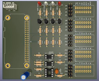
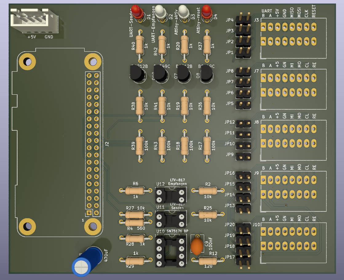
CAD-Ansicht eines Leiterplatten-Layouts
+5V GND UART-Sende D1 UART-Empfang D2 Attiny-aktiv D3 Attiny-reset D4 JP4 JP3 J3 B A +5V GND MOSI CLK RESET R40 1k R42 1k JP2 JP1 R37 1k 12B 49C 2B B 9C JP8 J7 B A +5V GND MOSI CLK RE R38 10k R41 10k R19 10k R36 10k JP5 JP12 JP11 J8 B A +5V GND MOSI CLK RE JP10 JP9 B A +5V GND MOSI CLK RE JP16 JP15 J9 R6 LTV-817 U12 Empfangen R2 10k R27 10k U11 LTV-817 Senden R25 JP14 JP13 R4 560 U10 SN75176 BP JP20 JP19 J10 B A +5V GND MOSI CLK RE R28 1k C9 100nF JP18 JP17 R29 120
in „BME280 mit Attiny85 auslesen Daten per SN75176 an Pi senden“ · Mikrocontroller und Digitale Elektronik · · Layouts