-
PDF
RL-Extender.pdf
......................................12 8 ROLLLADEN-SIMULATOR 14 9 QUELLCODE UND DESSEN COPYRIGHT 15 10 AKTUELLER STAND DER ARBEITEN 16 11 STROMLAUFPLAN 17 12 QUELLENANGABEN 18 Rollladen-Extender Beschreibung Copyright (c) BBC-Hörer 2016-2018 - 3 - 1 Prämissen und Features Erweiterung der bestehenden Steuerung zur Steuerung eines einzelnen Rollladens auf AVR-Basis mit ATtiny84 Optimiertes Design hinsichtlich Aufbautechnik und Zuverlässigkeit Programmstruktur, welche Adaptionen der Firmware rückwirkungsfrei zulässt Remanente Speicherung projektierter Daten im EEPROM
-
Datei
ATtiny804_814_824.html
<!DOCTYPE html> <html> <head> <meta charset="utf-8"> <title>ATtiny 804 - 814 - 824</title> <style type="text/css"> body {background:#f5f6f7} article {margin:10px auto 300px auto;width:1200px;font:15px arial} div {padding:5px 0} table {border-collapse:collapse;background:#fafbfc} th {font:bold 20px arial;background:#555555;color:#ffffff;padding:15px;border:2px solid #bbbbbb} td {width:33.3%;vertical-align:top;padding:10px;border:2px solid #bbbbbb} p {margin:0;font:15px arial} </style> </head> <body> <article> <table> <tr><th>ATtiny804</th><th>
in „ATtiny Typenchaos bei Microchip“ · Mikrocontroller und Digitale Elektronik ·
-
Datei
USI_TWI_Master.h
* * Supported devices : All device with USI module can be used. * The example is written for the ATtiny2313 * * AppNote : AVR310 - Using the USI module as a TWI Master * * This is modified to just do I2C communication on ATtiny2313 running at * 1MHz. Fast mode is probably possible, but would need a faster clock * and has not been tested. * * 12/15/08 Added declaration of USI_TWI_Start_Memory_Read -jkl ****************************************************************************/ //********** Defines **********// // Defines controlling timing limits
in „USI TWI ATtiny84a Master Daten aus Sensor auslesen“ · Mikrocontroller und Digitale Elektronik ·
-
PDF
SermultiChip.pdf
Display Pinbelegung A HV 4 3 2 F 1 B G E C BAT D Backplane 30 29 28 27 26 25 24 23 22 21 20 19 18 17 16 15 14 13 12 11 10 09 08 07 06 05 04 03 02 01 Pinbelegung am Chip D3 E2 F2 A2 B2 C2 D2 E1 G1 F1 A1 16 17 19 20 21 22 23 24 25 26 27 B3 15 28 B1 F3 14 29 C1 E3 13 30 D1 B/C4 12 + G4 11 Back1,2,3 G3 9 A3 8
in „Multimeter mit serieller Schnittstelle für unter 10€“ · Projekte & Code ·
-
Datei
Values.txt
SB130 19 P1-13 19 1uF 18 TPSTP10SQ 18 OR 18 LF351N 18 FT232RL 18 BC337 18 B 18 27p 18 1N4148DO35-10 18 15p 18 15k 17 BC847 17 560 17 47n 17 200k 16 SE14 16 60R 16 470pF 16 22 16 12 Ohm 16 12k 16 10-XX 16 1,0 uF 16 10 nF 16 100nf 15 HDSP-B56Z 15 74164N 15 47p 15 47K 15 470n 15 3k3 15 390 15 18p 15 100u 15
in „[KiCad] Bibliotheksaufbau - Konzeptideen gesucht“ · Platinen ·
-
PDF
readme_151223.pdf
integrierter DALI-Schnittstelle. Damit habe ich gearbeitet. Das Projekt besteht aus 2 Teilen: Der Hardware (ATTiny2313), programmiert in C und einem User-Interface, realisiert mit Python / TKinter. 1.) Hardware + C-Programm EinATTiny2313 fungiert als Gateway zwischen serieller Schnittstelle und dem DALI-Bus. Der
in „RS232-DALI-Gateway für ATtiny2313 / Python-GUI“ · Projekte & Code ·
-
Datei
Arduino.h
LSBFIRST 0 #define MSBFIRST 1 #define CHANGE 1 #define FALLING 2 #define RISING 3 #if defined(__AVR_ATtiny24__) || defined(__AVR_ATtiny44__) || defined(__AVR_ATtiny84__) #define DEFAULT 0 #define EXTERNAL 1 #define INTERNAL1V1 2 #define INTERNAL INTERNAL1V1 #elif defined(__AVR_ATtiny25__) || defined(__AVR_ATtiny45__) || defined(__AVR_ATtiny85__) #define DEFAULT 0 #define EXTERNAL 4 #define INTERNAL1V1 8 #define INTERNAL INTERNAL1V1 #define INTERNAL2V56 9 #define INTERNAL2V56_EXTCAP 13 #else #if defined(__AVR_ATmega1280__) || defined(_
in „Sekunden,Minuten zählen mit der Funktion Millis()“ · Mikrocontroller und Digitale Elektronik ·
-
Datei
14_4_T13_I2C_PCF_LCD_MC.asm
geändert für MC Forum ;* Title : 14__T13_I2C_PCF_LCD.asm==> Version: 0.0 ;* Status: now functional Mon. 15.06.2020 ;* ;* Last updated : 05-06-2020 zuhause ;* Target_IC : ATtiny13 ;* Copyright: : Josef Fenk ;* Support email: josef.fenk@t-online.de ;* ;* Beschreibung/DESCRIPTION ;* Tiny13 controls via PCF8574
in „AVR ATtiny13 I2C PCF8574 LCD Display Ansteuerung“ · Mikrocontroller und Digitale Elektronik ·
-
Datei
mega8.txt
R16 brne W_100us_2 pop R16 dec R16 brne W_100us_3 pop R16 ret ByteTransf: sbic PINC,3 ; Antwort v. ATTiny durch low-Signal auf PIN C3 rjmp ByteTransf ; ATTiny noch nicht bereit rcall SPI_senden ; Byte senden fertig: sbis PORTC,3 ; Antwort v. ATTiny durch high-Signal auf PIN C3 rjmp fertig ; ATTiny noch
in „SPI Kopplung von ATmega8 und ATtiny 2313“ · Projekte & Code ·
-
Datei
User_def_chars.asm
der Charakterpixel ; ; keine Nullterminierung ascii_0: ; Pixel des Charakters ASCII_00 .db 0x1F, 0x15, 0x15, 0x1F, 0x15, 0x15, 0x1F, 0x00 ; ascii_1: ; Pixel des Charakters ASCII_01 .db 0x00, 0x04, 0x04, 0x1F, 0x04, 0x04, 0x00, 0x00 ; ascii_2: ; Pixel des Charakters ASCII_02 .db 0x1F, 0x1B, 0x1B, 0x00
in „Lcd die 1000ste“ · Mikrocontroller und Digitale Elektronik ·
-
 Bild
Bild
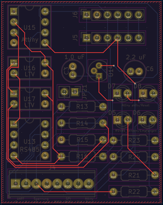
CAD-Ansicht eines Leiterplatten-Layouts
U15 Attiny, J6, 1 RISE, 2 GND, 3 CLK, 4 NO, 5 SDA, 6 SCL, J5, 1 TX, 2 GND, 3 CLK, 4 NO, 5 SDA, 6 SCL, 2,2 uF, C6, 1,0 uF, U16 LTV, U17 LTV, D7, D8, 1 RISE, 1 GND, JP21, R13, R14, D5, D6, 1 GND, 1 MISC, R15
in „BME280 mit Attiny85 auslesen Daten per SN75176 an Pi senden“ · Mikrocontroller und Digitale Elektronik · · Layouts
-
Datei
tm16xx.h
Anode und zusaetzlichem Tasteninterface. Geeignet fuer: TM1651, TM1637 MCU : alle AVR ( getestet ATtiny85, ATtiny2313, ATtiny44, ATmega8, ATmega328p ) F_CPU : 8 MHz intern Pinbelegung Controller TM16xx --------------------------- PB1 CLK PB0 DIO CLK und DIO sind mit jeweils 2,2 kOhm Pop-Up Wider- staenden
in „Siebensegment und Tasten ansteuern mit TM1651 \ TM1637“ · Projekte & Code ·
-
Datei
PWM_AD_Tiny15.bas
Potentiometer an PB5/ADC0 ' '---------------------------------------------------------- '$tiny $regfile = "Attiny15.dat" 'Attiny15-Deklarationen $crystal = 1600000 'interner Takt 1,6Mhz Ddrb.1 = 1 'OC1A ist der PWM-Ausgang Ddrb.2 = 0 'ADC 2 ist Eingang für Poti 'Pin OC1A nicht invertiert, 8-Bit- Tccr1 = &B01010010
in „Problem mit Tiny15 und PWM“ · Mikrocontroller und Digitale Elektronik ·
-
Datei
PWM_AD_Tiny15.bas
Potentiometer an PB2/ADC1 ' '---------------------------------------------------------- '$tiny $regfile = "Attiny15.dat" 'Attiny15-Deklarationen $crystal = 1600000 'interner Takt 1,6Mhz Ddrb.1 = 1 'OC1A ist der PWM-Ausgang Ddrb.2 = 0 'ADC 2 ist Eingang für Poti 'Pin OC1A nicht invertiert, 8-Bit- Tccr1 = &B11110010
in „Problem mit Tiny15 und PWM“ · Mikrocontroller und Digitale Elektronik ·
-
Datei
irsndconfig.h
* * Copyright (c) 2010-2015 Frank Meyer - frank(at)fli4l.de * * $Id: irsndconfig.h,v 1.75 2015/06/15 11:40:55 fm Exp $ * * This program is free software; you can redistribute it and/or modify * it under the terms of the GNU General Public License as published by * the Free Software Foundation; either
in „Umfrage: welche IR-Protokolle nutzt ihr mit IRMP?“ · PC Hard- und Software ·
-
Datei
main.c
(Pointer) 0xa1, 0x00, // COLLECTION (Physical) 0x09, 0x30, // USAGE (X) 0x09, 0x31, // USAGE (Y) 0x15, 0x00, // LOGICAL_MINIMUM (0) 0x26, 0xff, 0x00, // LOGICAL_MAXIMUM (255) 0x75, 0x08, // REPORT_SIZE (8bits) 0x95, 0x04, // REPORT_COUNT (2) 0x81, 0x02, // INPUT (Data,Var,Abs) 0xc0, // END_COLLECTION
in „Problem mit libUSB - wie Gerät ansprechen?“ · Softwareentwicklung ·
-
Datei
main.c
500 kHz); 4 = 010 (250 kHz); 8 = 011 (125 kHz); 16 = 100 (62,5 kHz); 32 = 101 (31,25 kHz); 64 = 110 (15,625 kHz); 128 = 111 (7,8125 kHz) ADCSRA = (1 << ADPS2) | (1 << ADPS1) | (0 << ADPS0); // Prescaler = 64 --> 15.625 kHz ADCSRA |= (1 << ADEN); // Enable ADC } void read_ADC3_Pin2_Rfoto(){ Init_ADC3_Pin2
in „Attiny85 ADC Eingangswiderstand - wie hoch“ · Mikrocontroller und Digitale Elektronik ·
-
Datei
dude5.4arduino_avr910.txt
0x52 = (unknown) Device code: 0x53 = (unknown) Device code: 0x54 = (unknown) Device code: 0x55 = ATtiny12 Device code: 0x56 = ATtiny15 Device code: 0x57 = (unknown) Device code: 0x58 = (unknown) Device code: 0x59 = (unknown) Device code: 0x5a = (unknown) Device code: 0x5b = (unknown) Device code: 0x5c = (unknown) Device code: 0x5d = (unknown) Device code: 0x5e = ATtiny2313 Device code: 0x5f = (unknown) Device code: 0x60 = ATMEGA161 Device code: 0x61 = (unknown) Device code: 0x62 = (unknown) Device code: 0x63 = ATMEGA162 Device code: 0x64 = ATMEGA163 Device code:
in „avrdude - Probleme unter Mac OS X 10.7 (Lion)“ · Mikrocontroller und Digitale Elektronik ·
-
Datei
dude54arduino.txt
0x52 = (unknown) Device code: 0x53 = (unknown) Device code: 0x54 = (unknown) Device code: 0x55 = ATtiny12 Device code: 0x56 = ATtiny15 Device code: 0x57 = (unknown) Device code: 0x58 = (unknown) Device code: 0x59 = (unknown) Device code: 0x5a = (unknown) Device code: 0x5b = (unknown) Device code: 0x5c = (unknown) Device code: 0x5d = (unknown) Device code: 0x5e = ATtiny2313 Device code: 0x5f = (unknown) Device code: 0x60 = ATMEGA161 Device code: 0x61 = (unknown) Device code: 0x62 = (unknown) Device code: 0x63 = ATMEGA162 Device code: 0x64 = ATMEGA163 Device code:
in „avrdude - Probleme unter Mac OS X 10.7 (Lion)“ · Mikrocontroller und Digitale Elektronik ·
-
 Bild
Bild
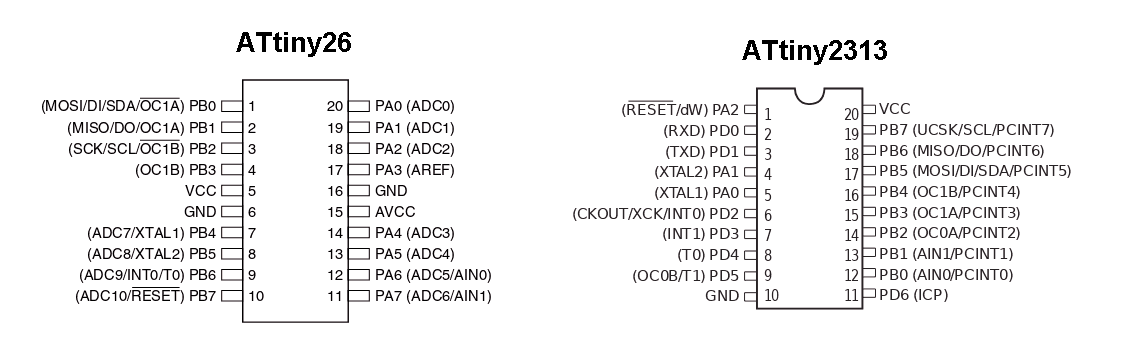
Pinbelegung ATtiny26 und ATtiny2313
ATtiny26 (MOSI/DI/SDA/OC1A) PB0 1 20 PA0 (ADC0) (MISO/DO/OC1A) PB1 2 19 PA1 (ADC1) (SCK/SCL/OC1B) PB2 3 18 PA2 (ADC2) (OC1B) PB3 4 17 PA3 (AREF) VCC 5 16 GND GND 6 15 AVCC (ADC7/XTAL1) PB4 7 14 PA4 (ADC3)
in „Suche Attiny26L-8SU (NOS)“ · Markt · · Screenshots
-
Datei
tm16xx.c
Anode und zusaetzlichem Tasteninterface. Geeignet fuer: TM1651, TM1637 MCU : alle AVR ( getestet ATtiny85, ATtiny2313, ATtiny44, ATmega8, ATmega328p ) F_CPU : 8 MHz intern Pinbelegung Controller TM16xx --------------------------- PB1 CLK PB0 DIO CLK und DIO sind mit jeweils 2,2 kOhm Pop-Up Wider- staenden
in „Siebensegment und Tasten ansteuern mit TM1651 \ TM1637“ · Projekte & Code ·
-
PDF
AVRDUDE-doc-5.5.pdf
Example Command Line Invocations ........................ 11 3 Terminal Mode Operation................. 15 3.1 Terminal Mode Commands.................................. 15 3.2 Terminal Mode Examples................................... 16 4 Configuration File ........................ 19 4.1 AVRDUDE Defaults..
in „USB-ISP PRogrammer unter Ubuntu“ · PC Hard- und Software ·
-
PDF
40001893B.pdf
8-bit AVR Microcontroller ATtiny1614 / ATtiny1616 / ATtiny1617 Introduction ® The ATtiny1614/1616/1617 is a member of the tinyAVR 1-series of microcontrollers, using the 8-bit AVR processor with hardware multiplier, running at up
in „ATtiny1614 CPU Takt Problem“ · Mikrocontroller und Digitale Elektronik ·
-
PDF
ATtiny1614_1616_1617.pdf
8-bit AVR Microcontroller ATtiny1614 / ATtiny1616 / ATtiny1617 Introduction ® The ATtiny1614/1616/1617 is a member of the tinyAVR 1-series of microcontrollers, using the 8-bit AVR processor with hardware multiplier, running at up
in „124Bus Beschreibung verfuegbar?“ · Mikrocontroller und Digitale Elektronik ·
-
PDF
AVR042_Hardware_Design_Considerations_doc2521.pdf
target application board so that the ISP connectors can be accessed easily. Note: 1. Except the ATtiny10, ATtiny11 and ATtiny28. On most devices the ISP interface is located on the same pins as the SPI interface. However, there are exceptions from this rule, e.g. the ATmega103 and the ATmega128 do not
in „Atmega 8A PU“ · Mikrocontroller und Digitale Elektronik ·
-
PDF
Wechselrichter.pdf
Modus der bessere ist. Gespeist wird alles durch externe 5V/1A. Intern werden daraus modulseitig die 15V für die Gatetreiber sowie auf dem Steuerboard die potentialgetrennten +-2.5V für den Attiny sowie die kurzschliessbaren 5V für den Atmega erzeugt. Das Kurzschliessen ist hierbei eine Methode der schnellen
in „DIY 10kW/20kWh eta=99% Insel ESS Projektvorstellung“ · Haus & Smart Home ·
-
Datei
main.c
**************************************/; //* Hardware : ET-BASE AVR TINY2313 */; //* CPU : ATMEL-ATtiny2313 */; //* X-TAL : 7.3728 MHz */; //* Complier : CodeVisionAVR V1.24.8d */; //* Last Update : 10-07-2006 (ETT CO.,LTD) */; //* : WWW.ETT.CO.TH */; //* Description : Example LED Blink on PD6 */; //
in „S6A0069 LCD: Kein init?“ · Mikrocontroller und Digitale Elektronik ·
-
Datei
LCD_C0802_04.inc
20.01.2013 ; ;*********************************************************************** ; ; tested on ATtiny2313 ; ; LCD Funktion ATtiny2313 ; ---------------------------------- ; LCD-connections: 1 GND GND ; 2 VDD (+5V) Vcc ; 3 Vo (pull down over 820 Ohm) ; 4 RS PD4 ; 5 R/W (GND) GND ; 6 E (enable) PD5 ;
in „AVR LCD lib für HD47780 (z.B. Pollin C0802-04)“ · Projekte & Code ·
-
PDF
AVRISPmkII_UG.pdf
will prompt the user to upgrade AVRISP mkII The following devices are supported: Tiny Mega Other ATtiny12 ATmega48 AT86RF401 ATtiny13 ATmega8 AT89S51 ATtiny15 ATmega88 AT89S52 ATtiny22 ATmega8515 AT90PWM2 ATiny2313 ATmega8535 AT90PWM3 ATtiny24 ATmega16 AT90CAN32 ATtiny26 ATmega162 AT90CAN128 ATtiny45 ATmega165 ATtiny861 ATmega168 ATmega169 ATmega32 ATmega325 ATmega3250 ATmega329 ATmega3290 ATmega64 ATmega640 ATmega644 ATmega645 ATmega6450 ATmega649 ATmega6490 ATmega128 ATmega1280 ATmega1281 ATmega2560 ATmega2561
in „AVRISP mkII - 10-polig?“ · Mikrocontroller und Digitale Elektronik ·
-
PDF
AVRISPmkII_UG.pdf
will prompt the user to upgrade AVRISP mkII The following devices are supported: Tiny Mega Other ATtiny12 ATmega48 AT86RF401 ATtiny13 ATmega8 AT89S51 ATtiny15 ATmega88 AT89S52 ATtiny22 ATmega8515 AT90PWM2 ATiny2313 ATmega8535 AT90PWM3 ATtiny24 ATmega16 AT90CAN32 ATtiny26 ATmega162 AT90CAN128 ATtiny45 ATmega165 ATtiny861 ATmega168 ATmega169 ATmega32 ATmega325 ATmega3250 ATmega329 ATmega3290 ATmega64 ATmega640 ATmega644 ATmega645 ATmega6450 ATmega649 ATmega6490 ATmega128 ATmega1280 ATmega1281 ATmega2560 ATmega2561
in „ISP Leiterbahnen an ATMega328 funktionieren nicht“ · Mikrocontroller und Digitale Elektronik ·
-
Datei
irsnd-main-avr.c
additions from m.schoeldgen@hotmail.com * $Id: irsnd-main-avr.c,v 1.3 2016/09/09 08:01:11 fm Exp $ * * ATTINY2313 @ 8 MHz internal RC Osc with BODLEVEL 4.3V: lfuse: 0xE2 hfuse: 0xDC efuse: 0xF9 * * This program is free software; you can redistribute it and/or modify * it under the terms of the GNU General
in „Konzeption einer IR Fernbedienung“ · Mikrocontroller und Digitale Elektronik ·
-
Datei
iotnx61.h
/* $Id: iotnx61.h,v 1.6 2007/12/12 14:00:49 arcanum Exp $ */ /* avr/iotnx61.h - definitions for ATtiny261, ATtiny461 and ATtiny861 */ /* This file should only be included from <avr/io.h>, never directly. */ #ifndef _AVR_IO_H_ # error "Include <avr/io.h> instead of this file." #endif #ifndef _AVR_IOXXX_H
in „Fehler in ATtiny461 Definitions-Header“ · Mikrocontroller und Digitale Elektronik ·
-
Datei
irsnd-main-avr.c
additions from m.schoeldgen@hotmail.com * $Id: irsnd-main-avr.c,v 1.3 2016/09/09 08:01:11 fm Exp $ * * ATTINY2313 @ 8 MHz internal RC Osc with BODLEVEL 4.3V: lfuse: 0xE2 hfuse: 0xDC efuse: 0xF9 * * This program is free software; you can redistribute it and/or modify * it under the terms of the GNU General
in „IR Fernbedienung mit IRSND“ · Mikrocontroller und Digitale Elektronik ·
-
PDF
Inkontinenzsensor_Beschreibung.pdf
ein – 5 VA 1)Gilt nur für Subadresse 0 (Stand-Alone) und funktionierendem Hausbus bei Subadresse 1..15. Bei Ausfall des Hausbusses (Subadresse 1 …15) erfolgt aller 20 …40s ein automatischer Neustart der Firmware – bereits abgeschaltete Hinweise werden damit auch erneut aktiviert. Pflegehinweise für die
-
Datei
Devices.txt
AK300/2 16 R-EU_R1210 16 R-EU_M3216 16 CPOL-EUE5-5 16 C-EU102-043X133 16 C-EU025_050-025X075 16 C5/5.5 15 W237-102 15 MA03-2 15 LED-1206 15 HDSP-B56Z 15 F09H 15 78LXX 15 74164N 14 TP06SQ 14 RES10 14 QG5860 14 MA04-2 14 MA04-1 14 L-EU0204/5 14 IRFP240 14 CPOL-EU153CLV-0405 14 C1206 13 NC 13 LEDCHIP-LED0805
in „[KiCad] Bibliotheksaufbau - Konzeptideen gesucht“ · Platinen ·
-
Datei
main.asm
/* ******************************************************************************** Funktion: ATtiny13a (4.8MHz) empfängt ROM und ROM Daten von DS18B20 oder DS18S20 im 5 Sekunden-Takt. Die Daten werden umgerechnet und per I2C über PCF8574 zum LCD1602/2004 übertraben. Line1: Anzeige DS18B20 oder DS18S20
in „AVR ATtiny13 DS18B20/DS18S20 I2C PCF8574 LCD Temperaturanzeige“ · Projekte & Code ·
-
PDF
Inkontinenzsensor_Beschreibung.pdf
1A): 10 VA 1)Gilt nur für Subadresse 0 (Stand-Alone) und funktionierendem Hausbus bei Subadresse 1..15. Bei Ausfall des Hausbusses (Subadresse 1 …15) erfolgt aller 20 …40s ein automatischer Neustart der Firmware – bereits abgeschaltete Hinweise werden damit auch erneut aktiviert. Pflegehinweise für die
-
PDF
8-bit-MCU-Overview.pdf
I A A C A D O T I R Z ( 8 1 Q W W ( W R 8 1 1 C M C C P B W F U U 2I S I S Q Q w L E D E M S S p ATtiny102/104 8/14 1 0.032 1.8–5.5 12 10 5/8 2 2 1 4 ATtiny20x/40x/80x/160x 8–24 2–16 Up to 1 1.8–5.5 20 10 12 2 1 1(1) 1 1 3 ATtiny21x/41x/81x
in „Moderne AVR (Nachfolger Atmega und Attiny)“ · Mikrocontroller und Digitale Elektronik ·
-
PDF
8-bit-MCU-Overview.pdf
I A A C A D O T I R Z ( 8 1 Q W W ( W R 8 1 1 C M C C P B W F U U 2I S I S Q Q w L E D E M S S p ATtiny102/104 8/14 1 0.032 1.8–5.5 12 10 5/8 2 2 1 4 ATtiny20x/40x/80x/160x 8–24 2–16 Up to 1 1.8–5.5 20 10 12 2 1 1(1) 1 1 3 ATtiny21x/41x/81x
in „AVR®DD family, low pin count devices“ · Mikrocontroller und Digitale Elektronik ·
-
PDF
8-bit-MCU-Overview.pdf
I A A C A D O T I R Z ( 8 1 Q W W ( W R 8 1 1 C M C C P B W F U U 2I S I S Q Q w L E D E M S S p ATtiny102/104 8/14 1 0.032 1.8–5.5 12 10 5/8 2 2 1 4 ATtiny20x/40x/80x/160x 8–24 2–16 Up to 1 1.8–5.5 20 10 12 2 1 1(1) 1 1 3 ATtiny21x/41x/81x
in „AVR®DD family, low pin count devices“ · Mikrocontroller und Digitale Elektronik ·
-
PDF
2021_03_03_MCU_sch.pdf
XTAL2/CLKO/OC1B/ADC2/PCINT4) MCU.3 D3 3 4 1 MCU.1 ON LED Q7 GND PB5(RESET/dW/ADC0/PCINT5) C 1 IC_ATTINY25_SO8 3 BC8502 k Q5 k C26 2 5 1 1 R 1 BC850 3 10n 1 7 R R 4 Power-Up-Reset B GND B Q6 3 GND GND GND GND GND C37 100k 1 On 10n R22 2 0 1 BC850 1 R GND GND Power-Up-Test-Setup External wiring not shown
in „Bleiakku bei geringer Spannung abschalten“ · Analoge Elektronik und Schaltungstechnik ·
-
Datei
iotn104.h
DAMAGE. ****************************************************************************/ #ifndef _AVR_ATTINY104_H_INCLUDED #define _AVR_ATTINY104_H_INCLUDED #ifndef _AVR_IO_H_ # error "Include <avr/io.h> instead of this file." #endif #ifndef _AVR_IOXXX_H_ # define _AVR_IOXXX_H_ "iotn104.h" #else # error "
in „Neuer ATtiny104?“ · Mikrocontroller und Digitale Elektronik ·
-
Datei
tn85def.inc
*** THIS IS A MACHINE GENERATED FILE - DO NOT EDIT ******************** ;***** Created: 2009-12-11 15:36 ******* Source: ATtiny85.xml ************ ;************************************************************************* ;* A P P L I C A T I O N N O T E F O R T H E A V R F A M I L Y ;* ;* Number : AVR000 ;* File Name : "tn85def.inc" ;* Title : Register/Bit Definitions for the ATtiny85 ;* Date : 2009-12-11 ;* Version : 2.35 ;* Support E-mail : avr@atmel.com ;* Target MCU : ATtiny85 ;* ;* DESCRIPTION ;* When including this file in the assembly program file, all I/O register ;* names
in „LCD über nur einen IO-Pin ansteuern“ · Projekte & Code ·
-
Datei
Aqualicht-dcf-Gesteuert-V1_1_.bas
****** $regfile = "attiny2313.dat" $crystal = 4000000 $framesize = 128 $hwstack = 40 $swstack = 30 '---------- LCD Defineiren ----------------------------------------------------- Config Lcd = 16 * 2 Config Lcdpin = Pin , Db4
in „Sonnenauf - Untergang mit Dimmer“ · Mikrocontroller und Digitale Elektronik ·
-
Datei
Resetter.asm
. 20 s nach Einschalten warten SLdt 181027 244 neu SLdt 200720 272 mit CLKPR, CLK per Interrupt; ATtiny85 Disclaimer: none. Sue me. ausgelegt fuer Extremfall: Ziel-AVR8 mit 32 KiHz-Quarz und Programm mit Clock-Prescaler 256: -> 32 Hz (= 32 KiHz /256/4) Kurzanleitung: -------------- Funktion: Chip-Erase
in „Microcontroller mit Python“ · Mikrocontroller und Digitale Elektronik ·
-
PDF
srf02_Heinrich.pdf
dargestellt werden, wie das srf02-Modul zusammenmit unsererAttiny-Platine Entfernungenmisst. Diese sollen in der Einheit cm über die serielle Schnittstelle und ein Terminalprogramm ausgegeben werden. Abbildung 1 Um die vielfältigen Aufgaben zu erfüllen, besitzt der
in „Berechnung der Entfernung mit SRF02“ · Mikrocontroller und Digitale Elektronik ·
-
PDF
avr450.pdf
PC programming current application for visualizing the charge mode fast software. or trickle. 5 ATtiny15 with 100Khz buck converter include fast-charge mode and a top-off trickle charge to Tiny15 includes special features to make it specially suited gain minimum charge time with maximum battery capacity
-
Datei
PWM.asm
****************************************************************** ;* Programm PWM.ASM ;* ;* Für ATtiny13 im Auslieferungszustand ( High = $FF ; Low = $6A ) ;* ;* ;* Der PWM-Pinn 5 ( OC0A ) soll die höchstmögliche Rechteckfrequenz liefern die der ;* ATtiny13 im Auslieferungszustand erzeugen kann ( Ca
in „ATtiny13 im Fast PWM-Mode 7 als Rechteckgenerator“ · Mikrocontroller und Digitale Elektronik ·
-
Datei
tn13def.inc
*** THIS IS A MACHINE GENERATED FILE - DO NOT EDIT ******************** ;***** Created: 2009-12-11 15:36 ******* Source: ATtiny13.xml ************ ;************************************************************************* ;* A P P L I C A T I O N N O T E F O R T H E A V R F A M I L Y ;* ;* Number : AVR000 ;* File Name : "tn13def.inc" ;* Title : Register/Bit Definitions for the ATtiny13 ;* Date : 2009-12-11 ;* Version : 2.35 ;* Support E-mail : avr@atmel.com ;* Target MCU : ATtiny13 ;* ;* DESCRIPTION ;* When including this file in the assembly program file, all I/O register ;* names
in „Interrupt funktioniert nicht“ · Mikrocontroller und Digitale Elektronik ·
-
Datei
avrdragon_device_support.html
SCKT3400D1">SCKT3400D1</a></td><td rowspan="1" colspan="1"></td></tr><tr><td rowspan="1" colspan="1">ATtiny12</td><td rowspan="1" colspan="1"></td><td rowspan="1" colspan="1">x</td><td rowspan="1" colspan="1">x</td><td rowspan="1" colspan="1"></td><td rowspan="1" colspan="1"></td><td rowspan="1" colspan=
in „Welches Programmiergerät soll ich mir kaufen?“ · Mikrocontroller und Digitale Elektronik ·