TA48M033F 0.1 D +3.3 LRCK 134 ED3 4 4 ED3 134 5 R32 LRCK LRCK1 ED2 ED2 LRCK1 4 4 NMI 64 47k 1 IN OUT 3 135 LRCK0 ED1 3 3 ED1 LRCK0 135 3 3 S S S S S S STBY 62 M ED0 2 2 ED0 2 2 V V V V V V XESP_CSA C146 C C147 137 BCK1 BCK1 137 1 1 PB3 10/16 10/16 BCK BCK(64fs) 138 BCK0 BCK0 138 1 2 4 7 5 2 HD6433060F@ C44
gibt es hier https://it-nerd24.de/parallels-desktop-19-standard-fuer-mac.html?number=SW10721.6 für ca.135€. Ja es kostet halt was, aber dafür wird es auch funktionieren. Mit Wine hatte ich mal früher auf Linux nicht so dolle Erfahrungen gemacht, da gab es bei bestimmten API-Aufrufen Probleme. Manche Windows-SW
Assembler, teilweise in C geschrieben ist. Immerhin konnte man so mit 4 MB RAM und einem Prozessor mit max. 8MHz Takt flüssig in einer grafischen Oberfläche auf einem 19-Zoll-Bildschirm arbeiten. Heute quasi unvorstellbar ... Durch die vielen trickreichen Optimierungen soll es allerdings nahezu unmöglich
5 D 5 0.1 TA48M033F 0.1 D 3.3 LRCK LRCK 134 LRCK1 ED2 4 4 ED2 LRCK1 134 4 4 NMI 64 R32 1 IN OUT 3 135 LRCK0 ED1 3 3 ED1 LRCK0 135 3 S S S S S S 62 47k M 2 2 3 2 S S S S S S STBY C146 O C147 137 ED0 ED0 137 2 1 V V V V V V XESP_CSA 10/16 C 10/16 BCK (64fs) 138 BCK1 BCK1 138 1 PB3 HD6433060F@ C44 BCK
(ground = 0 V). Symbol Parameter Conditions 25 °C -40 °C to -40 °C to Unit +85 °C +125 °C Min Typ Max Min Max Min Max 74HC08 V HIGH-level V = 2.0 V 1.5 1.2 - 1.5 - 1.5 - V IH CC input voltage VCC = 4.5 V 3.15 2.4 - 3.15 - 3.15 - V VCC = 6.0 V 4.2 3.2 - 4.2 - 4.2 - V VIL LOW-level VCC = 2.0 V - 0.8 0.5
Package Outlines Dimensions in mm (inch) ) 2 . ( 3 0 0 Z 3 3 0 1 ( O . 0 L 7 1 D 0 ( . 12.7(0.500) max. 2 2.54(0.100) 7.87(0.310) Luminous 7.62(0.300) Intensity Code EIADate ) Z Code 3 W p . W t ( Y 0 x 7 ) 1 a . 3 0 0 m 5 . 4 . 0 ( ) 5 . ( 0 2 3 1 M 2 . 1 0 . 4 R ± 4 1 ( L S 0 5 9 D O 8 2 . 0 0 1 1
Power Supply Current V CM = 0V, Vo= 0V, Io= 0A 50 85 mA (max) (8) VOS Input Offset Voltage V CM = 0V, o = 0 mA 1 10 mV (max) I Input Bias Current V = 0V, I = 0 mA 0.2 1 μA (max) B CM o OS Input Offset Current V CM = 0V, o = 0 mA 0.01 0.2 μA (max) o Output Current
VN5E016AH-E 16 mΩ high-side driver with analog current sense for automotive applications Features Max supply voltage V CC 41V Operating voltage range V 4.5 to 28V CC Max on-state resistance (per ch.)R ON 16 mΩ – Reverse battery protected Current limitation (typ) ILIMH 73 A – Electrostatic discharge
Symbol Parameter Test Conditions Min Typ Max Unit Forward gfs*) V DD=13V; ID=0.5A 2 S Transconductance C OSS Output Capacitance V DS=13V; f=1MHz; V INV 90 pF SWITCHING Symbol Parameter Test Conditions Min Typ Max Unit d(on) Turn-on Delay Time
VND5E160J-E Double channel high side driver for automotive applications Features Max supply voltage V CC 41V Operating voltage range V CC 4.5 to 28V Max on-state resistance (per ch.)R ON 160 m Current limitation (typ) I 10A LIMH PowerSSO-12 Off state supply current IS 2 µA (1) 1. Typical
CC= 13 V; 3 µA T-= 25 °C ) t (s Table 6. Protectionc Symbol d uParameter Test conditions Min. Typ. Max. Unit T Shutdown temperature 150 175 200 °C TSD P r eR Reset temperature 135 °C e tThyst Thermal hysteresis 7 15 °C o l t Status delay in overload T > T 20 µs s SDL conditions j TSD b VCC = 13 V 18
3 µA Tj= 25 °C 1. Per device. Table 6. Protections (1) Symbol Parameter Test conditions Min. Typ. Max. Unit T Shutdown temperature 150 175 200 °C TSD T Reset temperature 135 °C R T Thermal hysteresis 7 15 °C hyst Status delay in overload tSDL Tj> TTSD 20 µs conditions VCC = 13 V 6 9 15 A lim Current
°C TSTG Storage temperature -55 to 150 °C 2.2 Thermal data Table 4. Thermal data Symbol Parameter Max. value Unit Rthj-caseThermal resistance junction-case (max) 1.3 °C/W (1) (2) °C/W Rthj-amb Thermal resistance junction-ambient (max) 51.3 37 °C/W 2 1. When mounted on FR4 printed circuit board with
(non green material) Solder (green material) Process Average Ramp Up Rate (T ts T )p 3°C / second Max. 3°C / Second Max. Preheat - Temperature Min (T sin.) 150°C 100°C - Temperature Max (T Msx.) 200°C 150°C 60 to 120 seconds - Time (s Min to s Max) 60 to 120 seconds Time Maintained Above Critical Temperature
Package Outlines Dimensions in mm (inch) ) 2 . ( 3 0 0 Z 3 3 0 1 ( O . 0 L 7 1 D 0 ( . 12.7(0.500) max. 2 2.54(0.100) 7.87(0.310) Luminous 7.62(0.300) Intensity Code EIADate ) Z Code 3 W p . W t ( Y 0 x 7 ) 1 a . 3 0 0 m 5 . 4 . 0 ( ) 5 . ( 0 2 3 1 M 2 . 1 0 . 4 R ± 4 1 ( L S 0 5 9 D O 8 2 . 0 0 1 1
wäre mal interessant, welchen Weg das Pendel in einem CPU-Takt (50ns) zurück legt. Ein Pendel soll ja max um 5° ausgelenkt werden, da es sonst zu ungenau wird.
Das wäre dann der Teil, der durch die Gabellichtschranke durch- läuft. Das Pendel schwingt mit max. 2 Grad Auslenkung. Die Geschwindigkeit eines Durchgangs durch die Lichtschranke ist eher moderat. Grüße Bernd
(non green material) Solder (green material) Process Average Ramp Up Rate (T ts T )p 3°C / second Max. 3°C / Second Max. Preheat - Temperature Min (T sin.) 150°C 100°C - Temperature Max (T Msx.) 200°C 150°C 60 to 120 seconds - Time (s Min to s Max) 60 to 120 seconds Time Maintained Above Critical Temperature
Heinrich K. schrieb im Beitrag #7835195: > Wolle G. schrieb: >> wäre eine Umgebungstemperatur von max 55°C/70°C zulässig. Der vollständige Satz lautete: >Für den oben genannten Strombereich von 10mA/15mA wäre eine >Umgebungstemperatur von max 55°C/70°C zulässig. und betrifft nur die Auswertung
der konstanten Spannung wieder von vorne an und der daraus resultierende Strom sollte noch weit vom max. zul. Strom entfernt bleiben!
= 25°C 3.168 3.3 3.432 0.1 A ≤ LOAD ≤ 0.5 A VOUT Output voltage −40°C ≤ T J 125°C 3.135 3.465 V TJ= 25°C 3.168 3.3 3.45 LM2574HV, 4.75 V ≤ V IN≤ 60 V, 0.1 A ≤ LOAD ≤ 0.5 A −40°C ≤ T J 125°C 3.135 3.482 η Efficiency VIN= 12 V, ILOAD = 0.5 A 72% (1) Test Circuit in Figure 22 and Figure 27
truth, but the amount of extra voltage swing that is achieved is hard to calculate. Guaranteed min/max specifications define the limits of a parameter. The parameter will always exceed the minimum value, and it will never exceed the maximum value. The guaranteed min/max specifications are your design
Zustandes. Zu guter letzt habe ich so einen REX-F9000 dann auch gesucht und bei Ebay.com gebraucht für 135 USD gefunden ;-) Vielleicht setzte ich dann doch besser auf nen einfachen ESP-32 mit selbstgestrickter Steuerung, der die SSRs schaltet und die 2 Sensoren mit Max6675 anbindet. https://amzn.to/40GCJr7
Max I. schrieb im Beitrag #7812946: > https://sklep.toroidy.pl/ Danke für den Tipp, aber inkl. Versand komme ich bei einem 500-VA-Standard-RKT aber dort auf 360 Zloty, was 84 Euro entspricht. Wäre damit
Nimm mehrere dünne Drähte parallel, je max 1mm Durchmesser. Das wickelt sich ganz erheblich leichter als der dicke Draht.
Vb 1 7867 o t a l t ED ED ED s n I a b ED ED Va Vb a b ED ED Va Vb a b ED ED Va Vb 1 7867 ED ED ED max. 30 max. 30 max. 30 L N Va Vb L N Va Vb L N Va Vb 1 6481 L N 1 2 3 4 11 21 a1 b a2 b a3 b 1 7573 Va Vb Va Vb + E+ Va Vb Va Vb 1 4813 1 8783/ Va Vb 80 1 2 1 8789 LT 1 2 3 4 1 8759/ 1 8760 1 8753 S0251
Leading Edge t TJ= 25 °C 170 215 ns Blanking Time LEB See Note E Thermal Shutdown Temperature T SD 135 142 150 °C 9 www.power.com Rev. L 10/20 LNK603-606/613-616 Conditions SOURCE = 0 V; T = 0 to 100 °C Parameter Symbol J Min Typ Max Units (Unless Otherwise Specified) Circuit Protection Thermal Shutdown
Collektorschaltung (Emitterfolger) mit einem Arbeitswiderstand von 1k zieht an 9V einen Spitzenstrom von max 9mA. Das ist eine lächerliche Verlustleistung.
maximale Verlustleistung am BD135 ordne ich im Idealfall bei höchstens 0,4 Watt ein (50 Ohm an eff. 4,5V).
SSB Adjust the correct x, y coordinates (while holding one of the White point registers R, G or B on max. value) by means of 6.1 General Alignment Conditions decreasing the value of one or two other white points to the Perform all electrical adjustments under the following correct x, y coordinates (see
differential pair, the transducer's layout used a cross-quad geometry. Variations in process parameter A .v max(A),max(B) min(A),max(B) Variations 1/2 of device 1 1/2of device 2 in process . parameter B l _ II _ max(A),min(B) min(A),min(B) F 1/2 of device 2 1/2 of device 1 Figure 3.15: Cross-quad layout sketch
for the primary coil, the magnetic ux density B will be 115.21mT. Because the *VZK* voltage can vary max,L2 in the range of 7.50V to 16.50V B max,L2 will also vary between 72.00mT and 158.41mT (equation (68)). U ∗V ZK∗ 12.00V B max,L2 = 4 · n · f · A = 4 · 7 · 120kHz · 31mm 2 = 115.21mT (68) pri,L2 sw
Millimeters Ltr Inches Millimeters Ltr Inches Millimeters Ltr Inches Millimeters A .032Typ. ,81 G .830 Max 21.08 M .120 3,05 T 2.250 57,15 B 1.0 Max. 25,4 H .930 Max. 23,62 N .34-40 8,64-10,16 U 1.125 28,58 C .187Typ. 4,75 I .7505-.7545 19,06-19,16 P .135Max. 3,43 V .156 Dia. 3,96 D .25 Min. 6,35 J .875
current 17mA @TX 10dBm 45mA @TX 14dBm Working temperature -30C ~105° C Storage temperature -45C ~ 135°C Shape 15mm x 17.3mm x 3mm Encryption type AES 128/192/256 Software Update firmware UART Download Software develop SDK ShenZhen XiaoTeng Technology Co.,Ltd Copyright@2012-2021 Page 2 XT-ZB2 User Manual
<a href="#fn48" class="footnote-ref" id="fnref48" role="doc-noteref"><sup>48</sup></a></p> <h2 id="max-max_y"> Max (max_y) </h2> <p>Softmaker Freeoffice wurde ja schon erwähnt. Momentan gibt es sogar das große Softmaker Office Paket kostenlos, ist aber die Version von 2021. Dennoch sicherlich einen Blick
request
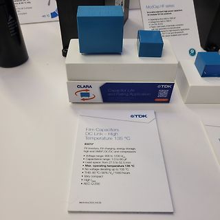
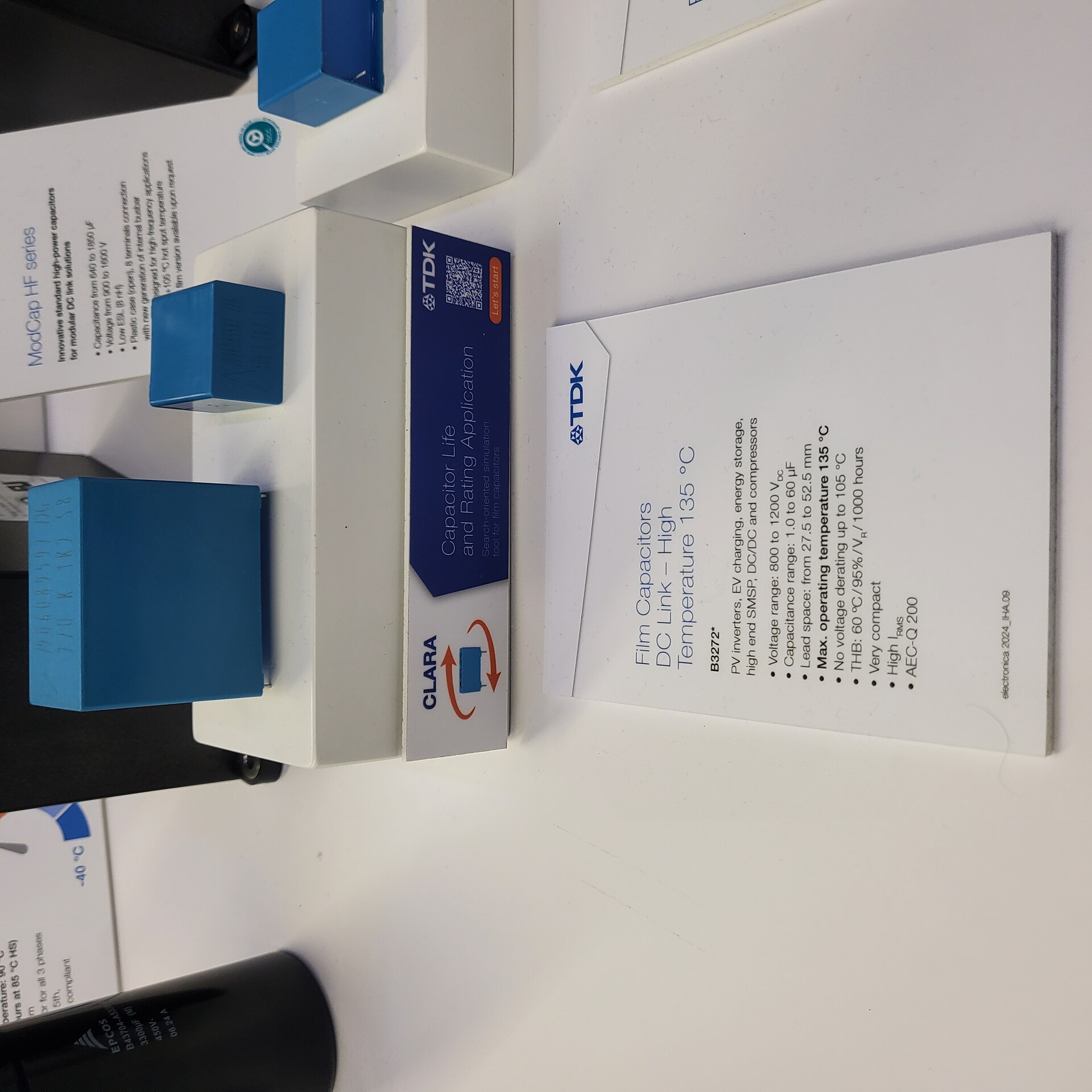
CLARA Capacitor Life and Rating Application
TDK
Film Capacitors
DC Link – High Temperature 135 °C
B3272*
PV inverters, EV charging, energy storage,
high end SMSP, DC/DC and compressors
Voltage range: 800 to 1200 V_DC
Capacitance range: 1.0 to 60 µF
Lead space: from 27.5 to 52.5 mm
Max. operating temperature 135 °C
No voltage derating up to 105 °C
THB: 60 °C / 95% / 1000 hours
Very compact
High Irms
AEC-Q 200
Hinnerk P. schrieb im Beitrag #7777931: > Die 135V sind durch die Belastung mit dem Rechtecksignal überlagert. zeig mal ein Bild
sein. Wenn die Rs 2059/2060 immer noch 2.4k haben wäre der maximal mögliche Strom 56mA, wenn die 135V stabil sind. Sind sie das? Wenn man Deine 8-12V nach dem R2066/R2067 abzeiht, also nur ca. 125V zur Verfügung stehen, hast Du nur noch 52mA als max. Strom. Davon hast Du ja schon 43mA gemessen

 Bild
Bild
 Bild
Bild
 Bild
Bild
 Bild
Bild