-
PDF
Visio_120-22-R2C.pdf
Gebäudeautomation, Kläranlagen, Isolation: durch Relais Umwelttechnik, Heizungssteuerung, Maximaler Strom: 5 A max (resistiv) Zugangskontrolle, Kleinmaschinensteuerung 1 A max (induktiv) • Optionen: GSM-Modem Kit, analoge und digitale Maximale Frequenz: 0,5 Hz Erweiterungsmodule • Analoge Eingänge: 2 analoge Eingänge
in „MINI-SPS mit AVR od. ARM“ · Mikrocontroller und Digitale Elektronik ·
-
PDF
PSP108_datenblatt_Co2_.pdf
UART, Modbus protocol (Note 5). Direction control pin for direct Serial communication connection to RS485 receiver integrated circuit. 8500/6500 ppm normally conducting Alarmstateopen max 100 mA. Transistor open at CO 2 Alarm output, Open Collector High, OR Power Low, OR at Sensor CO2 Failure PWM output
in „MSP430 MODBUS“ · Mikrocontroller und Digitale Elektronik ·
-
 Bild
Bild
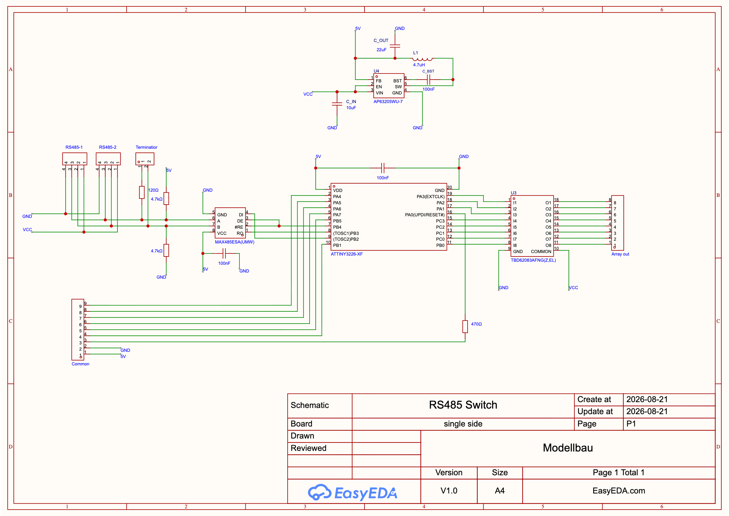
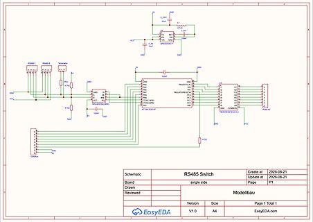
Schaltplan eines RS485-Switches
RS485-1 RS485-2 Terminator 120Ω 4.7kΩ GND VCC 5V 100nF U4 22uF L1 4.7uH C_OUT BST FB VIN GND C_IN 10uF AP6320WUJ-7 VCC GND 5V 100nF U3 PA3(EXT) PA2 PA1 PA0(UPDI/RESET) PC3 PC2 PC1 PC0 PB1 PB0 ATTINY328F-X MAX485ESA(UMW) 4.7kΩ 5V 100nF GND 47Ω Array out COMMON VCC Schematic RS485 Switch Create at 2026-08-21 Update at 2026-08-21 Board single side Page P1 Drawn Modellbau Page 1 Total 1 Version V1.0 Size A4
in „Feedback gesucht: I2C-Bussystem für LEDs, Mini-Motoren & Servos im RC-Schiff (ESP32)“ · Mikrocontroller und Digitale Elektronik · · Schaltpläne
-
 Bild
Bild
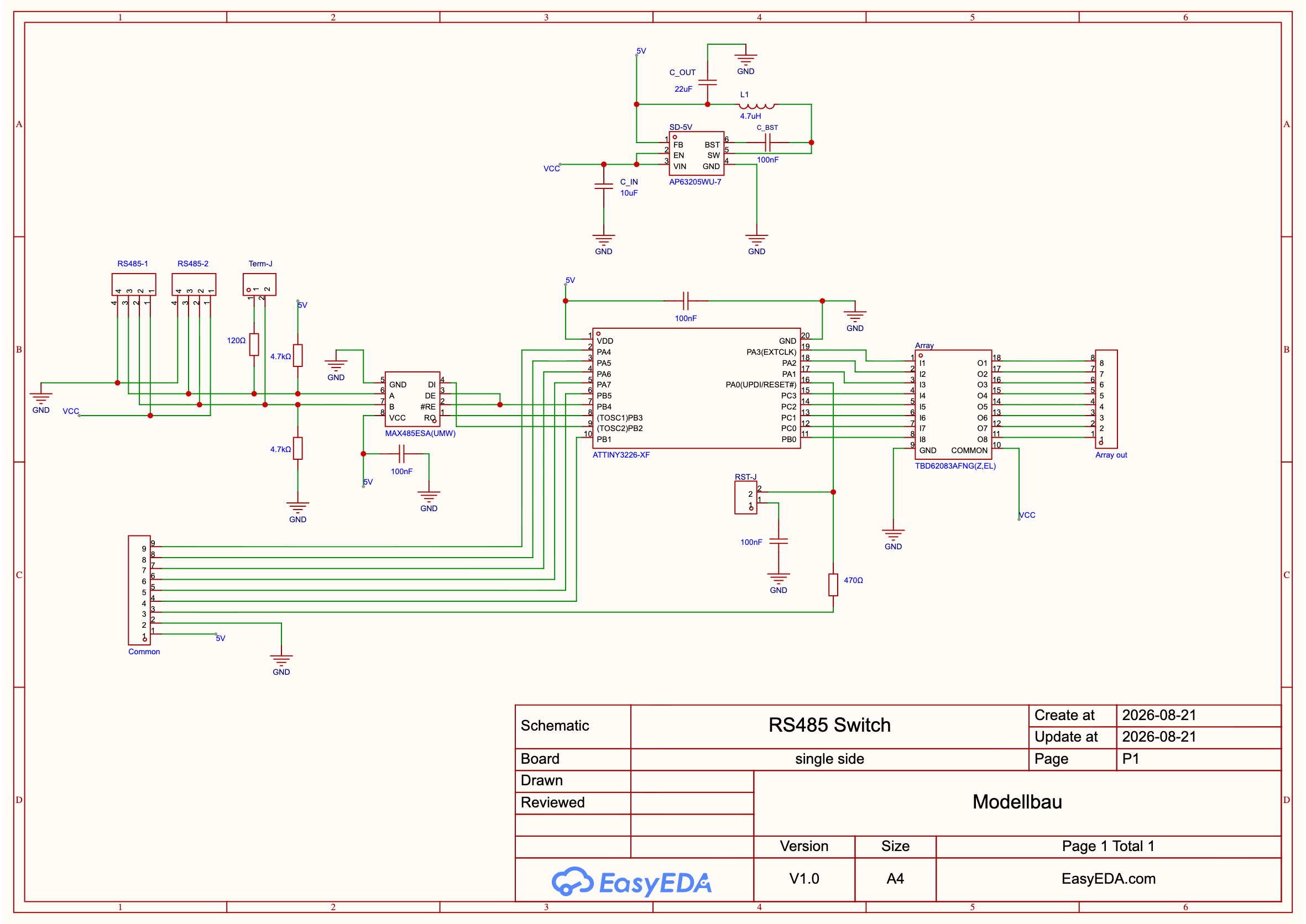
Schaltplan eines RS485-Switches mit ATtiny3226-Mikrocontroller
RS485-1 RS485-2 Term-J 120Ω 5V 4.7k GND DI DE RE GND VCC MAX485ESA(UMW) PB0 PB1 PB2 PB3 PB4 PB5 PB6 PB7 PA0(RESET) PA3(EXTINT) VDD GND 5V 100nF GND 5V C_OUT 22uF L1 4.7uH FB BST 100nF VIN GND SD-5V C_IN 10uF
in „Feedback gesucht: I2C-Bussystem für LEDs, Mini-Motoren & Servos im RC-Schiff (ESP32)“ · Mikrocontroller und Digitale Elektronik · · Schaltpläne

-
PDF
SN75176B_TEX.pdf
V OD2 with a 100-load is either 1OD1Vor 2 V, whichever is greater. NOTES: 3. See ANSI Standard RS-485 Figure 3.5, Test Termination Measurement 2. 4. This applies for both power on and off; refer to ANSI Standard RS-485 for exact conditions. The EIA/TIA-422-B limit does not apply for a combined driver
in „Welcher Bus für mein Projekt?“ · Mikrocontroller und Digitale Elektronik ·
-
PDF
treiber.pdf
V OD2 with a 100-load is either 1OD1Vor 2 V, whichever is greater. NOTES: 3. See ANSI Standard RS-485 Figure 3.5, Test Termination Measurement 2. 4. This applies for both power on and off; refer to ANSI Standard RS-485 for exact conditions. The EIA/TIA-422-B limit does not apply for a combined driver
in „RS485 mit SN65176B“ · Mikrocontroller und Digitale Elektronik ·
-
PDF
sn75176bd_SMD.pdf
OD2 with a 100-load is either 1OD1Vor 2 V, whichever is greater. NOTES: 4. See ANSI Standard TIA/EIA-485-A, Figure 3.5, Test Termination Measurement 2. 5. This applies for both power on and off; refer to ANSI Standard TIA/EIA-485-A for exact conditions. The TIA/EIA-422-B limit does not apply for a combined
-
PDF
75176B.pdf
OD2 with a 100-load is either 1OD1Vor 2 V, whichever is greater. NOTES: 4. See ANSI Standard TIA/EIA-485-A, Figure 3.5, Test Termination Measurement 2. 5. This applies for both power on and off; refer to ANSI Standard TIA/EIA-485-A for exact conditions. The TIA/EIA-422-B limit does not apply for a combined
-
PDF
SN75176B.pdf
V OD2 with a 100-load is either 1OD1Vor 2 V, whichever is greater. NOTES: 3. See ANSI Standard RS-485 Figure 3.5, Test Termination Measurement 2. 4. This applies for both power on and off; refer to ANSI Standard RS-485 for exact conditions. The EIA/TIA-422-B limit does not apply for a combined driver
in „STM32 UART Kommunikation -> Langsamer uC Tod“ · Mikrocontroller und Digitale Elektronik ·
-
Datei
profibus.c
ifndef TX_IRQ // Ohne Interrupt senden // DEBUG /* TESTPIN_HIGH; TACCTL0 &=~CCIE; // Interrupt aus RS485_TX_EN; uart0_send_data(&data[0], length); // Warten bis letztes Byte gesendet worden ist while (UCA0STAT & UCBUSY); RS485_RX_EN; TACCTL0 = CCIE; // Interrupt ein TAR = 0; TACCR0 = TIMEOUT_MAX_SYN_TIME
-
PDF
ED2015-0544_UM_9_Syn48E_battery_rev1.pdf
Lithium batteries UN 3480 - 12/45 3. GENERAL DESCRIPTION OF THE BATTERY SYSTEM 3.1.Synoptic CAN Open RS485 Customer Diagnostic bus Power supply: 24V bus +BATT -BATT BMM Module supply : 5V Module: 14 cells in series (54V max) Module: 14 cells in series (54V max) Module: 14 cells in series (54V max) Module: 14 cells in series (54V max) 9 modules in series Module: 14 cells in series (54V max) Module: 14 cells in series (54V max) Module: 14 cells in series (54V max) Module: 14 cells in series (54V max) Module: 14 cells in series (54V
in „CAN OPEN CiA Draft Standard 301“ · Mikrocontroller und Digitale Elektronik ·
-
PDF
CH340DS1.PDF
the pins and their functions are the same as common PC DB9 connector, the chips similar with U8 have MAX213/ADM213/SP213/MAX211 etc. U8 and C46/C47/C48/C49/C40 could be removed when realize USB to TTL converter only. The signal lines CH340 Datasheet 8 in the image only RXD、TXD and public ground need connected
in „CH340G meldet sich nicht als serielle Schnittstelle am PC (Windows)“ · Mikrocontroller und Digitale Elektronik ·
-
PDF
CH340_USB_UART.pdf
the pins and their functions are the same as common PC DB9 connector, the chips similar with U8 have MAX213/ADM213/SP213/MAX211 etc. U8 and C46/C47/C48/C49/C40 could be removed when realize USB to TTL converter only. The signal lines in the image only RXD、TXD and public ground need connected, the other
in „FT232 lieferbar?“ · Mikrocontroller und Digitale Elektronik ·
-
PDF
XPort-Pro_IG.pdf
output: CP1 can be driven or read through software control, independent of serial port activity. • RS485 Transmit Enable: In RS485 mode, CP1 is driven by the built-in UART for connection to the transmit enable pin of an RS485 Transceiver. CP2/DTR 7 CP2 can be configured as follows: (Configurable Pin 2)
in „[V] 2St. gebrauchte Lantronix XPORT PRO Module -LAN-Seriell, KLEINEN DEFKTEN , zu Fädeln (beide 8€)“ · Markt ·
-
PDF
XPort-Pro_IG.pdf
output: CP1 can be driven or read through software control, independent of serial port activity. • RS485 Transmit Enable: In RS485 mode, CP1 is driven by the built-in UART for connection to the transmit enable pin of an RS485 Transceiver. CP2/DTR 7 CP2 can be configured as follows: (Configurable Pin 2)
in „[V] 3St. gebrauchte Lantronix XPORT PRO Module -LAN-Seriell MIT KLEINEN DEFKTEN (alle für 15€)“ · Markt ·
-
PDF
XPort-Pro_IG.pdf
output: CP1 can be driven or read through software control, independent of serial port activity. • RS485 Transmit Enable: In RS485 mode, CP1 is driven by the built-in UART for connection to the transmit enable pin of an RS485 Transceiver. CP2/DTR 7 CP2 can be configured as follows: (Configurable Pin 2)
in „[V] 1x gebrauchtes Lantronix XPORT PRO Module -LAN-Seriell Module (13€)“ · Markt ·
-
PDF
349_529-15.pdf
± 5° 5° ¬ 6 30°± 20 16.5 12.5 0.3 A 0.3 A 0.05 A 0.05 A . e . ±1 i ±1 i e m m 7 7 7 ¬ 7 ¬ ±0.2 2 1 max. 2 ¬ 6 1 1 ¬ ¬ 1 max. 24°±1° 1 max. 11 min. 8 min. 56 min. 11 min./19 max. 58 min. 16 * e e t a c i a c b e u o ä e n e e a e h Ma p k b B d s u . . o a A s o g 2 a h e . t e . n e o s s e z r A k o
in „Wie entsteht das Sinusförmige Signal eines Drehgebers/ Vermutung“ · Offtopic ·
-
Datei
main.c
stdlib.h> #include <stdint.h> #include "panelfunktionen.h" #include "sensorfunktionen.h" #include "RS485.h" /* 9600 baud */ #define BAUD1 9600UL // Baudrate #define UBRR_VAL_UART ((F_CPU+BAUD1*8)/(BAUD1*16)-1) // clever runden #define SLAVEADRESS 1 //Sensordefinition************************************
in „Master und 3 Slaves, Kommunikation läuft nicht rund Bitte um Hilfe“ · Mikrocontroller und Digitale Elektronik ·
-
PDF
adm2490e.pdf
High Speed, ESD-Protected, Full-Duplex, iCoupler Isolated RS-485 Transceiver ADM2490E FEATURES FUNCTIONAL BLOCK DIAGRAM Isolated,full-duplexRS-485/RS-422transceiver VDD1 VDD2 ±8kVESD protectiononRS-485input/outputpins 16Mbpsdata rate ADM2490E Complieswith ANSITIA/EIA-485-A-1998and Y ISO8482:1987(E) I TxD A Z Suitable for 5V or 3V operation (V DD1) O Highcommon-modetransient immunity:>25kV/μs I I Receiverhas open-circuit,fail-safe design A A 32nodesonthebus L RxD G B
in „RS485 Baustein ohne 12V einspeisung?“ · Mikrocontroller und Digitale Elektronik ·
-
PDF
spi_differential_apnote_ti.pdf
rejects the induced noise. Differential signaling can be accomplished with TIA/EIA-422 (RS-422), TIA/EIA-485 (RS-485), TIA/EIA-644 (LVDS), or TIA/EIA-899 (M-LVDS) standard compliant interface circuits. Choosing a differential interface standard is application dependent, since there are different benefits with
in „SPI mit (M-)LVDS-Technik - Bitte um Konzeptbewertung“ · Mikrocontroller und Digitale Elektronik ·
-
PDF
DCM230_Stromzaehler.pdf
(default), 200mS Pulse output indicate Total kWh/ import kWh/ export kWh Display LCD with backlit Max. Reading 999999.9kWh Weight 220g Standard GB/T 33708-2017 Accuracy class 1 (max.1%measurementdeviation) Unit Characteristics The Unit can measure and display: ⚫ voltage ⚫ Currents ⚫ Power ⚫ Active energy
in „DC Stromzähler mit Mess-Shunt zählt nicht“ · Analoge Elektronik und Schaltungstechnik ·
-
PDF
Peg_v7b.pdf
- PEG-Vorlesung WS2000/2001 - Institut für In52rmatik - FU Berlin 13 Temperaturüberwachung mit dem MAX1619 Liers - PEG-Vorlesung WS2000/2001 - Institut für In53rmatik - FU Berlin RS-232 und IRDA mit dem MAX3130 Liers - PEG-Vorlesung WS2000/2001 - Institut für In54rmatik - FU Berlin 14 RS-485 mit dem MAX3291 Liers - PEG-Vorlesung WS2000/2001 - Institut für In55rmatik - FU Berlin RS-485 Netzwerk mit dem MAX3291 Liers - PEG-Vorlesung WS2000/2001 - Institut für In56rmatik - FU Berlin 15 AD-Wandler MAX725
in „Einfache Verstaerkerschaltung mit OP“ · Analoge Elektronik und Schaltungstechnik ·
-
PDF
RS485_Dimmer_Controller_1.3.sch.pdf
XCK/T0) 11 DE SV1-2 VCC PD5(T1) A C1 C2 PD6(AIN0) 12 4 DI PD7(AIN1) 13 22p 22p PB0(ICP) 14 . e b s MAX485 PB1(OC1A) 15 g 3 m 1r Dt GND PB2(SS/OC1B) 16 SV1-10 r E i Ee Et PB3(MOSI/OC2) 17 ISP-1 P 1 2 C6 L D LB LS GND GND PB4(MISO) 18 ISP-9 3 19 S 100n PB5(SCK) ISP-7 3 4 7 k 5 k 6 k IC2 R 1 R 1 R 1 GND
in „Welche Taster für Eigenbau-Hausbus geeignet“ · Haus & Smart Home ·
-
Datei
kwb13.ino
bestimmt nicht fehlerfrei läuft aber seit einer Weile stabil // Hardware // Webmos d1 mini Pro + HER MAX485 module // Stromversorgung über Kessel 24V-> 7800 Spannungsregler // Neben den Kesselwerten werden noch Brennerlaufzeit Gesamtenergie // berechnet mit der der Pelletverbrauch bestimmt werden kann
-
Datei
rs485.c
#include "rs485.h" const uint16_t baud = baudrate; static uint8_t parity_error = 0; // muss den wert über die funktion hinaus behalten void UART_init(void) { // Set the USART baudrate registers UBRRH = (uint8_t)baud
in „RS485 geht nicht“ · Mikrocontroller und Digitale Elektronik ·
-
PDF
Schematic_Prints.pdf
IN OUT 2 1 3 USB 5V 2 2 C1 C2 GND C3 C4 Pwr 4.7U/35 100n 3 100n 4.7U/35 A +5 A +5 1 2 R1 LED 1k B RS485 +12 C6 B 1 VCC RS-485 4-wire +12 Bus 2 8 100n 1 2 USB R 7 3 4 1 (GND) 5 6 (CTS#) 6 (RX1) (RX2) 2 (VCC) USB 5V 3 5 (TX1) 7 8 (TX2) 3 (TXD) D 9 10 4 (RXD) 4 Wannenstecker 10-Pin 5 (RTS#) GND 6 MAX488CPA
in „Bus an Atmega32 funktioniert nicht“ · Mikrocontroller und Digitale Elektronik ·
-
Datei
main.c
UBRR_BAUD_BUS ((SYSCLK/(16*BAUD_BUS))-1) // 9 Bit Datenübertragung void delay_ms(unsigned int ms); void RS485_TX( unsigned int data ) { PORTD |= (1<<PD2); // High Max senden while ( !( UCSRA & (1<<UDRE)) ) ; UDR = data; PORTD &= ~(1<<PD2); // Low Max empfangen } void uart_init(void) { UBRRH = (unsigned char
in „MAX 485 Problem beim umschalten“ · Mikrocontroller und Digitale Elektronik ·
-
Datei
profibus.c
0; cnt < DIAG_DATA_SIZE; cnt++) { Diag_Data[cnt] = 0x00; } #endif new_data=0; // AVR Timer init RS485_RX_EN; UCSRB |= (1<<RXCIE); DDRD |= 0xf0; // Debug outputs. PORTD |= 0x80; OCR1A = TIMEOUT_MAX_SYN_TIME; TIMER1_RUN; // Start counting. TIMER2_RUN; TIMSK |= 0x04; // Enable interrupt on Timer1 overflow
-
Datei
main.c
UBRR_BAUD_BUS ((SYSCLK/(16*BAUD_BUS))-1) // 9 Bit Datenübertragung void delay_ms(unsigned int ms); void RS485_TX( unsigned int data ) { while ( !( UCSRA & (1<<UDRE)) ) ; UDR = data; } void uart_init(void) { UBRRH = (unsigned char) (UBRR_BAUD_BUS>>8); UBRRL = (unsigned char) UBRR_BAUD_BUS; UCSRB = (1<<RXCIE)
in „MAX 485 Problem beim umschalten“ · Mikrocontroller und Digitale Elektronik ·
-
Datei
main.c
UBRR_BAUD_BUS ((SYSCLK/(16*BAUD_BUS))-1) // 9 Bit Datenübertragung void delay_ms(unsigned int ms); void RS485_TX( unsigned int data ) { PORTD |= (1<<PD2); // High Max senden while ( !( UCSRA & (1<<UDRE)) ) ; UDR = data; // Warten bis alles gesendet wurde while ( !(UCSRA & (1<<TXC)) ) ; UCSRA = (1<<TXC); PORTD
in „MAX 485 Problem beim umschalten“ · Mikrocontroller und Digitale Elektronik ·
-
Datei
main.c
u_receive_string[i] = UDR; //lcd_putc(i); // Sendstring: 01 10 01 00 01 04 00 00 30 18 if (i==5) { receive_max = u_receive_string[i] +5; //if((u_receive_string[i] & 0x10 )== 0x10) } if(i == receive_max) { u_rx_start=0; u_r_c = receive_max; //USART_Transmit('Z'); } else { i++; u_rx_start = i; } } } ISR(TIMER1
in „Master und 3 Slaves, Kommunikation läuft nicht rund Bitte um Hilfe“ · Mikrocontroller und Digitale Elektronik ·
-
PDF
MF5DS.pdf
Serial COMS-TTL 22 NC No Connect 23 TX22 RF Signal Output 1 Supply Voltage 5VDC Operating Current Max. 80mA 24 TVSS RF Signal GND 25 TX11 RF Signal Output 2 Size Dimensions. L36 x W26 x H6 mm 26 NC No Connect Temperature Range -10°C ~ 60°C 27 NC No Connect 28 VCC Power 5VDC Note: ISP Enable when ISP
in „MiFare Reader Bluetooth oder Ethernet“ · HF, Funk und Felder ·
-
PDF
Bauteile.pdf
0,54mΩ NKanal 112 21 74xxxx 74HC374ADW SMD 8BitFlipFlop 24 22 Optokoppler BRT23H Pin 15 23 Treiber ST485BDR RS485Treiber 17 24 74xxxx 74HCT161 SMD Counter 30 25 Treiber UCC3801 RS485Treiber 69 26 Treiber DS8921AM 9 27 EEPROM 93LC46A 1KSerielEEPROM 50 28 Mos-Fet IRL2910PBF 20V 61A 132mΩ TO-220AB NKanalMosFET
in „Elektronik Bauteile Neuwertig , meist Leistungselektronik“ · Markt ·
-
Datei
profibus.c
ifndef TX_IRQ // Ohne Interrupt senden // DEBUG /* TESTPIN_HIGH; TACCTL0 &=~CCIE; // Interrupt aus RS485_TX_EN; uart0_send_data(&data[0], length); // Warten bis letztes Byte gesendet worden ist while (UCA0STAT & UCBUSY); RS485_RX_EN; TACCTL0 = CCIE; // Interrupt ein TAR = 0; TACCR0 = TIMEOUT_MAX_SYN_TIME
-
PDF
DS_FT232BL_BQ.pdf
7/8 bit Parallel to Serial and Serial to Parallel conversion of the data on the RS232 (RS422 and RS485) interface. Control signals supported by the UART include RTS, CTS, DTR, DSR, DCD and RI. The UART provides a transmitter enable control signal (TXDEN) to assist with interfacing to RS485 transceivers
-
PDF
SPI-Logger.pdf
Umschaltung RS232 / RS485 / USB C n FT232H & SPI USB <-> Seriell C 3 0 V V C 1 3 + C 0 0 C 5 0 C 1 C 1 C20 C21 V C 1 GND 100n 100n C GND GND C4 C6 C n 1 1 GND V 8 GND V 2 0 IC7 100n LTC1387 3 1 1 100n 27pF 27pF D C 1 16 30 12MHz
in „FT232H - unknown device“ · Mikrocontroller und Digitale Elektronik ·
-
Datei
kwb23.ino
bestimmt nicht fehlerfrei läuft aber seit einer Weile stabil // Hardware // Webmos d1 mini Pro + HER MAX485 module // Stromversorgung über Kessel 24V 7800 Spannungsregler // Neben den Kesselwerten werden nich Brennerlaufzeit Gesamtenergie // berechnet mit der der Pelletverbrauch bestimmt werden kann (ca
-
PDF
bedienungsanleitung-1325476-controllino-mega-100-200-00-sps-steuerungsmodul-12-vdc-24-vdc.pdf
Wannenstiftleisten und Mikrocontroller nachsehen. CONTROLLINO Bedienungsanleitung Seite 19 (31) RS485 Schnittstelle Die CONTROLLINO Steuerungen MAXI und MEGA besitzen eine RS485 Schnittstelle vom Typ SN65HVD08, mit der Sie mit anderen RS485 Geräten kommunizieren können. Die RS-485 ist ein Schnittstellen-Standard
in „Diode kühlen, wie?“ · Analoge Elektronik und Schaltungstechnik ·
-
 Bild
Bild
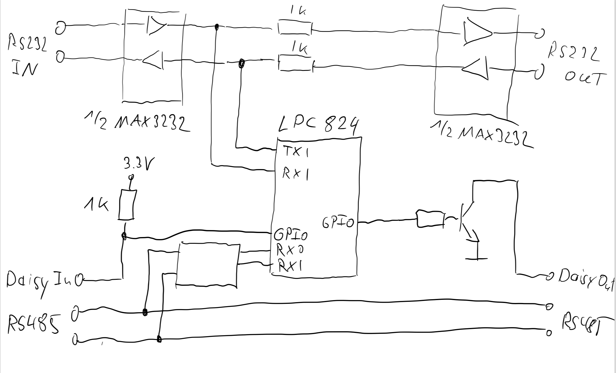
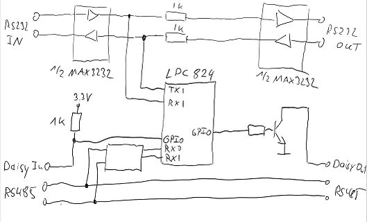
Handgezeichneter Schaltplan mit LPC 824 und RS232/RS485 Schnittstellen
RS232 IN, 1/2 MAX3232, 1k, LPC 824, TX1, RX1, 3.3V, 1k, GPIO, RX0, RX1, Daisy In, RS485, Daisy Out, RS485, 1/2 MAX3232
in „9x RS232 anbinden / Denkanstoß zur Entwicklung eines RS232 digitalen Umschaltt. Hilfe benötigt“ · Mikrocontroller und Digitale Elektronik · · Diagramme
-
 Bild
Bild
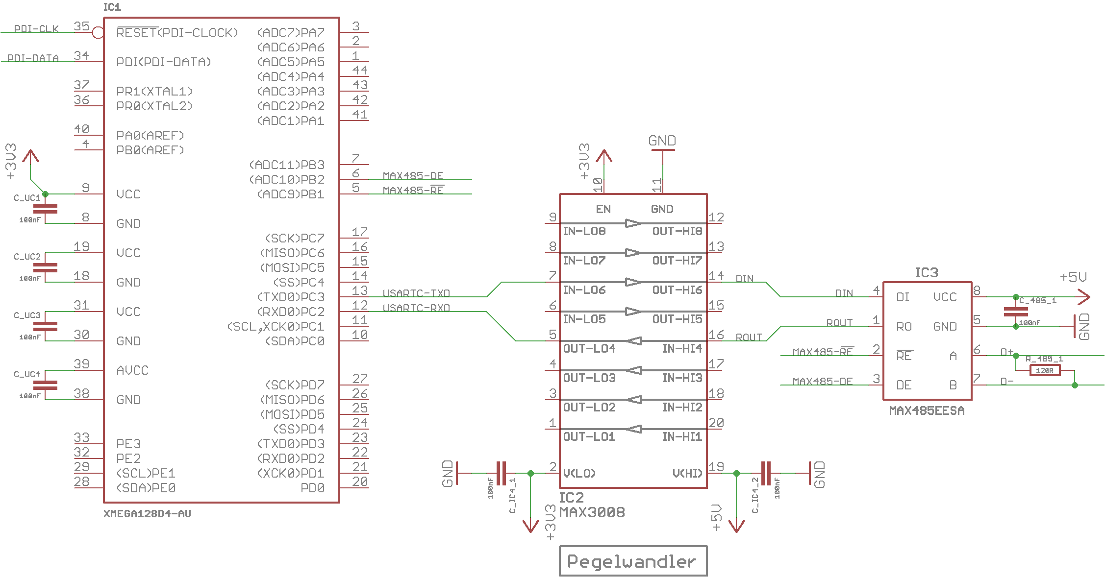
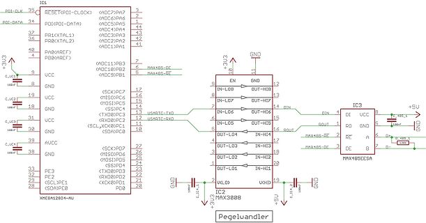
Schaltplan mit Mikrocontroller und Pegelwandler
IC1 XMEGA128D4-AU, IC2 MAX3008, IC3 MAX485EESA, Pegelwandler, 100nF, +3U3, +5U, GND, PDI-DATA, PDI-CLK, RESET, ADC7 bis ADC1, PB3 bis PB0, PC7 bis PC0, PD6 bis PD0, UART, RS485
in „MAX485 - Kommunikations- und Pegelprobleme“ · Mikrocontroller und Digitale Elektronik · · Schaltpläne
-
PDF
datasheet_SC16IS750.pdf
receiving. 0: receiver is enabled 1: receiver is disabled 0 9-BIT MODE Enable 9-bit or Multidrop mode (RS-485). 0: normal RS-232 mode 1: enables RS-485 mode [1] For SC16IS760 only. 9. RS-485 features 9.1 Auto RS-485 RTS control Normally the RTS pin is controlled by MCR bit 1, or if hardware flow control is enabled
in „UART_Initialisierung“ · Mikrocontroller und Digitale Elektronik ·
-
PDF
ds.pdf
mit allen Klemmen in seinem Stromkreis. Ein Stromkreis übergreifende Ansteuerung erfolgt über den dS485 Bus. Der dS485 Bus basiert auf der TIA/RS485Technologie. Hierzu müssen alle digitaISTROM-Meter und digitaISTROM-Server über eine zweiadrige Kommunikationsleitung miteinander verbunden sein. digitaISTROM-Filter
-
 Bild
Bild
Werbeaufsteller für Sferalabs Strato Pi Max Edge Controller
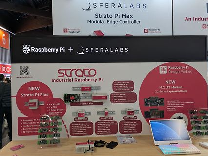
SFERALABS Strato Pi Max Modular Edge Controller Raspberry Pi Design Partner Raspberry Pi + SFERALABS NEW Strato Pi Plus 4 x RS-485 1 x CAN Relay Output Optional Fan Raspberry Pi 4 GPIO Ethernet Wi-Fi BLE Hardware Watchdog Secure Element 10-50Vdc Power Supply Strato Pi CAN Raspberry Pi 36 or 4 Ethernet, Wi-Fi, BLE, CAN, RS-485 1 Relay Output Secure Element, RTC 65Vdc Power Supply Strato Pi CM Raspberry Pi CM4 or CM5 Dual SD card Strato Pi CM Dual Ethernet, RS-485 Ethernet, Wi-Fi, BLE Secure Element, RTC 65Vdc Power Supply
in „EmbeddedWorld 2026, Tag 3 – Messtechnik, Software und mehr“ · Mikrocontroller und Digitale Elektronik · · Fotos
-
PDF
RS485_RS232.pdf
T2IN Western, Print 2 13 12 7 R1IN R1OUT 3 8 R2IN R2OUT 9 R K Buchsenplatine 8 4 BU4 4 GND 1 9 15 MAX232 6 5 Um- IC1 2 D1 1 7 Print-Buchse +5V S1 schaltung S2 4 R 6 C8 Sub-D, 9polig 1N4148 2 T A 7 3 PC vollduplex 3 /RE B 220p 8 TE ker 4 auto halbduplex 9 75176 5 5 0 8 0 7 0 6 6 Sub-D, 9polig R 1 R 1
in „Brauche Hilfe bei Projektarbeit“ · Mikrocontroller und Digitale Elektronik ·
-
PDF
XLampXML2.pdf
equipment. Profile Feature Lead-Based Solder Lead-Free Solder Average Ramp-Up Rate (Ts to Tp) 3 °C/second max. 3 °C/second max. max Preheat: Temperature Min (Ts ) 100 °C 150 °C min Preheat: Temperature Max (Tsmax) 150 °C 200 °C Preheat: Time (tsmino tmax) 60-120 seconds 60-180 seconds Time Maintained Above:
in „Li Akku effizient in WLED endladen“ · Analoge Elektronik und Schaltungstechnik ·
-
PDF
ST500Datenblatt_v2.2.pdf
Drehmoment ProgrammierbareAusgänge: 2 0V - 10V DC Erhöhung bei Automatische Erhöhung bei Spannungsbereich: max.5mA niedrigen Frequenzen (1Hz) Schweranlauf im Manuelle Drehmomenterhöhung Strombereich: 0mA - 20mA U/f-Modus: einstellbar (0,1% - 30%) max.Last 250Ω Reaktionszeit: <40ms beiVektorregelung Anzahl Funktionen: 16 Anlaufmoment: 150% ab 0,5Hz beiVektorreg. Kommunikation RS485 / Modbus Einschaltbare Begrenzung des Integrierte RS485-Schnittstelle zurAnsteuerung per Mod- Begrenzung: Moments,um Überstrom zu bus/RTU-Protokoll.Optional erhältlicher Bluetooth-Adap- vermeiden ter
in „Drehstrommotor an FU bringt nicht volle Leistung?“ · Analoge Elektronik und Schaltungstechnik ·
-
PDF
DS_FT232H.pdf
Feature Process material) Solder Process (green material) Average Ramp Up Rate (T ts T )p 3°C / second Max. 3°C / Second Max. Preheat - Temperature Min (T Min.) 150°C 100°C s - Temperature Max (T sax.) 200°C 150°C - Time (tsMin to s Max) 60 to 120 seconds 60 to 120 seconds Time Maintained Above Critical
-
Datei
PLC-LOX.txt
define oneWireVsensByte 13 #define oneWireDS18B20Byte 40 #define inputPacketBufferSize UDP_TX_PACKET_MAX_SIZE char inputPacketBuffer[UDP_TX_PACKET_MAX_SIZE]; #define outputPacketBufferSize 100 char outputPacketBuffer[outputPacketBufferSize]; EthernetUDP udpRecv; EthernetUDP udpSend; #define oneWireCycle
in „1 Wire auf 2 GPIO pins“ · Mikrocontroller und Digitale Elektronik ·
-
 Bild
Bild
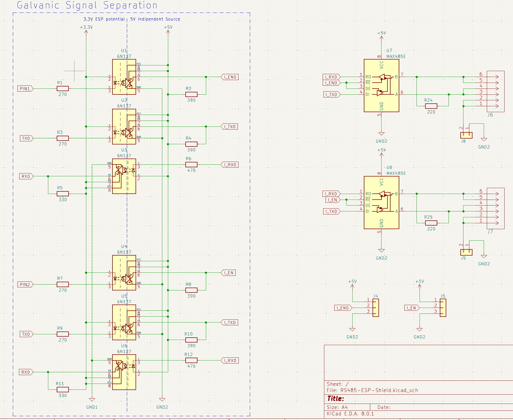
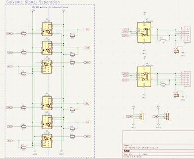
Schaltplan zur galvanischen Signalabtrennung
270 U1 6N137 R2 390 TX0 R3 270 U2 6N137 R4 390 RX0 R5 330 U3 6N137 R6 470 I_EN0 I_TX0 I_RX0 +5V U7 MAX485E R24 220 J6 GND2 U8 MAX485E R25 220 J7 PIN2 R7 270 U4 6N137 R8 390 TX0 R9 270 U5 6N137 R10 390 RX0 R11 330 U6 6N137 R12 470 I_EN I_TX0 I_RX0 GND1 GND2 J4 J5 KiCad E.D.A. 8.0.1
in „ESP32 Max485 und 6N137 brennt ab“ · Mikrocontroller und Digitale Elektronik · · Schaltpläne
-
PDF
RS485_ISO.pdf
01 02 03 04 05 U$1 A A VIN+ VOUT+ + VIN+VOUT+ V VCC/2 VIN- VOUT- VIN- VOUT- DCDC GND AGND RS485-B / / / / C C C C V+ V+ V+ 2 V V V V 1 D1 X V+ V+ V+ X3-1 + C3 C1 C2 +C4 4 B 47µF/10V 100n IC1 100n 47µF/10V 2 - B GND X3-2 D 4 IC2 A GND GND GND 1 16 0 1 B VDD1 VDD2 1 2 R 7 10 AGND AGND RO 1 VE1 VE2
in „[V] PCB f. galv. getrennten RS485 umsetzer mit ADUM1301“ · Markt ·