mal N, mit der Amplitude gehen die frequenz schnell abnehmend. Wir hatten solche Netzteile fuer 200 Volt, an 3 Ohm Last, 12 kW. Diese Netzteile hatten die Thyristor Stufen auf 3V oberhalb Ausgangsspannung geregelt. Nachher kam eine Linear Endstufe, welche mit diesen 3V Abfall alle Rippel, resp Harmonischen
verbleibende Strom ist sicher unter 1mA und wird vom Spannungsteiler R1..R4 : R15+R16 sicher nach V_ref abgeleitet. Mein Nachbau nutzt nur die Vorregelung und einen MAA723 als Hauptregler. Die negative Spannung entfällt komplett (ich brauche keine Einstellung bis 0V runter). Schaltung müßte ich noch
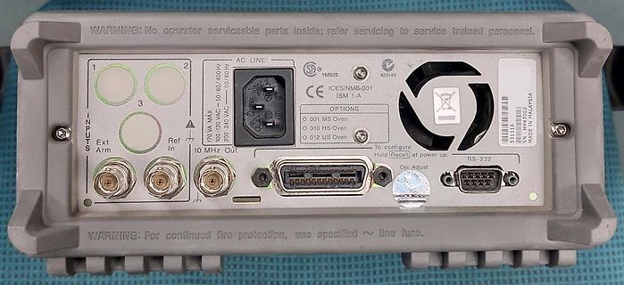
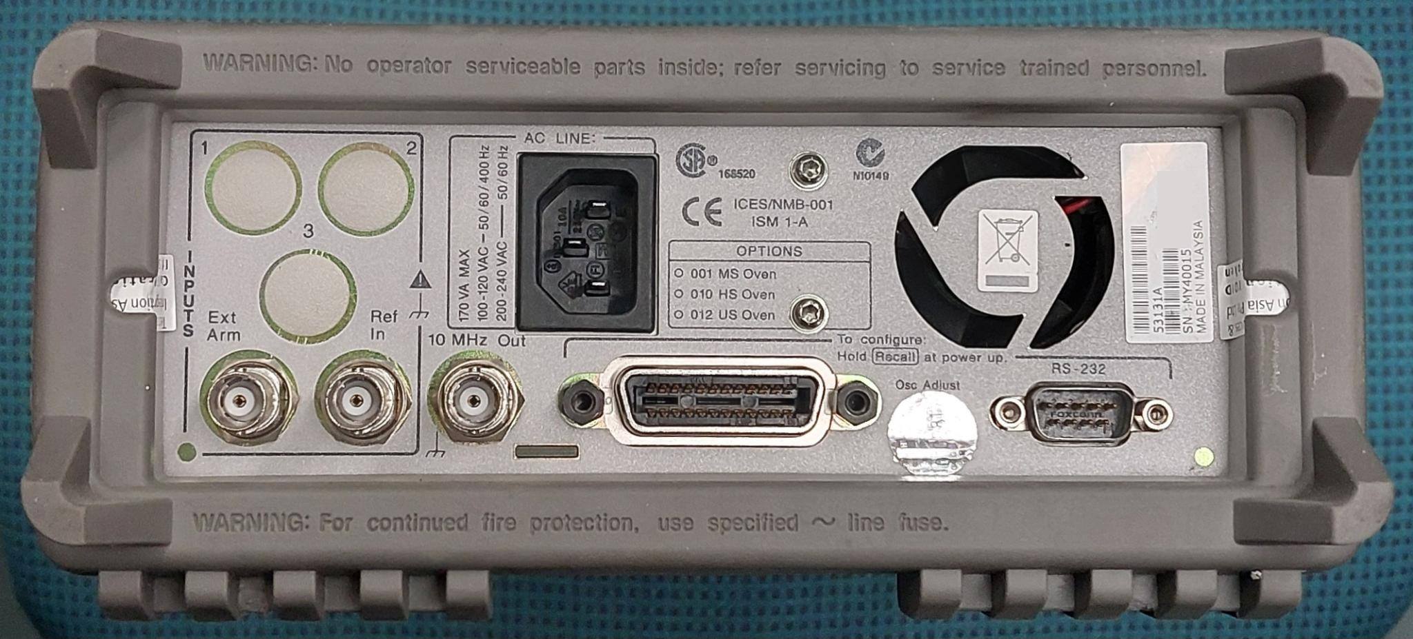
WARNING: No operator serviceable parts inside; refer servicing to service trained personnel. 1 2 3 AC LINE: 100-120 VAC 200-240 VAC 50/60 Hz ISM 1-A CE ICES/NMB-001 168520 N10149 OPTIONS 0 001 MS Oven 0 010 HS Oven 0 012 US Oven INPUTS Ext Arm Ref In
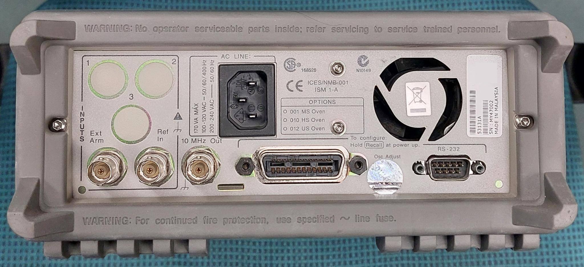
WARNING: No operator serviceable parts inside; refer servicing to service trained personnel. 1 2 3 INPUTS Ext S Arm Ref In 10 MHz Out 170 VA MAX 100-120 VAC ~ 200-240 VAC 50/60 Hz AC LINE CE ICES/NMB-001 ISM 1-A OPTIONS 0 001 MS Oven 0 010 HS Oven 0
Figure 1 60 — — Write data hold time t ns Figure 1 15 — — HE Read data delay time DDRE ns Figure 1 — — 200 Read data hold time t ns Figure 1 5 — — DHRE Table 46 High-Speed Write Mode (HWM=1) (Vcc = 2.2 to 2.4 V) Item Symbol Unit Test Condition Min Typ Max Write CYCE ns Figure 1 200 — — Enable cycle time
nötig > sein, ... Das rechne noch mal nach bzw. vor. Selbst ein LEO liegt eigentlich immer über 200 km hoch. Was denkst du, wie groß die Antennen sein müssten, damit bei 11 GHz die durch 30 m Abstand verursachte Parallaxe eine Rolle spielt? Außerdem geht es wohl nur um EINE Schüssel.
9.347 C 0.170 0.180 4.318 4.572 P D 0.026 0.036 0.660 0.914 J E 0.045 0.055 1.143 1.397 N F 0.051 REF 1.295 REF D R G 0.100 BSC 2.540 BSC 0.010 (0.254) M T H 0.539 0.579 13.691 14.707 J 0.125 MAX 3.175 MAX G K 0.050 REF 1.270 REF L 0.000 0.010 0.000 0.254 M 0.088 0.102 2.235 2.591 N 0.018 0.026 0.457 0.660 P 0.058 0.078 1.473 1.981 R 5 REF 5 REF C S 0.116 REF 2.946 REF U 0.200 MIN 5.080 MIN V 0.250 MIN 6.350 MIN http://onsemi.com 10 LM317 Notes http://onsemi.com 11 LM317 ON Semiconductor and are trademarks of Semiconductor Components
temperature coefficient 2 3 R = R eA + B T + C T + D T (1) T = temperature deviation, T ref –1 then: T = ---------- T = A + B ln------+-C ln 2----+ D--ln3--------- (2) TCR R 1 1 R ref 1 Rref 1 R ref The temperature tolerances are plotted in the graphs on the previous page. where: A, B
applied None Current I None R ∆ C ≤ ±20% of initial measured value ≤ ±20% of initial measured value DF ≤ 200% of the initial specified value ≤ 200% of the initial specified value Leakage Current ≤ the initial specified value ≤ the initial specified value Pre‐treatment for measurements shall be Comment conducted
) TJ= 25°C V 500 A VQ= 0 V m T = 125°C ( E J T 600 G 400 E T R L U V 300 C400 P T = 25°C T O J P R 200 T , O D , 200 V 100 IQ 0 0 0 100 200 300 400 0 10 20 30 40 50 IQ, OUTPUT CURRENT (mA) VI, INPUT VOLTAGE (V) Figure 16. Dropout Voltage vs. Figure 17. Maximum Output Current vs. Output Current Input
RMIIInterface 10.4.4 Port 2 RMII Interface Transmit Timing Symbol Parameter Min. Typ. Max. Unit T1 RMII REF_CLK Period - 20 - ns T2 P2_TXE,P2_TXD1~0 to REF_CLK 8 ns Rising Output Delay 10.4.5 Port 2 RMII Interface Receive Timing Symbol Parameter Min. Typ. Max. Unit T1 RMII REF_CLK Period - 20 - ns T2 CRS_DV, P2_RXD to REF_CLK Setup Time 4 - - ns T3 CRS_DV, P2_RXD1~0 to REF_CLK Hold Time 2 - - ns Preliminarydatasheet 99 DM8603-12-DS-P01 November8,2010 Downloaded from Elcodis.com electronic components distributor DM8603
Map is programmable priority queue is transmitted first. The next too. In addition, User can only refer to most highest-priority queue is work until last queue empties, significant 3-bit of the ToS field optionally, see bit 7 of and so on. This feature can be set in bit 5 of register register 53h. 6Dh
between devices, tie one of the substrate pins (Pin 4 or Pin 11) to the most negative circuit potential. REF IOUT = 2REF ) Note that Pin 4 and Pin 11 are internally connected. Q1 ApplicationsCurrentSources MAT14 can be used to implement a variety of high impedance current mirrors as shown in Figure 15, Figure
PARAMETER TEST CONDITIONS MIN TYP MAX UNIT SYSTEM PERFORMANCE Zero Input Reading V = 0.0V, full scale = 200mV -000.0 000.0 +000.0 Digital IN Reading Stability (Last Digit) (ICL7107S Only) Fixed input voltage (Note 11) -000.0 000.0 +000.0 Digital Reading Ratiometric Reading VlN = VREF, REF = 100mV 999 999
3000 I2000 20,000 A T I10,000 TJ=150⋅C N1000 A R T 5000 U N C 500 R 2000 25⋅C A U N 300 C 1000 I C – 200 , 500 L T =25⋅C F M 100 C h S VCE =3.0Vdc 200 –55⋅C V =3.0Vdc E IC=5.0Adc CE h 100 50 50 30 0.01 0.02 0.05 0.1 0.2 0.5 1.0 2.0 5.0 10 103 104 10 106 I ,COLLECTORCURRENT(AMP) f,FREQUENCY(Hz) C Figure
Ausgangsspannung ändert sich nicht. Also, der TK-Wert der Metallfilm Widerstände, meist zwischen 50 bis 200ppm liegend und die Offset Temperaturabhängigkeit des OPVs. Im Temperaturbereich von 20-30 C sollte es aber stabil genug sein. Ohne hochauflösendes Strom-Messgerät wirst Du wahrscheinlich die Temperaturabhängigkeit
auszuarbeiten. https://www.amazon.ca/Sunxeke-Breadboard-Assortment-Flexible-Different/dp/B09NCYWK11/ref=asc_df_B09NCYWK11? https://www.amazon.ca/YDELEKS-Resistor-Component-Bending-Forming/dp/B09CLJG9YS/ref=sr_1_19? Die U/I Umwandel-Schaltung funktioniert unbedingt. Ich habe sie ähnlich oft in vielen
2.7 Power Specifications The drive receives DC power (+5V) through a native SATA power connector (refer to Figure3). 2.7.1 Powerconsumption Power requirements for the drives are listed in the table in Table4.Typical power measurements are based on an average of drives tested, under nominal conditions
circuits Automotive electronics Tape packaging Capacitors with d 16 mm are also available on tape. Refer to page 420 for information on tapes and examples on how to order them. Specifications and characteristics in brief B 41 588 B 43 588 Rated voltage U 10 to 100 V— 160 to 350 V— R Surge voltage U S
REF OUT, UNBAL AES IN and UNBAL AES REF OUT, and the DSP I/O port connector. The TOSLINK optical connectors contain transducers to convert light to a TTL-level electrical signal and electrical to light
this model does represent 1 1.75 A 100 V many such cases. The Machine Model ratings are at 2 3.5 A 200 V lower voltages than those of the Human Body Model, 3 7.0 A 0.85 - 1.2 A 0.29 A 400 V reflecting the more severe environment. ANSI/ESD- 4 14.0 A 800 V S5.2-1994 specifies the following classes of ESD
Califor- erroneous data on data, address and control lines, and nia Micro Devices, Application Note AP-200: GTL + Termina- contribute significantly to clock and signal jitter. tions, Milpitas, CA, 1996) The effective transmission line impedance, Zeff , of the loaded line is The phenomenon that causes this
bereits und weiß es nur noch nicht ;-) Ich wüsste auch nicht, was an einer Heißluftstation für 200€ signifikant besser sein sollte als an einer für 25€. Die Dinger bestehen aus einem in der Drehzahl einstellbarem Gebläse und einer temperaturgeregelten Heizwicklung, mehr nicht. Das ist überhaupt
nicht ok da sie die Teperatur aufgrund die düne schlauch nicht halten kann und bei eingestellte bsp. 200° sie heizt bis auf 300.Ich habe mir sogar ein Neu Heizkolben gekauft und trotzdem funktioniert nicht richtig. Alles andere ist von optionen her mehr als zufriedenstellen.
/www.amazon.de/UGREEN-DH2300-Pers%C3%B6nliche-Einsteigerfreundliches-Heim-NAS-Server/dp/B0FNWWDGSX/ref=sr_1_4 Der Selbstbau mit allem Drum undf Dran (Gehäuse, Netzteil etc.) wird auch nicht signifikant billiger.
für 75 Euronen, als Kit für 105 Euronen. Der Pi 500 liegt bei 105 Euronen. Der PI 500+ liegt bei 200-220 Euronen. Nachdem nächstes Jahr die Preise schon wieder ganz anders sein dürften, habe ich diese hier ergänzt, falls jemand auf den Thread stoßen sollte und es nicht mehr nachsehen kann.
Vds=10V . 140 ) h 120 6 c P 100 O ) T 80 ( 4 A d I 60 I S D L 40 2 E N 20 A C 0 0 0 40 80 120 160 200 0.0 0.5 1.0 1.5 2.0 2.5 3.0 3.5 4.0 AMBIENT TEMPERATURE Ta(°C) Vgs(V) Vds vs. Ciss CHARACTERISTICS Vds-Ids CHARACTERISTICS 300 10 Ta=+25°C Ta=+25°C f=1MHz 250 8 Vgs=3.6V 200 6 Vgs=3.4V ) ) p ( s 150
voltage lockout threshold V INAvoltage decreasing 1.4 1.5 1.6 V UVLO Under voltage lockout hysteresis 200 mV VIL EN, PS/SYNC input low voltage 0.4 V VIH EN, PS/SYNC input high voltage 1.2 V EN, PS/SYNC input current Clamped to GND or VINA 0.01 0.1 μA PG output low voltage V = 3.3 V, I = 10 μA 0.04 0.4 V
) ) V1000 V500 ( e e 800 a400 a o l 600 t300 V p t r p 400 D200 o D 200 100 0 0 0 100 200 300 400 500 0 100 200 300 400 500 Output Current(mA) OutputCurrent(mA) V14 www.microne.com.cn Page 13 of 20 ME6211 (4)Input Voltage VS. Supply Current(Ta = 25 ° C) ME6211C33M5G
VCC Undervoltage LockoutFrom V CCLow to High ● 3.4 3.6 3.8 V Threshold V Undervoltage Lockout ● 150 200 300 mV VUVHYS CC Hysteresis Manual Shutdown PROG Pin Rising ● 3.40 3.50 3.60 V VMSD Threshold Voltage PROG Pin Falling ● 1.90 2.00 2.10 V VCCV BATockout V CCfrom Low to High 60 100 140 mV VASD Threshold
V V falling 2.3 V VIN_UVLO Undervoltage lockout threshold IN 2 V VINrising 2.6 V V UVLO hysteresis 200 mV VIN_HYS IN IQ_VIN Operating quiescent current into Device enable, switching 1.2 MHz 0.3 0.45 mA VIN and no load, I Shutdown current CTRL = GND 1 2 µA SD CONTROL LOGIC AND TIMING V H CTRL Logic high
U 5 8 P E8 5 選 C 7 / 3 R 2 E 0 S O C L N P I A P I I M R L 3 Packing View 4 Packing View Part List REF NO. DESCRIPTION PART NO. Q'TY REMARK 1 UNIT DJ-3000D 1 POLYBAG 505-DD3220-099 1 2 LESS/MEDIUM TORQUE ALUMINUM TURNTABLE 200-DJ3000-372 1 POLYBAG FOR TURNTABLE 505-DJ2500H-001 1 3 SLIPMAT 612-DJ3000D
der den Betriebstakt für den ADC runterteilt. Für die höchste Auflösung soll es dann zwischen 50 und 200kHz liegen. Vermutlich fehlte die Einstellung des Taktteilers und der ADC lief mit vollem Takt. By the way: was ich bei einem meiner ersten ADC-Projekte hatte, um den Kanal zu ändern habe ich das
default, the successive approximation circuitry requires an input clock frequency between 50kHz and 200kHz to get maximum resolution. If a lower resolution than 10 bits is needed, the input clock frequency to the ADC can be higher than 200kHz to get a higher sample rate.“ Und in den Maximum ratings
Peak Forward Surge Current, 8.3ms JESD201A per its table 4a Single Half SineWave Unidirectional I 200 A and 4c • Matte tin lead–free plated FSM Only (Note 2) • IEC-61000-4-2 ESD • Halogen free and RoHS Maximum Instantaneous Forward 30kV(Air), 30kV (Contact) compliant Voltage at 100A for Unidirectional
works in TCP CLIENT mode by default. The default setting of ETH is as below: Device IP: 192.168.1.200 Subnet Mask: 255.255.255.0 Gateway: 192.168.1.1 Device Port: 2000 Target IP: 192.168.1.100 Target port: 1000 The default setting of the UART1 is as below: Baud rate: 9600 Timeout: 0 data bit: 8 Stop
17) 1 − 5 V V16-17 control voltage for channel separation ducs= 6 dB; see Fig.5 − −85 − mV pin 17 (ref αcs= 26 dB; see Fig.5 − −32 − mV Pilot indicator logic level output (pin 18) V18 LOW voltage I18= −200 A − 250 400 mV I HIGH current V = 10 V − − 1 A 18 18 Muting (pin 8) MUTE att mute attenuation (
vor https://www.amazon.de/Palladiumelektrolyt-Ersatz-Vernickeln-Grundlage-Vergolden/dp/B00II2HVU4/ref=mp_s_a_1_15 scheissegal was es kostet, weil die frei verkäuflichen Nickelelektrolyte nichts mehr taugen. Glanznickel wird nur dann hochglänzend, wenn der Untergrund auf Hochglanz poliert wurde
im Heimgebrauch nicht so > wichtig, er war bei uns nur wichtig, weil mit der Dichte und den > 200...500 A immer die gleiche Zeit zum Vernickeln nach Vorgabe > eingehalten werden können, um immer die gleiche Schichtdicke zu haben. Eben! Und genau da hat der Kollege mit seinem Dreisatz ins
voltage 0 ... 50 V DD IFB Feedback current 3 mA Electrostatic discharge: V Machine model (R = 0 Ω; C = 200 pF) 200 V ESD Charged device model 1.5 kV T Junction operating temperature Internally limited °C J T Case operating temperature -40 to 150 °C C T Storage temperature -55 to 150 °C stg 1. This parameter
BTA series provides voltage insulated tab (rated at 2500V RMS ) complying with UL standards (File ref.: E81734). Table 3: Absolute Maximum Ratings Symbol Parameter Value Unit TO-220AB T c 110°C IT(RMS) RMS on-state current (full sine 6 A wave) TO-220AB Ins. T c= 105°C I Non repetitive surge peak on-state
the D0–D3 bits are ignored as shown in Table 2. The voltage range of the ISL88731 is 1.024V to 19.200V. Numbers D15 bit is also ignored because it is not needed to span the requesting charge voltage greater than 19.200V result in a 1.024V to 19.2V range. Table 2 shows the mapping between the ChargeVoltage of 19.200V. All numbers requesting charge charge-voltage set point and the 16-bit number written to the voltage below 1.024V result in a voltage set point of zero, which ChargeVoltage register. The ChargeVoltage
VDD_IO Logic pins -0.3 Vdd_IO+0.3 V ESD Rating HBM, R=1.5k, C=100pF ±2 kV Mechanical Shock Duration<200us 10,000 g Note: Supply voltage on any pin should never exceed 4.25V This is a mechanical shock sensitive device; improper handling can cause permanent damages to the part. This is an ESD sensitive
Fahrtregler https://www.amazon.de/reamhome-Controller-Reversible-Control-Forward/dp/B0DM96195Y/ref=asc_df_B0DM96195Y wäre die Billigvariante, der genannte Curtis die Luxusvariante.
Beitrag #7971247: > https://www.amazon.de/reamhome-Controller-Reversible-Control-Forward/dp/B0DM96195Y/ref=asc_df_B0DM96195Y > > wäre die Billigvariante, Nur 100 chinesische Ampere!
programming pin as 7-wire for normal mode 1. Delete TBD of FIRC Frequency and “ADC reference voltage(V REF)(ADVREFS=01b)” 2. Change “RAM Bank2 area (80 Bytes)” as “don’t use” in the table of memory map 3. Change “RAM Bank1 area (80 Bytes)” as “RAM Bank1 area (32 Bytes)” in the table of memory map. 0.87 Oct
The open-drain outputs directly drive the LEDs with maximum output sink current of 25 mA per bit and 200 mA per package (100 mA per octal). To blink LEDs at periods greater than 1.69 second the bus master (MCU, MPU, DSP, chip set, etc.) must send repeated commands to turn the LED on and off as is currently

 Bild
Bild
 Bild
Bild