-
Thread
MOSFET Dimensionierung für Signalwandlung
Dann müsste man die Eigenschaften des Ausgangs der Signalquelle ausmessen, d.h. Ausgangsimpedanz bei High und Ausgangsimpedanz bei Low. Dabei würde man in diesem Fall sehen, dass letztere bei Low relativ niedrig ist, bei High aber sehr hoch und würde zu dem Schluss kommen, dass es sich um einen Open-Kollektor
einfach wie es > scheint. Eigentlich schon. 1) Du misst ohne Last die Spannung am Ausgang bei High und bei Low. 2) Du hängst als Last einen Widerstand nach Ground und misst dann bei Ausgabe von High-Pegel die Spannung am Ausgang. Die Impedanz des High-Treibers und der Widerstand bilden dann einen
-
Thread
Autoradio Beta 2 Bluetooth Umrüstung
ist mir, dass ein Pin des NEC 4-Bit-CMOS-Mikrocontroller auf der Rückseite der Platine von Zustand High (5V) auf Low wechselt sobalt das Piepen losgeht und erst wieder auf High geht wenn durch Umschalten das Piepen ausgeht. Hat jemand eine Idee wie ich die Quelle des Piepen gezieler finden kann, um
nur bestromt wird, wenn das Radio im VF Modus ist. Am besten wäre also ein Pin welcher im VF Modus high ist und sonst low um dann einen Transistor oder Relais zu schalten. Ich habe gerade an allen ICs, Transistoren und dem CMOS gemessen, um so einen Pin zu finden und habe dabei nur einen Transistor gefunden
-
Thread
Neue Bauteile: Hochgeschwindigkeitsfunk, Löttechnik und die Rückkehr der QWERTZ-Tastatur
aufweist: [c] Offset voltage: 100μV maximum ► Offset voltage drift: 1.5μV/°C maximum ► MSL1 rated ► Low-input bias current: 1.5nA maximum ► Low-voltage noise density: 6.9nV/√Hz typical at f = 1kHz ► CMRR, PSRR, and AV > 120dB minimum ► Low supply current: 400μA per amplifier typical ► Gain bandwidth
Bildquelle: Analog Devices Die sonstigen Spezifikationen präsentieren sich folgendermaßen: [c] ► Low insertion loss ► 1.2dB typical to 40GHz ► 1.7dB typical to 67GHz ► 3.0dB typical to 90GHz ► High Isolation ► 42dB typical up to 40GHz ► 40dB typical up to 67GHz ► 30dB typical up to 90GHz ►
-
Thread
Review: Billiges 8051 Devboard als Bausatz mit STC89C52RC - TJ-56-708
8-Pin PDIP Varianten auf dem Markt sind. Angeblich sind manche neueren STCs sogar mit Software-Low-Speed-USB-Bootloader (vergleichbar AVR V-USB) ausgestattet, so dass sogar der USB-UART-Wandler wegfällt - getestet habe ich das noch nicht. Ist aber ein nettes Feature, wenn es funktioniert ;) Damit
auch nicht ohne Register gelingen, denn > Note: All I/O ports except for P3.0 and P3.1 are in high-impedance input state after > power-on. You must set the I/O port mode before using it. Gerade bei den kleinen Varianten sind die Ports vielfach mit Peripheriefunktionen versehen. Diese musst Du
-
Thread
Polwechselnden Impuls mit Transistoren verstärken
also 20 mA fließen lassen könntest, dann vergiss die Transistoren und puffere das Signal nur mit "low coil power" bzw "high sensitive" Relais wie z.B. Finder 40.62.7.024.0000 (20mA) oder Hongfa HFD16 (10mA)
-
Thread
Mikrocontroller.net Design-Update August 2026
double>(entry.severity) * 2.50; report_builder << "[CRITICAL ALERT] [" << entry.id << "] High severity anomaly detected in stream: " << entry.message << "\n"; } else if (is_warning) { warning_alerts_count++; overall_severity_score += static_cast<double>(entry.severity
Ich vermute, der Thumbnail-Generator prüft, ob die Extension gültig ist, und lässt dabei nur die Lower-Case-Varianten zu.
-
Thread
EX-Port am C64
$30 entspricht "CBM80", ab $8009 Mein Programm EXROM(Pin9) und GAME (pin8) auf LOW und ROML (pin11) $8000-$9fff (auch auf LOW) ROMH (PIN B) dann auf High pegel
Ingo L. schrieb im Beitrag #8082480: > EXROM(Pin9) und GAME (pin8) auf LOW > > und ROML (pin11) $8000-$9fff (auch auf LOW) > > ROMH (PIN B) dann auf High pegel EXROM auf Low reicht für ein 8K Modul, beide auf Low für ein 16K Modul. ROML und ROMH sind **AUSGÄNGE
-
 Bild
Bild
C++ Programmcode für Software-Serielle Schnittstelle
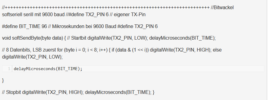
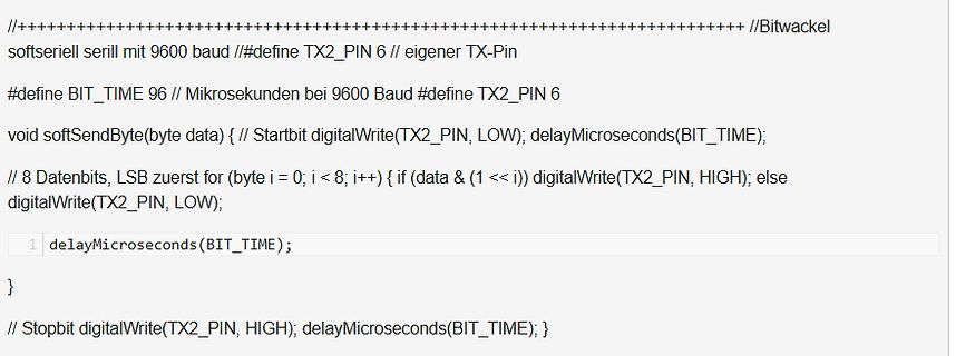
bei 9600 Baud #define TX2_PIN 6 void softSendByte(byte data) { // Startbit digitalWrite(TX2_PIN, LOW); delayMicroseconds(BIT_TIME); // 8 Datenbits, LSB zuerst for (byte i = 0; i < 8; i++) { if (data & (1 << i)) digitalWrite(TX2_PIN, HIGH); else digitalWrite(TX2_PIN, LOW); 1 delayMicroseconds(BIT_TIME); } // Stopbit digitalWrite(TX2_PIN, HIGH); delayMicroseconds(BIT_TIME); }
-
Thread
SWD-Zugriff funktioniert nur über ProgrammerSocket
Werden die Pegel von einem anderen Baustein heruntergezogen? NRST messen. Bleibt NRST dauerhaft High? Kann der ST-Link den Pin wirklich auf Low ziehen? Versorgung messen. Liegen während des Verbindungsversuchs stabile 3,0–3,3 V am STM32 an? Schaltplan oder Fotos der Platine ansehen. Oft erkennt
einen Reset auslösen? Es könnte ja eventuell eine andere Resetquelle geben die den Reset-Pin auf "High" hält.
-
Thread
Pollin insolvent, Arduino mit Zephyr, quadratische Displays uvam
verspricht Seeed folgendes: [c] A highly integrated, card-sized form factor optimized around a high-capacity 1100mAh battery, delivering up to 5 days of runtime while remaining compact and portable for outdoor carry and off-grid communication. [/c] ### Starterkit für NoteCard Skylo verfügbar
, image processing, and scientific computing, and is combined with fast, multi-channel memory and high-speed connections (PCIe and AXI, the same kind of high-bandwidth links used to connect components inside servers and data centers). [/c] ### RISC/V zur Zweiten – DGEMM in Optimiert Der Kampf
-
Thread
Copilot für Microcontroller verwenden
devdesc", auch OpenSource). Deckt auch > heute noch die meisten Beduerfnisse ab. Auch ziemlich High-Level, damit kann ich keinen Accelerometer-IC ansteuern.
devdesc", auch OpenSource). Deckt auch >> heute noch die meisten Beduerfnisse ab. > > Auch ziemlich High-Level, damit kann ich keinen Accelerometer-IC > ansteuern. Der devdesc XML-Dialekt ist wie SVD, kann nur eim bisschen mehr. Mehr als die Low-Level-Registermap und die generierten Header braucht
-
Artikel
FPGA
50MHz x 16 Bit für die Daten. Ab diesem Punkt ist dann wieder ein schneller softcore einsetzbar. High-Speed-USB. Für die Übersetzung auf den immer schnelleren USB-Bus (inzwischen bis 5Gb Bandbreite!) stehen Chips zur Verfügung, die sich in vergleichsweise einfacher Weise ansteuern lassen. Eine passende
Boards - Zusammenstellung günstiger FPGA Boards unter 100$ Ein Vortrag, auf Englisch: General Purpose, Low Power Supercomputing Using Reconfiguration Logic - FPGA-Projekte, Opensource, jeder kann seine Eigenen einstellen und an anderen mitarbeiten. U.a. gibt es verschiedene CPUs für FPGAs. Projekt "FDIL
-
Thread
Dual Triac Schaltung mit Verriegelung?
Erfahrung und wollte mal hören, wie ihr meine Schaltung bewertet. Auf der LED Seite würde 2 mal high oder 2 mal low Pegel keine LED zum leuchten bringen, nur wenn ein Ausgang low und der andere auf high steht würde eine LED leuchten. Triac soll ein 800V Snubberless Typ mit 5 oder 10 mA Gatestrom
Thomas schrieb im Beitrag #8080621: > Auf der LED Seite würde 2 mal high oder 2 mal low Pegel keine LED zum > leuchten bringen, nur wenn ein Ausgang low und der andere auf high steht > würde eine LED leuchten. Das ist leider nur die halbe Miete. Eine harte Umschaltung
-
Thread
FDA in single-ended output Konfiguration verwendbar?
Idee, den ADL5511 zu verwenden). Die Idee wäre, das Wandeln und Kopieren mit einem schnellen, low-noise, high slew-rate FDA zu machen. Für die Amplitudenerfassung ist die Phase ja egal :). In der Simulation habe ich bisher die ADA4927, ADA4932 und ADA4938 ausprobiert. Ich weiß, dass die FDA
-
Thread
AD DC Konverter am Nabendynamo
am Akku nicht größer als 3,7 Volt werden kann. Gegen Tiefentladung hilft die hoffentlich vorhandene Low-Batt-Anzeige an dem Bluetoothgerät. Michael B. schrieb im Beitrag #8080254: > Warum nutzt die Schaltung nicht was seit 1980 erfunden wurde? Was wurde denn 1980 erfunden?
Da wäre das Datenblatt: https://datasheet.octopart.com/HT7333A-Holtek-datasheet-94578991.pdf "High input voltage (up to 12V)" Wenn da anstelle der vorhanden Batterien eine CR2477 hineinpasst, Abmessungen: 24 × 7,7 mm, gibt es mehrere Möglichkeiten, was da hineingesteckt werden kann. Z.B. davon
-
Thread
ESP32-S31 in Massenproduktion, MERICRON als ESP32-Alternative uvam
and is now available for purchase. Designed for next-generation AIoT applications, ESP32-S31 is a high-performance dual-core RISC-V SoC with comprehensive wireless connectivity, making it ideal for smart home hubs, smart speakers, edge AI devices, industrial automation, and more. [/c] Als „offiziellen
storage.unsafe_disable_usb_drive(), to disable the USB CIRCUITPY drive after the host has mounted it. • Lower the default WiFi power from 20 dBm to 15 dBm on all boards with chip antennas. • USB host fixes. • Espressif BLE fixes. • ESP-NOW works again on Espressif. • Update TinyUSB. [/c] Zu beachten
-
Thread
Adressdekoder für 68k CPU
Gekürzter Auszug [code] input cpu_rd, //cpu read input cpu_hwr, //cpu high write input cpu_lwr, //cpu low write input ovl, //overlay kickstart rom over chipram input boot, //overlay bootrom over chipram ... //chipram, kickstart
-
Thread
Bosch CJ125 mit AVR AT90CAN64
wir beim Schaltplan weitermachen? TX_CAN und RX_CAN haben beide die gleiche Signalrichtung. CAN_HIGH und CAN_LOW sollte bidirektional sein. Spannungsversorgung ist kein Label sondern ein Symbol ... -> https://www.mikrocontroller.net/articles/Schaltplan_richtig_zeichnen Rene S. schrieb im Beitrag
und habe mir mal dein Logfile angeschaut. Was gleich auffällt ist das CJ125 DIAG: 0x2855 Heißt: Low Battery. Du solltest dir das Fehlerregister periodisch ausgeben lassen, das gibt wertvoll Hinweise.
-
 Bild
Bild
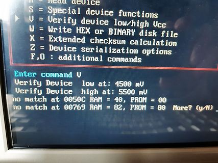
Textmenü eines Programms zur Geräteprüfung
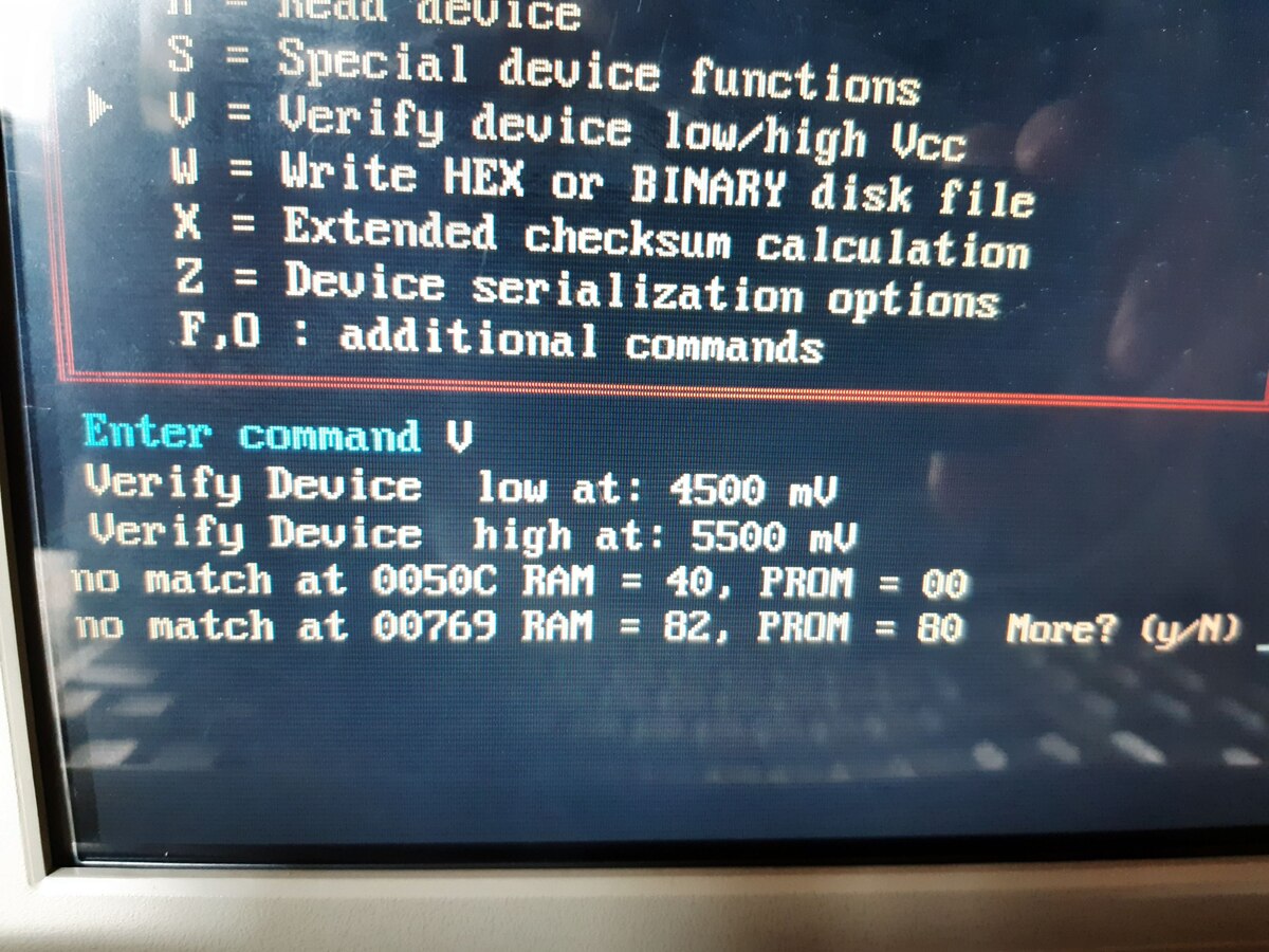
S = Special device functions V = Verify device low/high Vcc W = Write HEX or BINARY disk file X = Extended checksum calculation Z = Device serialization options F,O : additional commands Enter command V Verify Device low at: 4500 mV Verify Device high
-
Thread
Keine änderung des BLE Namens des esp32c3
received; //wird in loop bearbeitet if (received == "ON") { digitalWrite(LED_PIN, HIGH); } else if (received== "OFF") { digitalWrite(LED_PIN, LOW); } Serial.print("Empfangen: "); Serial.println(received); String reply = "Echo: " + received
pAdvertising->start(); }//setup void aktion(int nr) { if( nr==1) { digitalWrite(LED_PIN, LOW); delay(500); digitalWrite(LED_PIN, HIGH); delay(500); digitalWrite(LED_PIN, LOW); delay(500); digitalWrite(LED_PIN, HIGH); } } void Auswertung_Test
-
Thread
ESP8266 D1 Mini + Relaismodul: Relais bleibt bei D1 dauerhaft eingeschaltet
Das grundlegende Problem ist ja folgendes: Ich sage in meinem Programm grundlegend D1 soll LOW oder HIGH. Also irgendwas mit D1. Wenn ich dann das Relais in D1 stecke, schaltet es sofort. Egal ob im Programm LOW oder HIGH steht. Wenn ich das Relais anstelle von D1 in D2 stecke, am Programm
. Ich hatte die High-aktive Variante im Sinn, war dann aber so dumm, denn Schaltplan der Low-aktiven zu zeigen.
-
Thread
PCB Komponentenidentifikation
Beitrag #8077236: > 1.) Der HD2AD100T --> Müsste wohl irgend ein Gate Treiber sein, oder? > Sind ein High Side und ein Low Side Mosfet in der nähe https://www.onsemi.com/download/data-sheet/pdf/fan3100t-d.pdf
. schrieb: >> 1.) Der HD2AD100T --> Müsste wohl irgend ein Gate Treiber sein, oder? >> Sind ein High Side und ein Low Side Mosfet in der nähe > > https://www.onsemi.com/download/data-sheet/pdf/fan3100t-d.pdf Treffer!
-
Thread
Elko verträgt falsch gepolt wieviel Spannung / DC Blocker
Ich würde sowas nehmen: https://www.reichelt.de/de/de/shop/produkt/elko_radial_4_7_mf_10_v_105_c_low_esr-200093 4 Stück, zwei parallel um auf höhere Strombelastbarkeit zu kommen (2 x 3,75 A = 7,5 A) und weniger Innenwiderstand 12 mOhm : 2 = 6 mOhm zu kommen - und dann das gleiche noch mal seriell
voltage first. Note the AC voltage range, then manually select a DC voltage range equal to or higher than the AC range. This procedure improves the accuracy of the DC measurement by ensuring that the input protection circuits are not activated.
-
 Bild
Bild
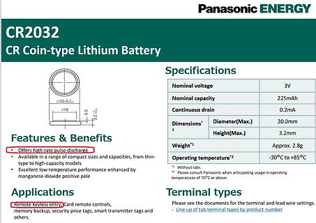
Datenblatt einer Panasonic CR2032 Lithium-Knopfzelle
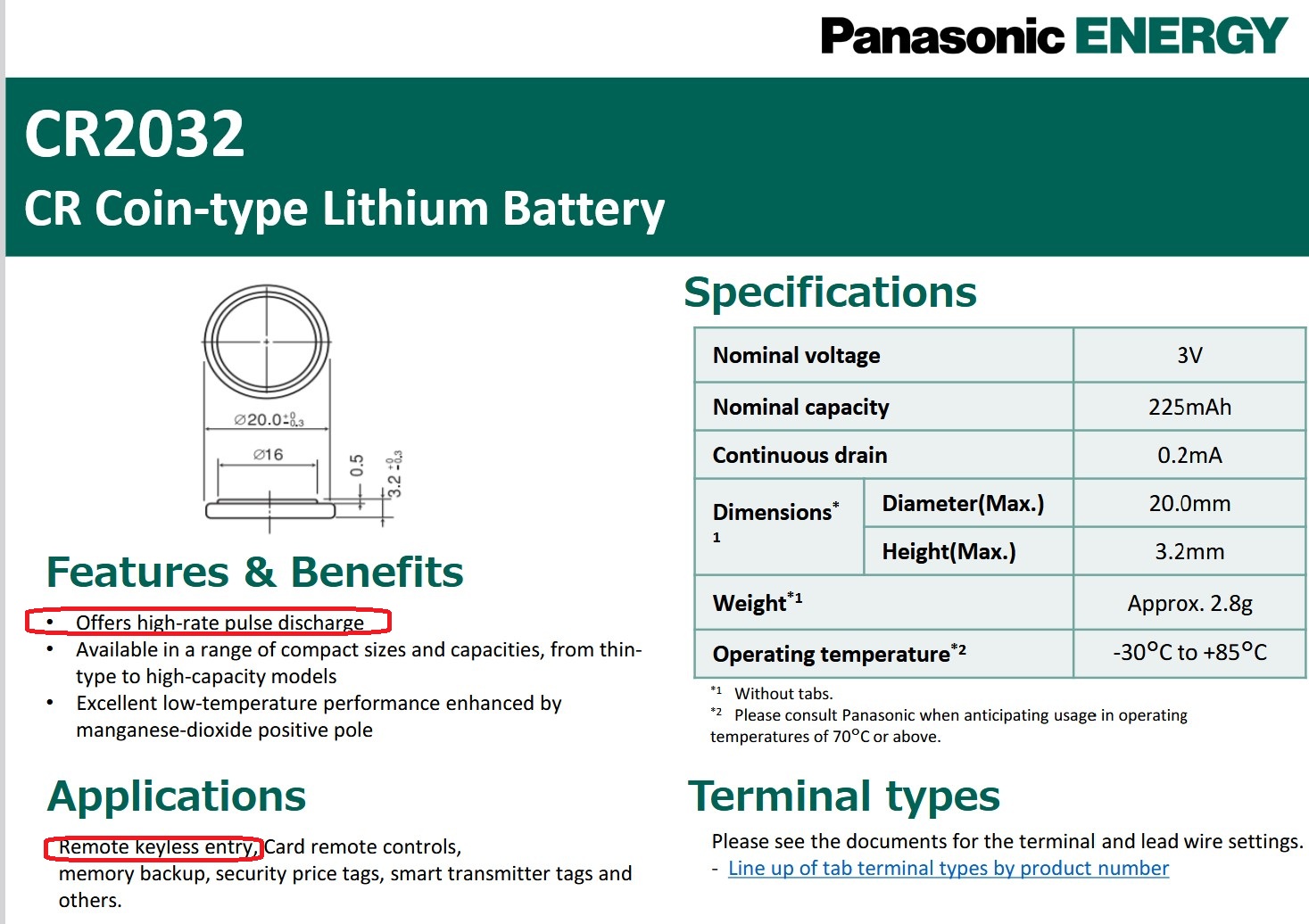
Max.) 3.2mm Weight*1 Approx. 2.8g Operating temperature*2 -30°C to +85°C Features & Benefits Offers high-rate pulse discharge Available in a range of compact sizes and capacities, from thin-type to high-capacity models Excellent low-temperature performance enhanced by manganese-dioxide positive pole Applications
-
Thread
Ein Fototransistor - nur welcher?
mode pinMode(pinReceiver, INPUT); // set the laser pin to output mode digitalWrite(pinLaser, HIGH); // emit red laser Serial.begin(9600); // Setup serial connection for print out to console } void loop() { int value = digitalRead(pinReceiver); // receiver/detector send either LOW or HIGH
-
Thread
Quelloffene Spracherkennung, LoRA am Raspberry Pi, neue Jetson-Module uvam
tracking, and overall preference. In terms of hit score, the gamers’ win rate improved by 38% at the highest level of 480Hz compared to the lowest level of 60Hz. Despite significant gains being achieved even at 240Hz, the win rate increased by an additional 10% at 480Hz. This indicates that gaming performance
-
 Bild
Bild
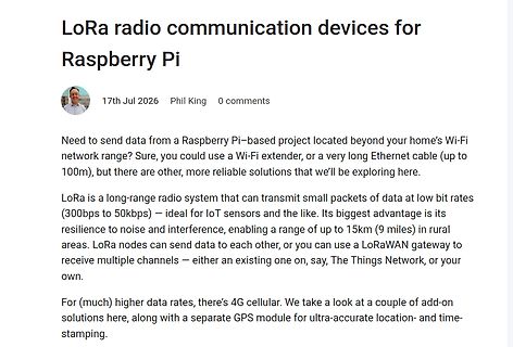
Artikel über LoRa Funkmodule für Raspberry Pi
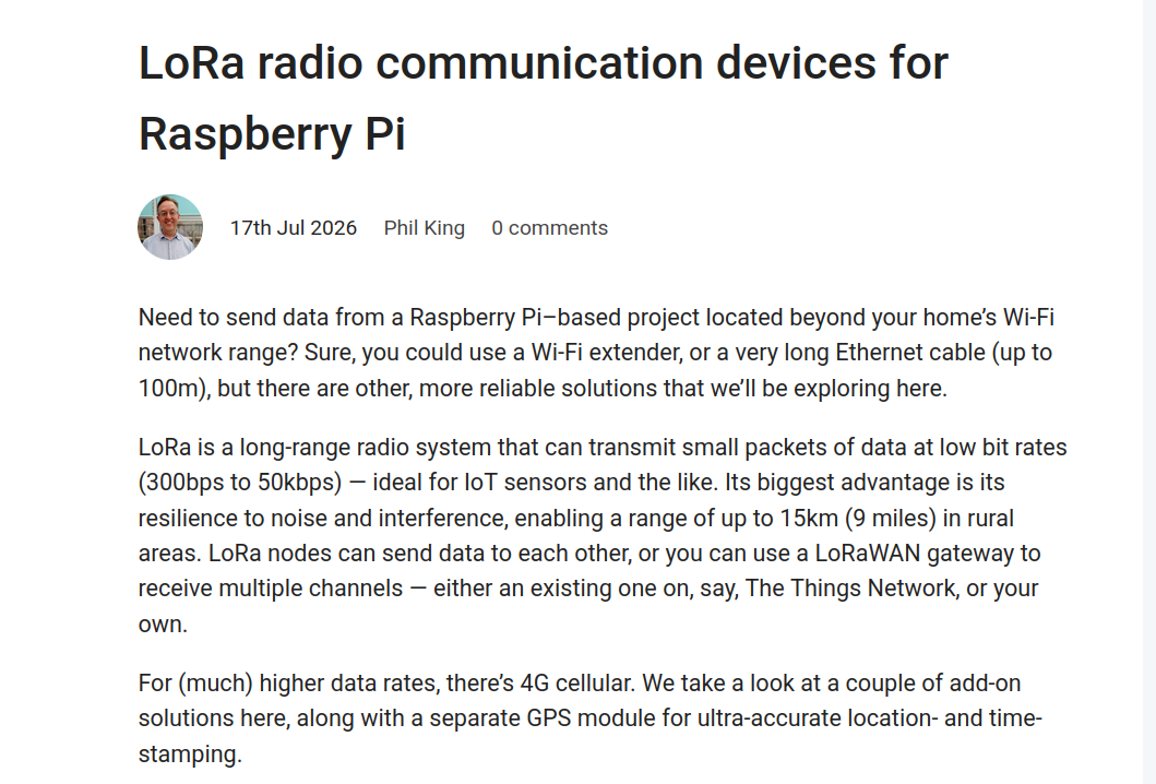
we'll be exploring here. LoRa is a long-range radio system that can transmit small packets of data at low bit rates (300bps to 50kbps) - ideal for IoT sensors and the like. Its biggest advantage is its resilience to noise and interference, enabling a range of up to 15km (9 miles) in rural areas. LoRa nodes
-
Thread
Erstaunlich kritischer Beitrag zum Starship von SpaceX Gesperrt
würden dein Verhalten als psychiologische Manipulation bezeichnen, neudeutsch gaslighting. > Der Löwe123 Bin auch Sternzeichen Löwe ;-) KI-Antwort "Das Sternzeichen Löwe (23. Juli bis 23. August) ist ein feuriges, selbstbewusstes und großzügiges Zeichen. Zu den wichtigsten Stärken zählen sein
deinen Frieden mit Herrn Musk finden kannst. Hass kann niemals die Antwort sein. Grüße Der Löwe123
-
Thread
Reverse Engineering PCB Gesperrt
V-DC-Motor soll über einen Taster ein- und ausgeschaltet werden. Ideal wäre eine Zweistufenregelung (Low und High). Eine Drehrichtungsumkehr ist zwingend erforderlich, damit das Gerät auch problemlos von Linkshändern genutzt werden kann. Zusätzlich ist eine Beleuchtung notwendig, die die Handhabung deutlich
-
Thread
Hilfe beim KiCad-Layout gesucht: 2-Fach Motorsteuerung (KFZ-Bereich)
hoffe auf einen Hinweis. Schaltung DRV8874PWPRQ1 PH/EN-Modus (PMODE = GND) VM = 12 V nSLEEP = HIGH EN = HIGH PH = HIGH bzw. LOW (je nach Drehrichtung) VREF ≈ 2,6 V CPH/CPL = 22 nF VCP/VM = 100 nF Exposed Pad mit GND verbunden Gemessene Werte Bei aktivierter Motoransteuerung: VM = ca. 12,1 V EN = 3,2 V PH = 3,2 V nSLEEP = 3,2 V nFAULT = HIGH (kein Fehler) OUT1 ≈ 0,6–0,7 V OUT2 ≈ 0,6–0,7 V VCP liegt nicht über VM (teilweise sogar unter VM) Dadurch schaltet die H-Brücke überhaupt nicht durch und der Motor erhält keine Spannung. Bereits
-
 Bild
Bild
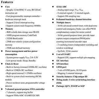
Technische Spezifikationen eines Mikrocontrollers
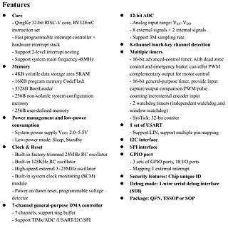
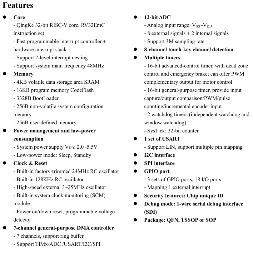
BootLoader - 256B non-volatile system configuration memory - 256B user-defined memory Power management and low-power consumption - System power supply VDD: 2.0~5.5V - Low-power mode: Sleep, Standby Clock & Reset - Built-in factory-trimmed 24MHz RC oscillator - Built-in 128KHz RC oscillator - High-speed external
-
 Bild
Bild
Technische Spezifikationen eines Mikrocontrollers
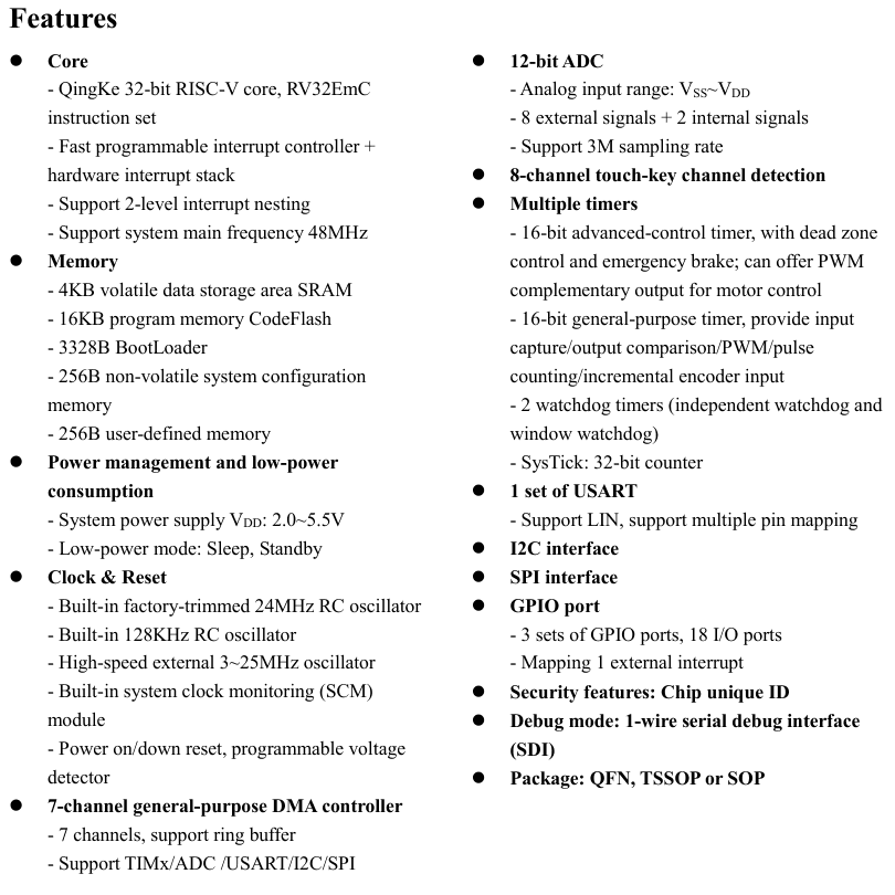
BootLoader - 256B non-volatile system configuration memory - 256B user-defined memory Power management and low-power consumption - System power supply VDD: 2.0~5.5V - Low-power mode: Sleep, Standby Clock & Reset - Built-in factory-trimmed 24MHz RC oscillator - Built-in 128KHz RC oscillator - High-speed external