-
PDF
8x8.pdf
1.22 inch ( 31.0mm ) 8X8 DOT MATRIX SINGLE COLOR LED DISPLAY LED DISPLAY DATA SHEET P/N:M122880EWB M123880EWB PREPARED BY:SAM LU APPROVED BY:JACK WU DATA:NOV,21,2000 REV.:0 ACCEDE OPTOELECTRONICS CO.,LTD 1.22 inch ( 31.0mm ) 8X8 DOT MATRIX SINGLE COLOR LED DISPLAY DESCRIPTION The 1.22 inch (31.0mm) height 8X8 dot matrix led display. This device utilizes red orange LED chip. The device has black face and white segments. The red orange
-
PDF
ht16K33v110_Datenblatt.pdf
a 13*3 (MAX.) matrix key scan circuit. The software configuration features of the HT16K33 makes it suitable for multiple LED applications including LED modules and display subsystems. The HT16K33 is compatible with most
in „HT16K33 - habe ein Problem damit“ · Mikrocontroller und Digitale Elektronik ·
-
Datei
max7221__5x7_dot_matrix_.h
//////////////////////////////// //// MAX7221.H //// //// Driver for Serially Interfaced, 8-Digit, LED Display //// //// //// //// max7221_init() Must be called before any other function. //// //// //// //// max7221_put(addr,data) Send data to LED-matrix //// //// //// //// max7221_clear() Blank LED-display
in „Max7221 text routieren“ · Mikrocontroller und Digitale Elektronik ·
-
 Bild
Bild
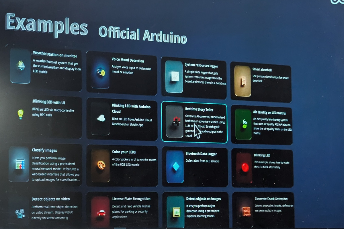
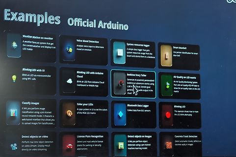
Abfotografierter Bildschirm mit Arduino Projektbeispielen
adventure stories using LLM in Cloud. Stretch goal: generate audio output in the cloud Air Quality on LED matrix An Air Quality Monitoring System that uses air quality AQI API data to show the air quality state on the LED matrix Classify Images It lets you perform image classification using a pre-trained
in „Arduino Q, Qualcomm kauft Arduino, neue IDE ante Portas“ · Mikrocontroller und Digitale Elektronik · · Fotos
-
 Bild
Bild
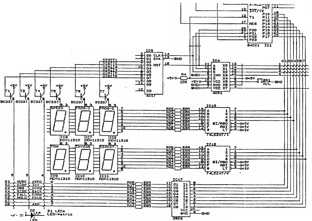
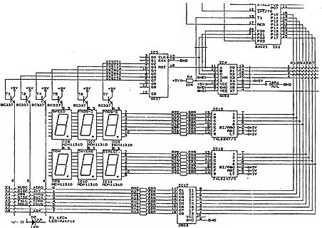
Schaltplan mit Mikrocontroller, 4017, 74LS247 und 7-Segment-Anzeigen
HDN1310, IC9 HDN1310, IC10 HDN1310, IC11 HDN1310, IC15 74LS247/2, IC17 2803, BC337, R4 10K, D2 21 LEDs LED-matrix
in „7-Segent / LED- und Tastenmatrix Schaltungslösung“ · Mikrocontroller und Digitale Elektronik · · Schaltpläne
-
Datei
UCF_File.txt
INST "bank1_diff_ch_matrix<4><1>" TNM = din1_timegroup; INST "bank1_diff_ch_matrix<5><1>" TNM = din1_timegroup; INST "bank1_diff_ch_matrix<6><1>" TNM = din1_timegroup; INST "bank1_diff_ch_matrix<7><1>" TNM = din1_timegroup;
-
PDF
IOWarrior_56_Datasheet.pdf
LCD function is enabled, it does go high when IO- Warrior enters suspend mode or when the LCD 4.2.4 LED Matrix Mode Pins function is disabled. IO-Warrior56 supports driving a LED matrix with up to 8x64 LEDs. By default the follwing pins should be used for Function IOW56 controlling the CS lines of graphic
in „Wie groß ist Uce in einem IC?“ · Analoge Elektronik und Schaltungstechnik ·
-
PDF
IOWarrior_56_Datasheet.pdf
LCD function is enabled, it does go high when IO- Warrior enters suspend mode or when the LCD 4.2.4 LED Matrix Mode Pins function is disabled. IO-Warrior56 supports driving a LED matrix with up to 8x64 LEDs. By default the follwing pins should be used for Function IOW56 controlling the CS lines of graphic
in „Wie groß ist der standard verwendete Ausgangsstrom Strom?“ · Mikrocontroller und Digitale Elektronik ·
-
Datei
main.c
SystemCoreClockUpdate(); /* Initialise the GPIO block */ gpioInit(); /* set direction to input */ //gpioSetDir(0,LED_GREEN,0); set_led(LED_GREEN); /* Configure the multi-rate timer for 1ms ticks */ mrtInit(SystemCoreClock/1000); /* Configure the switch matrix (setup pins for SCT and GPIO) */ SwitchMatrix_Init(); /
in „LPC810 SCT-PWM Projekt Fehler“ · Mikrocontroller und Digitale Elektronik ·
-
Datei
Matrix_Abfrage.txt
/* FLASH.C - LED Flasher for Phytecs Rapid Development Kits */ #include <reg517.h> /* include 80517 header file */ //#include <stdio.h> /* Standard I/O functions */ //#include "serinit.h" /* Automatic baudrate detection */ // Port4.0 = Spalte 1 // Port4.1 = Spalte 2 // Port4.2 = Spalte 3 // Port4.3 = Zeile 1 // Port4.4 = Zeile 2 // Port4.5 = Zeile 3 // Port4.6 = Zeile 4 //mainprogram sbit Spalte1 = P4^0; sbit Spalte2 = P4^1; sbit Spalte3 = P4^2; sbit Zeile1 = P4^3; sbit Zeile2 = P4^4; sbit Zeile3 = P4^5; sbit Zeile4 = P4^6; void wait (void) { /* wait function */ ; /* only to delay for LED flashes
in „3x4 Matrixtastatur-Ansteuerung mit MiniModul 537“ · Mikrocontroller und Digitale Elektronik ·
-
Datei
RGB.c
----------------------------------------------------------| | Programm zur Ansteuerung einer RGB - LED Matrix 8x8 | | mittels Schieberegisterausgängen | | | | | | Erweiterung für Ausgabe einer Dual 14 Segment LED Anzeige | | | | | | Autor: Arne Pfäffle | | V 1.0 | | 18.09.2013 | | | | Ausgabe mittels
in „RGB - LED Matrix mit Schieberegistern“ · Mikrocontroller und Digitale Elektronik ·
-
PDF
FEPST3.mdi.pdf
Development Kits MODEL: FEPST3 FEPST3 KEY FEATURES 1) POWER SUPPLY UNIT. 2) MICROCONTROLLER UNIT. 3) 4X4 MATRIX KEYPAD UNIT. 4) FOUR LEDs DISPLAY UNIT. 5) TWO MULTIPLEXED 7SEG DISPLAY UNIT. 6) 2X16 LCD DISPLAY UNIT. 7) ICSP AND SERIAL UNIT. POWER SUPPLY UNIT The power may be supplied from 1- Any DC walwart power
in „Atmel Entwicklungsboard LCD, 4X4 Matrix Keypad, USB“ · Markt ·
-
Datei
LED-Stripe_90CAN128.asm
=============== ; ; Hier ist der zyklische Interrupt, der im ersten Teil ; den Datenstrom für die LEDs erzeugt und im zweiten Teil ; die GRB-Matrix der LEDs updated. ; ;======================================================== Timer1_Irq: ;- Teil 1: Bitstrom ausgeben ----------------------- Txd_WS2811
in „WS2812 Ansteuerung in AVR-Assembler (ohne SPI o.ä., beliebige Pins verwendbar)“ · Projekte & Code ·
-
PDF
DV-20400.pdf
SPECIFICATIONSFORLIQUIDCRYSTALDISPLAYMODULE MODELNO:DV-20400-S1FBLY/R22 1. SCOPE The DV-20400-S1FBLY/R22, dot-matrix LCD unit of a 5 x 7- dot 20-character 4-line dot-matrix LCD panel, LCD driver, controller LSI and yellow green back-light LED fabricated on a single PCB. Incorporating mask ROM-based character generator
in „LCD_4Bit_PIC_Init“ · Mikrocontroller und Digitale Elektronik ·
-
Datei
myCode.txt
an beide MAX7219 senden sendByte( MAX7219_MODE_DECODE, 0x00,MAX7219_MODE_DECODE, 0x00);// using an led matrix (not digits) //Scanlimit an beide MAX7219 senden sendByte(MAX7219_MODE_SCAN_LIMIT,0x07 , MAX7219_MODE_SCAN_LIMIT, 0x07);// show all 8 digits //Intensity an beide MAX7219 senden sendByte( MAX7219
in „HD44780 emulieren“ · Mikrocontroller und Digitale Elektronik ·
-
Datei
display.c
>= cnt) { led.matrix[y + cnt][x - cnt] |= NEW_STATE; } } else { if (y + cnt < WC_ROWS && x + cnt < WC_COLUMNS) { led.matrix[y + cnt][x + cnt] |= NEW_STATE; } } } } if (led.state[yi + x] & CALC_STATE) { led.state[
-
Datei
LEDmatrix.h
#include "mystdtypes.h" #ifndef _LED_MATRIX_H_ #define _LED_MATRIX_H_ #ifdef __cplusplus extern "C" { #endif #define LED_MAT_COL_PORT1 PORTC #define LED_MAT_COL_PORT2 PORTD #define LED_MAT_ROW_SHIFT_PORT PORTA #define LED_MAT_ROW_SHIFT_RESET
in „Game of Life in C für µC“ · Mikrocontroller und Digitale Elektronik ·
-
Datei
Codeschloss.c
Anschluss für Sirene #define Schocker P6.5 //Anschluss für Elektroschocker an der Türklinke #define Led_Scharf P6.6 //Signalisiert, dass die Alarmanlage scharf ist #define Led_Merker P6.7 //Signalisiert, dass die Alarmanlage mindestens eimal ausgelöst hat void lcdinit(void); //Funktion zur Initialisiung der LCD void Auswertung(void); //Auswertung der Taste unsigned char MatrixLesen(void); //Funktion zum Lesen der Matrix void Wait(unsigned int); //Zeitschleife void ZahlAufnahme(void); //Auswertung der Taste void intinit(void); //Interrupt Initialisierung void CodeAbgleich
in „Codeschloss mit 8051“ · Mikrocontroller und Digitale Elektronik ·
-
PDF
datenblatt2.pdf
www.datamodul.com Preliminary Specification for LCD Module Type Item No.: MGLS12864D-01 MGLS12864D-LED03-LV2 1. General Description • 128 x 64 dot matrix STN LV2 positive green-yellow transflective dot matrix LCD graphic module. • Driving scheme: 1/64 multiplexed drive, 1/9 bias. • Viewing direction
in „LCD 128x64 Initialisieren“ · Mikrocontroller und Digitale Elektronik ·
-
PDF
A500_EA0FP481-43SW-DB.pdf
Doppeltastendrücke erkennen zu können. Es stehen weiterhin 4 Eingänge und 4 Ausgänge zur Verfügung. 2x2 Matrix 1x4 Matrix 4x0 Matrix 4x4 Matrix Technische Änderung vorbehalten. EAeDIPTFT43-A Wir übernehmen keine Haftung für DruckfehlerundApplikationsbeispiele. Seite 10 DATENÜBERTRAGUNGSPROTOKOLL (SMALL PROTOKOLL
in „eDIPTFT43 Ansteuerungsarten“ · Mikrocontroller und Digitale Elektronik ·
-
 Bild
Bild
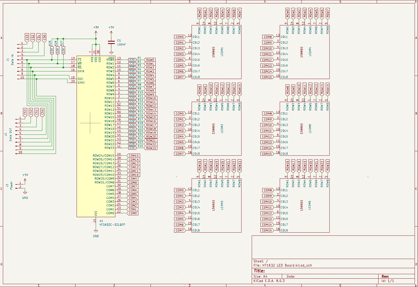
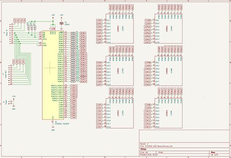
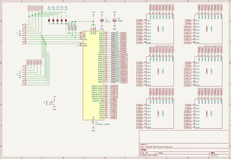
Schaltplan eines LED-Treibers mit HT1632C
DATA IN, CS1, CS2, CS3, CS0, +5V, C1 100nf, VDD, VSS, GND, PC, PB, SYNC, ROW1 bis ROW32, COL1 bis COL18, LED1 bis LED5, HT1632C-52LQFP, KiCad E.A.D.A. 8.0.3
in „HT1632C mit LED Punkt Matrix“ · Mikrocontroller und Digitale Elektronik · · Schaltpläne
-
 Bild
Bild
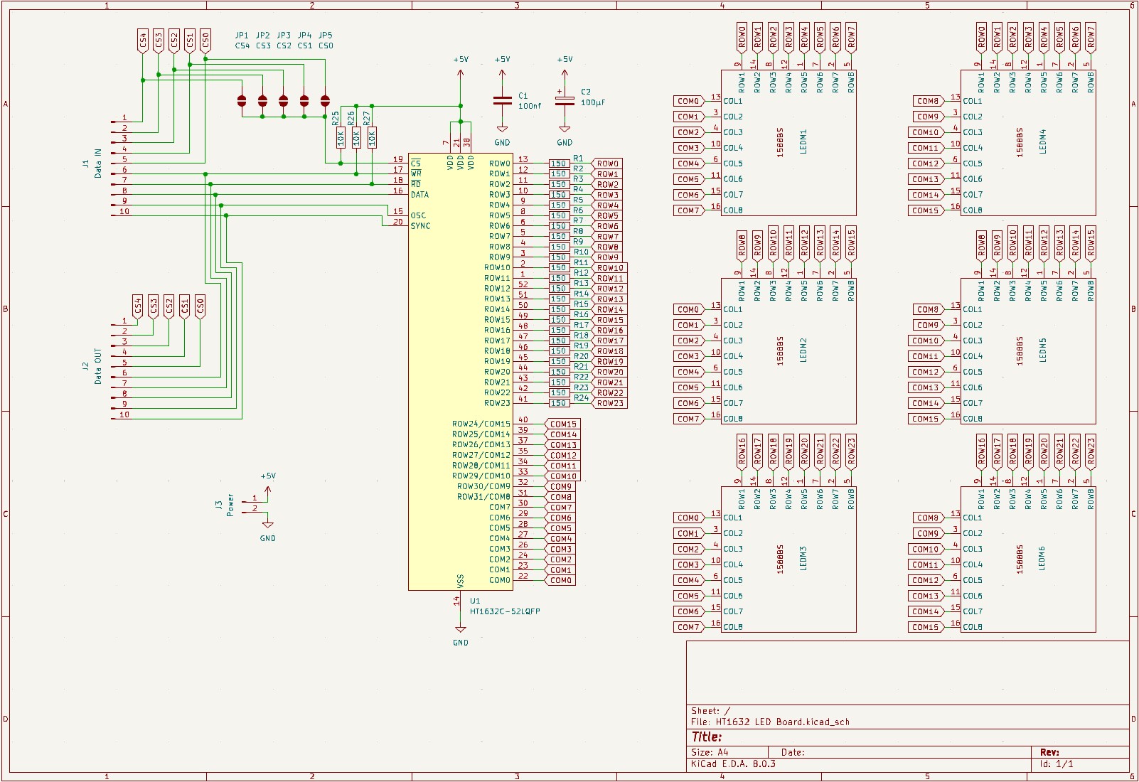
Schaltplan eines HT1632C LED-Treibers
J1 JP1 JP2 JP3 JP4 JP5 CS1 CS2 CS3 CS4 +5V C1 100nf C2 10nf GND U1 HT1632C-52LQFP ROW1 bis ROW32 COM1 bis COM16 LED1 bis LED16 KiCad_sch, File: HT1632 LED board.kicad_sch
in „HT1632C mit LED Punkt Matrix“ · Mikrocontroller und Digitale Elektronik · · Schaltpläne
-
PDF
TARGET__LED-Matrix.T3000.pdf
3 4 6 7 8 9 0 1 2 3 4 5 7 8 9 0 1 2 2 2 2 2 2 2 2 2 2 2 2 2 2 2 2 2 2 2 2 2 D D D D D D D D D D D D D D D D D D D D 8 8 R 1 R 1 IC8 F C R83 T44 R82 T45 N PB5 Vcc 1 PB3 PB2 PB4 PB1 5,76K BC337-40 5,76K BC337-40 GND PB0 ATTINY13(DIL8) R37 IC1 2,15K IN OUT J A 1 A 8 - T LM1084IT-5.0 6 7 0 2 3 4 5 6 7 8 9 0 1 3 4 5 6 7 8 9 0 1 2 4 5 6 7 K C D D D D D D D D D D D D D D D D D D D D D D D D D D D D D D D D D D D D D P R38 B LP1 2,15K 2 + 0 T 7 LP2 3 3 3 3 4 4 4 4 4 4 4 4 4 4 5 5 5 5 5 5 5 5 5 5 6 6 6 6 6 6 6 6 6 6 7 7 7 B D D D D D D D D D D D D D D D D D D D D D D D D D D D D D D D D D D D D R39 - 2,15K
in „Problem mit Schieberegister“ · Mikrocontroller und Digitale Elektronik ·
-
PDF
regia512-google-de.pdf
in die Matrix eingegebene Programm. Wenn sie im Moment schon aktiv wäre, würde sie einfach weiterarbeiten. Die Nummer der ausgewählten Matrix wird im Feld # MATRIX # angezeigt. Um die Matrix zu blockieren, drücken
in „Sport frei - Lichtmixer SGM Regia 512 S 36 DMX wiederbeleben“ · Analoge Elektronik und Schaltungstechnik ·
-
PDF
DB_EA_ediptft32-a.pdf
stehen weiterhin 4 Eingänge und 4 Ausgänge zur Verfügung. 2x2 Matrix 1x4 Matrix 4x0 Matrix 4x4 Matrix Technische Änderung vorbehalten. Seite 9 Wir übernehmen keine Haftung für Druckfehler und Applikationsbeispiele. EA eDIPTFT32-A DATENÜBERTRAGUNGSPROTOKOLL (SMALL PROTOKOLL
in „Ausgabe eines Wertes beim EA TFT 32 Display“ · Mikrocontroller und Digitale Elektronik ·
-
PDF
85272_LED_Cube_LC444.pdf
6 BELEUCHTUNG LichteffektinderdrittenDimension– 4x4x4-LED-CubeLC444 Ein 3D-Lichteffekt der Extraklasse – 64 LEDs sind dreidimensional in einem Würfel so angeordnet, dass sie einzeln und in der Helligkeit steuerbar sind. Die Ansteuerungsmuster sind sehr einfach
in „Ansteuerungsfrage LED Cube von ELV“ · Mikrocontroller und Digitale Elektronik ·
-
Datei
Code.txt
listed. https://xantorohara.github.io/led-matrix-editor you can also easily turn the icons 90 or 180 degrees on this website if the matrix does not show the right orientation. Also please contact me if you something isn't working properly so it can be fixed in the next update. Have fun! */ #include <MaxMatrix.h> /* If you would like to use a hall effect sensor (magnet sensor) to turn off the LED-matrices when the visor is taken off, you can uncomment the line below by deleting the 2 slashes. */ //#define
in „Max7219 an Arduino Nano will nicht“ · Mikrocontroller und Digitale Elektronik ·
-
Datei
Protogen_OS_V3.1_mod__1_.ino
listed. https://xantorohara.github.io/led-matrix-editor you can also easily turn the icons 90 or 180 degrees on this website if the matrix does not show the right orientation. Also please contact me if you something isn't working properly so it can be fixed in the next update. Have fun! */ #include <MaxMatrix.h> /* If you would like to use a hall effect sensor (magnet sensor) to turn off the LED-matrices when the visor is taken off, you can uncomment the line below by deleting the 2 slashes. */ //#define
in „Max7219 an Arduino Nano will nicht“ · Mikrocontroller und Digitale Elektronik ·
-
PDF
Datenblatt_E_DIP_TFT_32-A.pdf
Doppeltastendrücke erkennen zu können. Es stehen weiterhin 4 Eingänge und 4 Ausgänge zur Verfügung. 2x2 Matrix 1x4 Matrix 4x0 Matrix 4x4 Matrix Technische Änderung vorbehalten. EAeDIPTFT32-A Wir übernehmen keine Haftung für Seite 10 DruckfehlerundApplikationsbeispiele. DATENÜBERTRAGUNGSPROTOKOLL (SMALL PROTOKOLL
in „Probleme mit übertragung“ · Mikrocontroller und Digitale Elektronik ·
-
PDF
Datenblatt_E_DIP_TFT_32-A.pdf
Doppeltastendrücke erkennen zu können. Es stehen weiterhin 4 Eingänge und 4 Ausgänge zur Verfügung. 2x2 Matrix 1x4 Matrix 4x0 Matrix 4x4 Matrix Technische Änderung vorbehalten. EAeDIPTFT32-A Wir übernehmen keine Haftung für Seite 10 DruckfehlerundApplikationsbeispiele. DATENÜBERTRAGUNGSPROTOKOLL (SMALL PROTOKOLL
in „Display am Attiny 841“ · Mikrocontroller und Digitale Elektronik ·
-
Datei
ws6812_test_zwo.c
bg_white) { for (uint8_t i = 0; i < ANZAHL_SPALTEN; i++) { for (uint8_t j = 0; j < ANZAHL_ZEILEN; j++) { led[pixel[j][i]].r = bg_red; led[pixel[j][i]].g = bg_green; led[pixel[j][i]].b = bg_blue; led[pixel[j][i]].w = bg_white; } } } /* erzeugt eine Linie in der übergebenen Ringfarbe, die vor der übergebenen
in „LED-Matrix mit light_ws2812-library; Ansteuerungsgeschwindigkeit“ · Mikrocontroller und Digitale Elektronik ·
-
Datei
tetris.c
= 1; // Update der Matrix matrix[4] = matrix[3]; matrix[3] = matrix[2]; matrix[2] = matrix[1]; matrix[1] = matrix[0]; matrix[0] = tmp; } } } void Init() { InitPorts(); InitTimer(); } void InitPorts() { DDRA= 0xFF; DDRB= 0x1F
in „ATMega16 LED Matrix“ · Mikrocontroller und Digitale Elektronik ·
-
Datei
main.c
> #define TIME0 1 #define TIME1 3 #define TIME2 15 #define LOOPTIME 7 #define WAITTIME 500 #define LED_COUNT 20 #define DDR_BYTE 0 #define PORT_BYTE 1 uint8_t l; // Achtung! Hoer andere Reihenfolge als bei Christmas-Lights! uint8_t matrix[LED_COUNT][2] = { // DDR_BYTE PORT_BYTE // ABCD ABCD { 0b00000011
in „mal wieder Charlieplexing“ · Mikrocontroller und Digitale Elektronik ·
-
 Bild
Bild
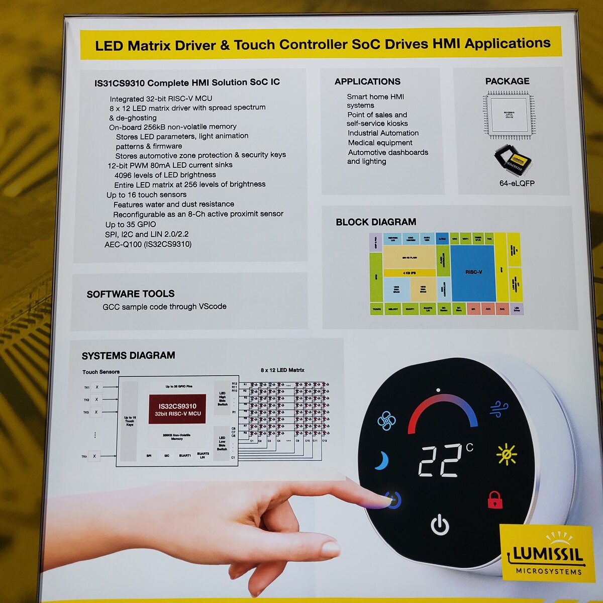
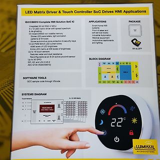
Datenblatt-Infografik für IS31CS9310 SoC
LED Matrix Driver & Touch Controller SoC Drives HMI Applications IS31CS9310 Complete HMI Solution SoC IC Applications: Smart home HMI systems, Point of sales and self-service kiosks, Industrial Automation
in „Electronica 2024, Tag 1 – Chips, AI-Chips, Altium Discover und Vergussmasse“ · Mikrocontroller und Digitale Elektronik · · Fotos
-
PDF
Project_Pegelmesser_Matrix_4Stellen.pdf
D ADP3339 B D T T T1 = ADP3339 I G O O I N U D G O O T U O PIN1 LED DOT MATRIX PIN8 PIN1 LED DOT MATRIX PIN8 u C4 C5 u R5 R3 R5 R3 1 1 PIN2 5x7 PIN9 PIN2 5x7 PIN9 = = R7 R1 R7 R1 C C PIN3 TA20-11 PIN10 PIN3 TA20-11 PIN10 C2 C4 C2 C4 PIN4 PIN11 PIN4 PIN11 GND 1 GND C3
in „LED Matrix (MAX6953) über I²C bus ansteuern“ · Mikrocontroller und Digitale Elektronik ·
-
PDF
VK16K33Datasheet.pdf
(16 segments and 8 commons) with a 13*3 (MAX.) matrix key scan circuit. The software configVK16K3makes it suitable for multiple LED applications including modules and display subVK16K33 is compatible with most microcontrollers and communicates via a two-line
in „VK16K33 vs HT16K33“ · Analoge Elektronik und Schaltungstechnik ·
-
PDF
BFE-Di_230_schematic.pdf
1 2 3 4 5 6 VCC J1 Amphenol 76384-310LF 1 Block LED Smart Matrix Logik Power 2 ~{INT} J1_~{INT} A 3 SDA A 4 SCL J1_SDA J1_SCL 5 6 A1 7 A2 J1_A1 J1_A2 8 9 10 File: block_led.kicad_sch File: smart matrix.kicad_sch File:Logic.kicad_sch File:power.kicad_sch
-
PDF
BFE-Di_230_schematic.pdf
1 2 3 4 5 6 VCC J1 Amphenol 76384-310LF 1 Block LED Smart Matrix Logik Power 2 ~{INT} J1_~{INT} A 3 SDA A 4 SCL J1_SDA J1_SCL 5 6 A1 7 A2 J1_A1 J1_A2 8 9 10 File: block_led.kicad_sch File: smart matrix.kicad_sch File:Logic.kicad_sch File:power.kicad_sch
-
Datei
Tastenfunke_tn24_1.asm
für Oszilloskop (Debug) ;Pin 7: PA6, ADC6 unbenutzt ;Pin 8: PA5, ADC5 unbenutzt ;Pin 9: PA4, ADC4 LED zur Anzeige von Tastendrücken gegen +5V ;Pin 10: PA3, ADC3 Matrix-Tastatur (5 Tasten) für Fahrkanal C ;Pin 11: PA2, ADC2 Matrix-Tastatur (5 Tasten) für Fahrkanal B ;Pin 12: PA1, ADC1 Matrix-Tastatur
in „Ladestatus eines Li-Ion-Akku messen“ · Mikrocontroller und Digitale Elektronik ·
-
PDF
LCD_DEM16216.pdf
F: B/W (FSTN) W: White D: B/W (DSTN) BACKLIGHT OPTION E: EL Panel OPERATING TEMPERATURE OPTION P: LED Lightguide Blank: 0 °C to +50 °C L: LED Lightbox H: -20 °C to +70 °C MODULES: ORDER LIST -: UNAVAILABLE TN: TWISTED NEMATIC DISPLAY VERSION /: AVAILABLE STN:SUPERTWISTED NEMATIC DISPLAY VERSION 0: STANDARD
in „lcd funkt leider nicht“ · Mikrocontroller und Digitale Elektronik ·
-
Datei
global.h
struct { uint8_t not_over_sound_limit:1; uint8_t screensaver:1; } volatile status_flags; uint16_t led_brightness_red[rows][columns]; //belichtungswert RGB der leds uint16_t led_brightness_green[rows][columns]; uint16_t led_brightness_blue[rows][columns]; uint8_t RandomL,RandomH; void init_matrix_data
in „7x7 RGB-LED matrix problem“ · Mikrocontroller und Digitale Elektronik ·
-
Datei
mendelmultimaterial.txt
float)’: Marlin.h:114: warning: only initialized variables can be placed into program memory area MatrixMath.cpp: In member function ‘void MatrixMath::MatrixCopy(float*, int, int, float*)’: MatrixMath.cpp:36: warning: unused variable ‘k’ MatrixMath.cpp: In member function ‘int MatrixMath::MatrixInvert
in „Seltsame Probleme bei Elektronik mit ATmega1284p nach Firmware-Update“ · Mikrocontroller und Digitale Elektronik ·
-
PDF
AS1106_07_Datasheet_v2_28.pdf
Package Thermal Resistance Θ JA) 24 Narrow DIP +75°C/W 24 Wide SOIC +85°C/W www.austriamicrosystems.com/LED-Driver-ICs/AS1106_07 Revision 2.28 15 - 21 AS1106, AS1107 Datasheet - Application Information 9.4 8x8 LED Dot Matrix Driver The application example in Figure 14 shows the AS1106 as an 8x8 LED dot matrix
in „Hilfe bei AS1106“ · Mikrocontroller und Digitale Elektronik ·
-
Datei
popong.c
#include "font.h" int pong_mode; /***************************************\ * Ports: * A0-6: Dot matrix rows * D0-4: Dot matrix columns * B0: Player 2 UP * B1: Player 2 DOWN * B2: Player 1 UP * B3: Player 1 DOWN * B4: Player 2 score LED * B5: Player 1 score LED \**************************************
in „AvR ATMega16 PoNG [Hängt sich neuerdings auf?!]“ · Mikrocontroller und Digitale Elektronik ·
-
Datei
FFT_Projekt.ino
FREQ_SAMPLE_AMOUNT); if(avg_freq){ lcd.setCursor(0, 0); lcd.print(avg_freq); lcd.setCursor(0, 1); LedMatrix(avg_freq); // lc.clearDisplay(0); }else lcd.print("zu leise!"); freq_sample_count = 0; } //LedMatrix(f); //LedMatrix1(); } double avg_frequency(double freq_arr[], unsigned short sample_count){
in „Arduino Frequenzerkennung scheitert an Einbindung einer DOT Matrix“ · Mikrocontroller und Digitale Elektronik ·
-
PDF
SeikoChar.pdf
26 AN No.SIG-CHMO9805A L2022 (20 x 2) 20 Characters x 2 line Mechnical Characteristics 5 x 8 Dot Matrix Item Specifications Unit Module size (H x V) 180 x 40 mm 1/16 Duty Thickness Reflective 10.5 mm 5V single Power Supply for LED 14.8 mm Wide Temperature type View ing area (H x V) 149.0 x 23.0 mm Character
in „Display Seiko L2432 und Kontrastproblem“ · Mikrocontroller und Digitale Elektronik ·
-
Datei
Slave.c
void output_ausschalten(void); uint8_t ausgabe (uint8_t temp, uint8_t feld); uint8_t berechnung_matrix(uint8_t anzahl_led); void anzeige(uint32_t anzahl_led, uint8_t rotgruen); void analogwandlung(void); uint32_t Mittelwert_bilden(void); void Differenz_bilden(void); uint32_t beschleunigung_berechnen
in „TWI - Wie lege ich die Adresse von einem Slave fest?“ · Mikrocontroller und Digitale Elektronik ·
-
PDF
DLR1414.PDF
for Hand Held Equipment • Built- in Memory DESCRIPTION The DLR/DLO/DLG1414 is a four digit 5x7 dot matrix display module with a • Built-in Character Generator • Built-in Multiplex and LED Drive Circuitry built-in CMOS integrated circuit. This display is a drop-in dot matrix replace- ment for the DL1414T
-
Datei
test.c
#include <reg51.h> sbit led=0x80; //Hier ist die led low activ verschaltet. sbit DB4=0xB0;// Die Bezeichnungen der Ports des Displays sbit DB5=0xB1;//1 zu 1 verkabel wie der Name, also DB5 an D5 sbit DB6=0xB2; sbit DB7=0xB3; sbit
in „LCD ansteuern, fragen zu tutorial in assembler“ · Mikrocontroller und Digitale Elektronik ·
-
Datei
myCode.c
an beide MAX7219 senden sendByte( MAX7219_MODE_DECODE, 0x00,MAX7219_MODE_DECODE, 0x00);// using an led matrix (not digits) //Scanlimit an beide MAX7219 senden sendByte(MAX7219_MODE_SCAN_LIMIT,0x07 , MAX7219_MODE_SCAN_LIMIT, 0x07);// show all 8 digits //Intensity an beide MAX7219 senden sendByte( MAX7219
in „HD44780 emulieren“ · Mikrocontroller und Digitale Elektronik ·