-
Datei
Bootloader.c
0x200 #endif #if ((defined __AVR_ATmega328__) | (defined __AVR_ATmega328P__)) #define UsartA UCSR0A #define UsartB UCSR0B #define UsartC UCSR0C #define UsartRXC RXC0 #define UsartTXC TXC0 #define UsartBaud UBRR0L #define UsartData UDR0 #define NumberOfPages 248 #define EEPROMSIZE 0x400 #endif #if ((defined __AVR_ATmega168__) | (defined __AVR_ATmega168P__)) #define UsartA UCSR0A #define UsartB UCSR0B #define UsartC UCSR0C #define UsartRXC RXC0 #define UsartTXC TXC0 #define UsartBaud UBRR0L #define UsartData UDR0 #
in „GCC Optimierung, unterschiedliche Codelänge“ · Mikrocontroller und Digitale Elektronik ·
-
Datei
EmonLib_Cpp_comment.txt.ino
need for calibration http://harizanov.com/2013/09/thoughts-on-avr-adc-accuracy/ #if defined(__AVR_ATmega168__) || defined(__AVR_ATmega328__) || defined (__AVR_ATmega328P__) ADMUX = _BV(REFS0) | _BV(MUX3) | _BV(MUX2) | _BV(MUX1); #elif defined(__AVR_ATmega644__) || defined(__AVR_ATmega644P__) || defined(__AVR_ATmega1284__) || defined(__AVR_ATmega1284P__) ADMUX = _BV(REFS0) | _BV(MUX4) | _BV(MUX3) | _BV(MUX2) | _BV(MUX1); #elif defined(__AVR_ATmega32U4__) || defined(__AVR_ATmega1280__) || defined(__AVR_ATmega2560
in „ESP32: Konstante Abtastrate / Timing des ADC“ · Mikrocontroller und Digitale Elektronik ·
-
PDF
avr8-gnu-toolchain-3.4.0.663-readme.pdf
atmega16hvb atmega16hvbrevb atmega16u4 atmega32 atmega32a atmega323 atmega324a atmega324p atmega325 atmega325a atmega325p atmega325pa atmega3250 atmega3250p atmega3250pa atmega328 atmega328p atmega329 atmega329p atmega329pa atmega3290 atmega3290a atmega3290p atmega32c1 atmega32m1 atmega32u4 atmega32u6 atmega406 atmega640 atmega644 atmega644a atmega644p atmega644pa atmega645p atmega645 atmega6450 atmega6450a atmega6450p
in „ATtiny10 ISR TIM0_COMPB_vect“ · Mikrocontroller und Digitale Elektronik ·
-
Bild
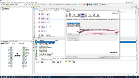
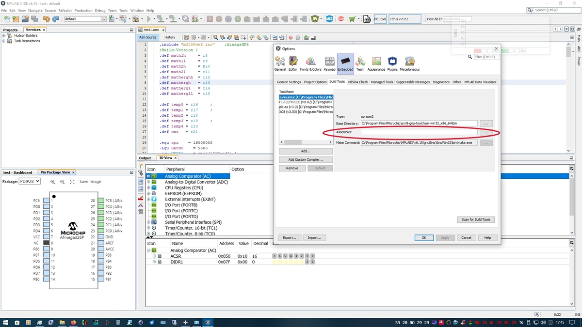
Code-Editor mit AVR Studio Projektansicht
test.asm, #include "m32def.inc", ATmega328P, Build-Version 1, Assembler, Analog Comparator (AC), ATmega328P
in „MPLAB X IDE AVR in ASM“ · Mikrocontroller und Digitale Elektronik · · Screenshots
-
Bild
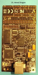
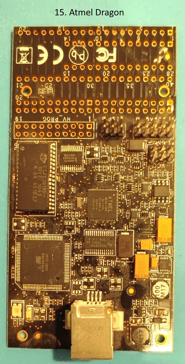
Atmel Dragon Debugger Platine
15. Atmel Dragon CE FC PB 21 23 25 28 20 30 35 19 HV_PROG 1 CXC10190 N 04 651537 ATMEL ATMEGA328 254112 ATMEL ATMEGA328 16AU 1133 100 M17 100 M17
in „[V] Sammlung diverser Entwicklungsboards“ · Markt · · Platinenfotos
-
Datei
ttester_110k_20140511.diff
the whole +# programs, if you call make or make upload. + +# Select your Part-No. for avrdude : +# atmega8 : m8 +# atmega168: m168 or m168p +# atmega328: m328 or m328p +# atmega1280: m1280 // see config.h for different port setting +# atmega2560: m2560 // see config.h for different port setting +PARTNO
-
Bild
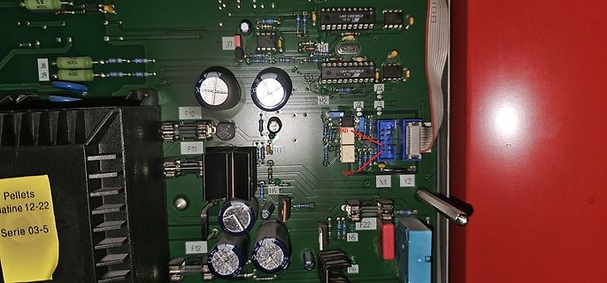
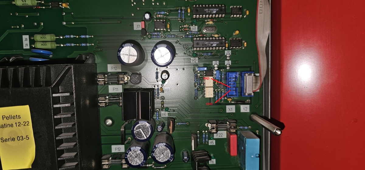
Nahaufnahme einer grünen Leiterplatte mit elektronischen Bauteilen
100K J8 J9 J7 ATMEGA328P ATMEGA328P F10 F11 F12 X1 X2 H1 H4 H5 F22 Pellets latine 12-22 Serie 03-5
in „Hargassner Pelletheizung Betriebsdatenerfassung“ · Haus & Smart Home · · Platinenfotos
-
PDF
ebike2_rev892_ATmega328PB.pdf
Hardware ~~~~~~~~~ - Pololu A-Star 328PB Micro Board mit ATmega32PB - Variante egal (3,3V/5V 16MHz/ 20MHz/etc...) (siehe https://www.pololu.com/category/239/a-star-328pb-micro) - Schaltplan: https://www.pololu.com/file/0J1463/ a-star-328pb-micro-schematic.pdf
in „Bosch E-Bike Antrieb Geschwindigkeitssensor“ · Fahrzeugelektronik ·
-
Bild
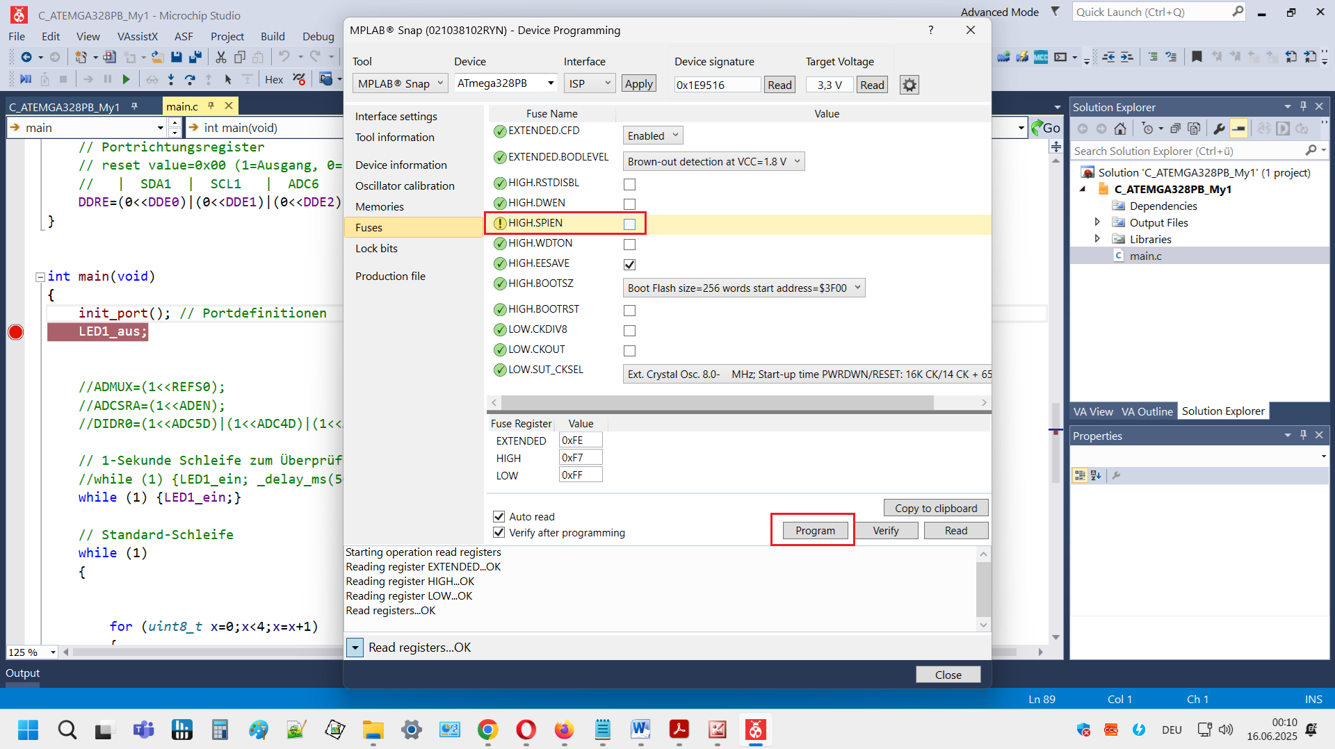
Microchip Studio Device Programming Fenster
C_ATMEGA328PB_My1 - Microchip Studio Device programming ATmega328PB ISP Apply Target Voltage 3,3 V Read Interface settings Device information Oscillator calibration Memories Fuses Lock bits Production file
in „ATMega328PB lässt sich nur noch programmieren. Sonst keine Funktion mehr“ · Mikrocontroller und Digitale Elektronik · · Screenshots
-
Bild
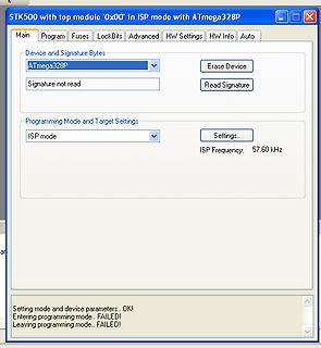
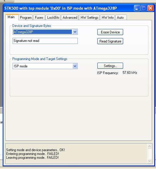
Software-Screenshot eines AVR-Programmierers
STK500 with top module '0x00' in ISP mode with ATmega328P Main Program Fuses LockBits Advanced HW Settings HW Info Auto Device and Signature Bytes ATmega328P Erase Device Signature not read Read Signature Programming Mode and Target Settings ISP mode
in „USP ISP Programmer läuft nicht“ · Mikrocontroller und Digitale Elektronik · · Screenshots
-
PDF
Compare_SCCB_ATmega_vs_STM32F429.pdf
Read Register 0x00 (ATmega328P <-> OV7670_with_FiFo) Read Register 0x00 (STM32F429 <-> OV7670_with_FiFo) Write Register 0x00, Value 0x88 (ATmega328P <-> OV7670_with_FiFo) Write Register 0x00, Value 0x88 (STM32F429 <-> OV7670
in „Brauche Unterstützung beim OV7670 (bzw. SCCB)“ · Mikrocontroller und Digitale Elektronik ·
-
Bild
Fehlermeldung beim Kompilieren eines AVR-Projekts
UART>make avr-gcc -c -gdwarf-2 -Os -Wall -Wstrict-prototypes -Wa,-adhlns=Test_CMPS14_UART.lst -mmcu=atmega328pb -std=gnu99 -I. Test_CMPS14_UART.c -o Test_CMPS14_UART.o unknown MCU 'atmega328pb' specified Known MCU names: at90s2313 at90s2323 at90s2333 at90s2343 attiny22 attiny26 at90s4414 at90s4433
in „WinAVR für ATmega328PB“ · Mikrocontroller und Digitale Elektronik · · Screenshots
-
Bild
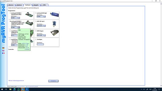
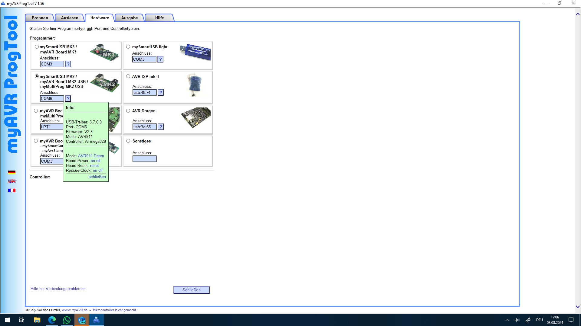
Screenshot der Software myAVR ProgTool V1.56
?, AVR ISP mk-II Anschluss usb 48:74 ?, Info: AVR Dragon Anschluss Port: COM 65 AVR Controller: ATmega328 Sonstiges Anschluss: Controller: ATmega328 Mode: AVR911 Board-Power: on off Board-Reset: reset Board-Clock: on off Rescue: close Schließen © SiSy Solutions GmbH, www.myAVR.de tiltrokocontroller
in „Atmega328 U(?) Prüfsummen Fehler“ · Mikrocontroller und Digitale Elektronik · · Screenshots
-
Bild
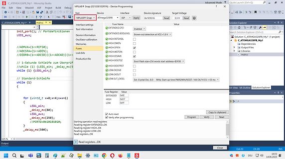
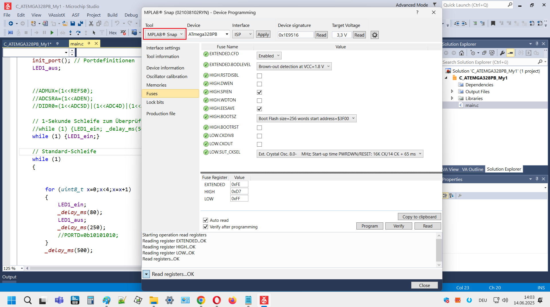
Software-Screenshot AVR Device Programming
C_ATMEGA328PB_My1 - Microchip Studio MPLAB Snap Device programming ATmega328PB Target Voltage 3,3 V Interface settings EXTENDED.BODLEVEL Enabled Brown-out detection at VCC= 1.8 V Fuses HIGH.DWEN SPIEN LOW.CKOUT
in „ATMega328PB lässt sich nur noch programmieren. Sonst keine Funktion mehr“ · Mikrocontroller und Digitale Elektronik · · Screenshots
-
PDF
myAVR_MK2b_zweiVersionen.pdf
AREF PC3(ADC3) 25 Suspend GND PC2(ADC2) FET1 PC1(ADC1) 24 USB C 29 PC6(/RESET) PC0(ADC0) 23 V GND ATMega328_QFP32 0 R1 1 0 C 1 10K CON1 ISP 6Pol. 3 0 4 K 5 K 6 K 1 0 1 Miso GND R 1 R 1 R 1 R 1 2 VCC 3 SCK 4 Mosi 2 K 3 K 1 2 n 5 /Res R 4 R 4 D o Dür 3 n 6 GND X20 L R L G D r L G 1 2 SDA R 2 X19 GND GND
in „myAVR MK2b fehlerhaft, Firmware / Hardware?“ · Mikrocontroller und Digitale Elektronik ·
-
Datei
PortBitList.h
ändern // Der Index ist jeweils die Arduino Pinnummer // UNO, Nano, Pro Mini usw. #if defined(__AVR_ATmega328P__) | defined(__AVR_ATmega328__) | defined(__AVR_ATmega168P__) | defined(__AVR_ATmega168__) constexpr uint8_t portBit[] = {0,1,2,3,4,5,6,7,0,1,2,3,4,5,0,1,2,3,4,5}; constexpr uint8_t pinMaske[]
in „C++ Klassenbibliothek für AVR“ · Mikrocontroller und Digitale Elektronik ·
-
PDF
Bitwackler.pdf
welchen Chip AVRDUDE flashen soll Hier gegeben für einen ATtiny2313: -p t2313 Beispiel für einen ATMega8: -p m8 Beispiel für einen ATMega168: -p m168 -c zu verwendender Programmer Hier gegeben: -c ponyser Beispiel für Programmer USBtinyISP: -c usbtiny Beispiel für Programmer USBasp -c usbasp Beispiel
in „Zeigt her eure "Grottenwerke"“ · Mikrocontroller und Digitale Elektronik ·
-
Datei
fraktal_speedtest_avr.c
fraktal_speedtest.c Testprogramm um festzustellen, wie schnell ein Apfelmaennchen berechnet werden kann MCU : ATmega328p Takt : 15.04.2025 R. Seelig ------------------------------------------------------ */ /* ------------------------------------------------------- In tftdisplay.h wird angegeben, wie das Display
in „CH32V003, float wirklich langsam?“ · Mikrocontroller und Digitale Elektronik ·
-
PDF
Transistortester092k.pdf
geändert (spart Platz bei der Darstellung). 3 11. Die Unterschiede in den Referenzspannungen derAtmega8,Atmega88,Atmega168 undAtmega328 werden jetzt nach Datenblatt berücksichtigt. Es besteht aber nach wie vor die Möglichkeit, per Schalter in der Makefile „WITH_AUTO_REF“ das Programm so zu kompilieren
-
PDF
AVRMicrocontrollers_Peripheral_Integration.pdf
ü ü ü ü 1 ü 1 6 (6) (6) (6) (6) (6) (6) ATmega48PB/88PB/168PB/328PB 32 4–32 0.5–2 1.8–5.5 20 10 8 ü ü ü 4 2/6 ü 2 1/3 ü ü ü ü 1/2 1/2 1/2 ü ü 6 ATmega80x/160x/320x/480x 28–48 8–48 1–6 1.8–5.5 20 10 16 ü ü ü 4 3 ü 5 ü ü ü ü ü ü 4 1 1 ü ü ü 3 ü ATmega64A
in „Nachfolger von Atmega169“ · Mikrocontroller und Digitale Elektronik ·
-
Datei
uhr_beschreibung.txt
##################################################################### Die Uhr wird mittels eines ATmega168 / 328p betrieben (getestet). Prinzipiell sollten auch ATmega48 und ATmega88 funktionieren (der compilierte Programmcode ist bei Verwendung von AVR-GCC Version 7.3.0 3950 Byte gross), allerdings sind diese beiden Controller ungetestet. Der Coretakt fuer den ATmega betraegt 8 MHz bei internem Takt. Die Fuses-Einstellungen hierfuer sind: ATmega168 : LoFuse = 0xE2, Hi-Fuse = 0xDF, Ex-Fuse = 0xF9 ATmega328p: LoFuse = 0xE2, Hi-Fuse = 0xD9, Ex-Fuse = 0xFF Das Uhrwerk
in „LED-Uhr mit Attiny26“ · Mikrocontroller und Digitale Elektronik ·
-
PDF
Vcc_Original_Info.pdf
1024 ? Reply ↓ majenko Post author August 24, 2016 at 9:58 am 1024. As per the datasheet for the ATMega328P section 24.7. “…0x3FF represents the selected reference voltage minus one LSB.” Reply ↓ Buzzy January 23, 2017 at 8:31 pm Correct value is 1023.0, since analogRead returns int (0 to 1023). *
in „Messen der uC_eigenen Ub mit Arduino Nano“ · Analoge Elektronik und Schaltungstechnik ·
-
Bild
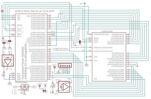
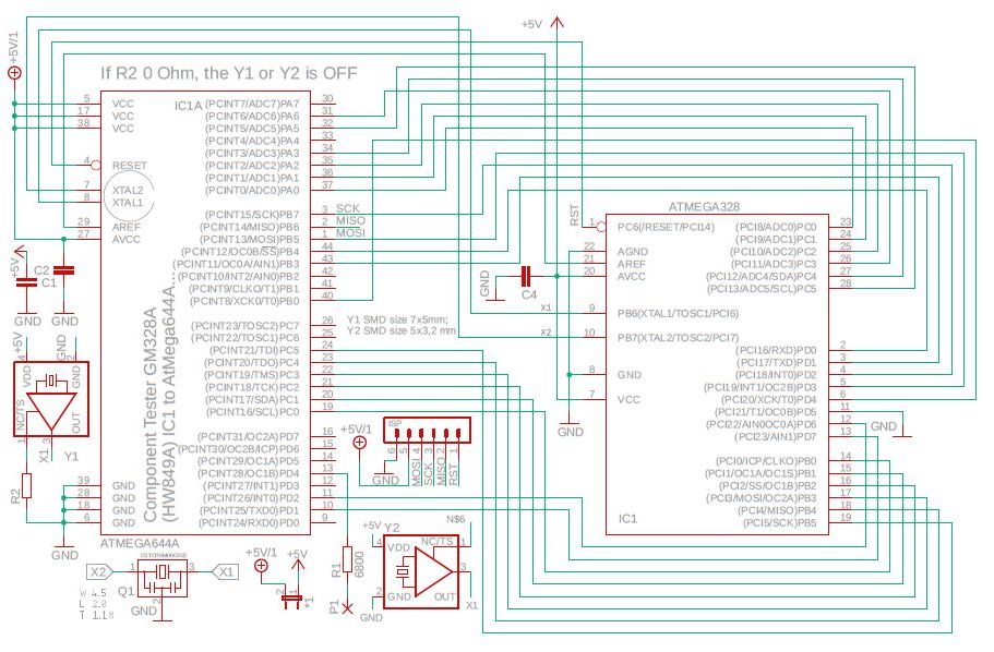
Schaltplan eines Mikrocontroller-basierten Komponenten-Testers
If R2 0 Ohm, the Y1 or Y2 is OFF +5V VCC RESET XTAL2 XTAL1 AREF AVCC GND NOCT OUT X1 R2 GND ATmega64A4 Component Tester GM328A (HW894A) IC1A (PCINT7/ADC7)PA7 (PCINT6/ADC6)PA6 (PCINT5/ADC5)PA5 (PCINT4/ADC4)PA4 (PCINT3/ADC3)PA3 (PCINT2/ADC2)PA2 (PCINT1/ADC1)PA1 (PCINT15/SCK)PB7 MISC MOSI (PCINT13/
in „Transistortester AVR“ · Projekte & Code · · Schaltpläne
-
Bild
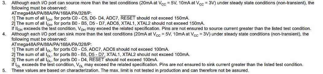
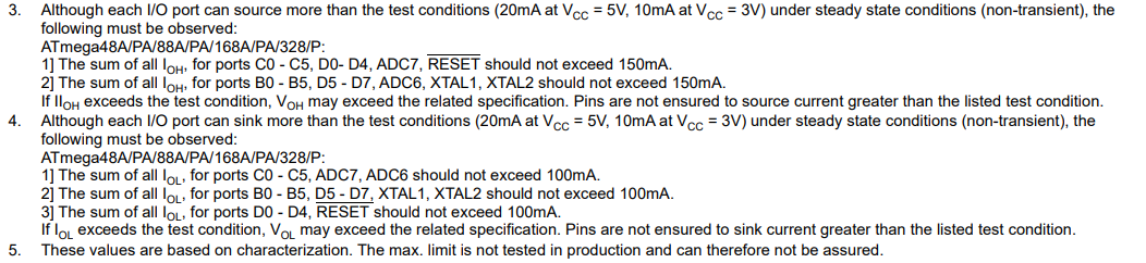
Textausschnitt aus einem Datenblatt
10mA at VCC = 3V) under steady state conditions (non-transient), the following must be observed: ATmega48A/PA/88A/PA/168A/PA/328P: 1] The sum of all IOH, for ports C0 - C5, D0 - D4, ADC7, RESET should not exceed 150mA. 2] The sum of all IOH, for ports B0 - B5, D5 - D7, ADC6, XTAL1, XTAL2 should not exceed
in „Ich messe 100mA für ein digital Pin auf dem Arduino Nano bei digitalWrite HIGH?“ · Mikrocontroller und Digitale Elektronik · · Screenshots
-
Datei
Bauelemente-Liste.txt
Menge Bezeichnung Bezugsquelle Bestellnummer 1 LCD-Anzeigemodul 2x16 Zeichen Pollin 120 422 1 µC ATmega 328 Reichelt ATMEGA 328P-PU 1 Low-Drop Festspannungsregler MCP1702 5V Reichelt MCP 1702-5002 1 Praezisionsspannungsquelle LM4040 2,5V Reichelt LM 4040 AIZ2,5 1 pnp-Transistor BC 557C Reichelt BC 557C
in „Info Platinen Bauteiletester / Transistortester“ · Markt ·
-
Datei
verlinkung.txt
+ - ATmega168A - - ATmega168P + - ATmega168PA - - ATmega169A - - ATmega169P + - ATmega169PA - # ATmega16A - - ATmega16M1 - - ATmega16U2 - - ATmega16U4 + - ATmega2560 + - ATmega2561 + * ATmega32 + - ATmega324A - - ATmega324P + - ATmega324PA + - ATmega325 + - ATmega3250 - - ATmega3250A + - ATmega3250P - - ATmega325A + - ATmega325P - - ATmega325PA + - ATmega328 - - ATmega328P + - ATmega329 + - ATmega3290 - - ATmega3290A
in „MC PIC - Warum diese Ungleichbehandlung?“ · Mikrocontroller und Digitale Elektronik ·
-
Datei
GSM_GPS_Shield.cpp
= 0; int sim_error = 0; int reg_OK = 0; char temp_in[10]; SPI spi=SPI(); // Arduino Duemilanove (ATmega328) & Arduino UNO (ATmega 328) GSM::GSM(int powerON_pin, int baud) { pinMode(powerON_pin, OUTPUT); // Pin 7 _powerON_pin = powerON_pin; _baud = baud; } void GSM::initializeGSM(char pwd[20]) { Serial.begin
in „Arduino + GSM-GPRS-GPS-Shield“ · Mikrocontroller und Digitale Elektronik ·
-
PDF
M12864_Transistor_Tester_Instructions.pdf
After all the welding jobs have been done, please connect the electric power instead of connecting Atmega328 and LCD(9V battery or external 5.5-12V DC power), and measuring the voltage of the pin7 and pin22 on the IC plug by using the multi-meter, and the voltage should be +5V(the button should be pushed
-
Datei
g__.txt
SimulatorStuff.h -fpermissive -x c++ -fverbose-asm -save-temps=obj -pthread -DF_CPU=10000000UL -D__AVR_ATmega328P__=1 -g -DSIMULATION -DCONST=/**/ -D__flash=/**/ -DPROGMEM=/**/ -I/usr/include/ -I/usr/lib/avr/include/ -c /home/inet/Entwicklung/KiCad/Projekte/Stiefelheizung/software/Simulator/uart-0Simulator.cpp
in „Linux/c++: errno in multithreaded Code“ · Softwareentwicklung ·
-
Datei
Timer1_25kHz.ino
OCR1B 0 */ void loop(void) { } void initPwmPin (const uint8_t pin) { switch(pin) { #if defined(__AVR_ATmega328P__) case 9: TCCR1A |= _BV(COM1A1); pinMode(pin, OUTPUT); break; // UNO Pin 9 case 10: TCCR1A |= _BV(COM1B1); pinMode(pin, OUTPUT); break; // UNO Pin 10 #endif #if defined(__AVR_ATmega2560__) case
in „AVR Timer1 Capture und Overflow gleichzeitig“ · Mikrocontroller und Digitale Elektronik ·
-
Datei
Bauelemente-Liste_v5_2_x.txt
120 422 - oder - LCD ohne Hintergrundbeleuchtung Reichelt LCD 162C (dann entfaellt "LCD-R") 1 µC ATmega 328 Reichelt ATMEGA 328P-PU 1 Low-Drop Festspannungsregler MCP1702 5V Reichelt MCP 1702-5002 - oder - LM 78L05 Reichelt µA 78L05 - oder - LM7805 Reichelt µA 7805 1 Praezisionsspannungsquelle LM336
in „Info Platinen Bauteiletester / Transistortester“ · Markt ·
-
Bild
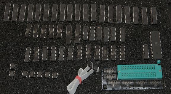
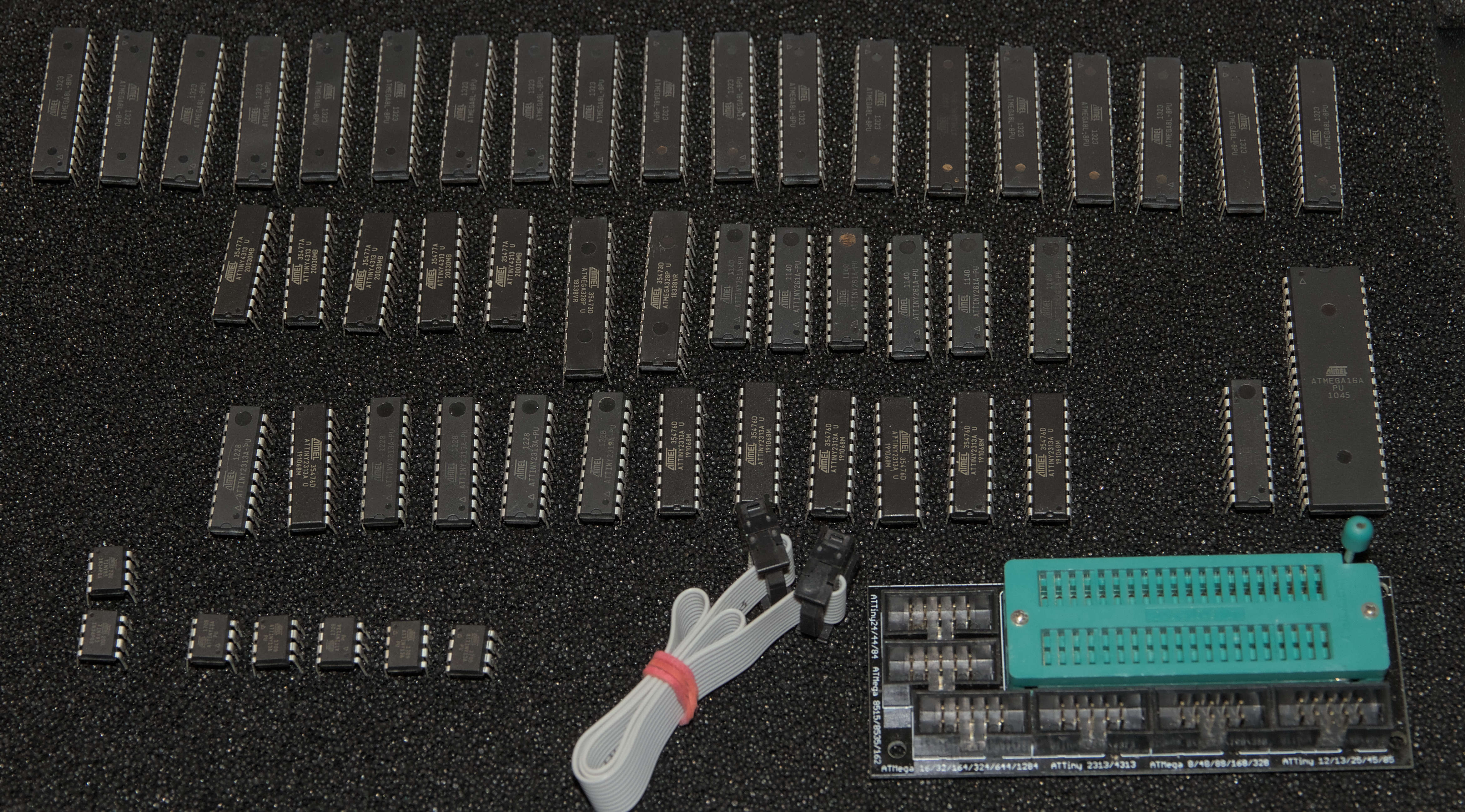
Verschiedene Mikrocontroller und ICs auf dunklem Untergrund
ATmega328P, ATmega168, ATmega8, ATmega4, ATmega16, ATmega32, ATmega64, ATmega128, ATmega2560, ATtiny2313, ATtiny45, ATtiny85
in „[V] Set: STK 500, Dragon, diverse ATtiny und -mega, passendes Buch, Zubehör“ · Markt · · Fotos
-
Datei
ini.asm
; Bernhard.Erfurt@gmx.de ; 01/2021 ; ; ; 128 x 64 Pixel=8.192 Pixel :8=1024 ; ATmega328P ; 8MHz ;.include "m328pdef.inc" .include "MACROS.asm" .equ TAKT = 8000000 ; 8 MHz ; ERROR CODES .equ ERROR_TWI_MT_START =0x20 .equ ERROR_TWI_MT_SLA =0x21 .equ ERROR_TWI_MT_DATA =0x22 .equ ERROR_TWI_MR_START
in „DEBO OLED2 0.96 0,96" OLED-Display SSD1306 SSD1312 Initialisierung TWI I2C AVR ATmeg8 Assembler ASM“ · Projekte & Code ·
-
Datei
ini.asm
; Bernhard.Erfurt@gmx.de ; 01/2021 ; ; ; 128 x 64 Pixel=8.192 Pixel :8=1024 ; ATmega328P ; 8MHz ;.include "m328pdef.inc" .include "MACROS.asm" .equ TAKT = 8000000 ; 8 MHz ; ERROR CODES .equ ERROR_TWI_MT_START =0x20 .equ ERROR_TWI_MT_SLA =0x21 .equ ERROR_TWI_MT_DATA =0x22 .equ ERROR_TWI_MR_START
in „DEBO OLED2 0.96 0,96" OLED-Display SSD1306 SSD1312 Initialisierung TWI I2C AVR ATmeg8 Assembler ASM“ · Projekte & Code ·
-
Datei
m328def.inc
" ;* Title : Register/Bit Definitions for the ATmega328 ;* Date : 2011-02-09 ;* Version : 2.35 ;* Support E-mail : avr@atmel.com ;* Target MCU : ATmega328 ;* ;* DESCRIPTION ;* When including this file in the assembly program file, all I/O register ;*
in „m328def.inc Datei für den ATmega328 bzw. ATmega328P gesucht“ · Mikrocontroller und Digitale Elektronik ·
-
PDF
AVR4100.pdf
ATmega48 X32K_1v8 MegaAVR ATmega48A X32K_1v8_ULP MegaAVR ATmega325P X32K_1v8_ULP MegaAVR ATmega325PA X32K_1v8_ULP MegaAVR ATmega328 X32K_1v8 MegaAVR ATmega328P X32K_1v8_ULP MegaAVR ATmega328PA X32K_1v8_ULP
in „Passende Kondensatoren für Uhrenquarz gesucht“ · Mikrocontroller und Digitale Elektronik ·
-
Datei
PartList_EZMkit.txt
Part List for EZM Kit (directory mega328_GM328R_kit) Name | Value | Comment -----+-------------+---- R1 | 680 Ohm | better 0.1% R2 | 470 kOhm | better 0.1% R3 | 680 Ohm | better 0.1% R4 | 470 kOhm | better 0.1% R5 | 680 Ohm | better 0.1% R6
-
Datei
mispav.htm
h3><a name="versionen"></a>Versionen</h3> <a href="../../../../h/home/html/etronik/atmel/atmel_c_atmega164p_324p_644p_doc7674.pdf">ATMega644P</a>: <a href="../../../../h/home/html/etronik/atmel/atmel_c_atmega164p_324p_644p_40002071A.pdf">(*)</a>: ROM: 64KiB 65536 (0x10000) Bytes, RAM:4KiB 4096 RAM <br> <a href="../../../../h/home/html/etronik/atmel/atmel_c_atmega328_328p_168a_168pa_88a_88pa_48a_48pa.pdf">Atmega328</a>: ROM: 32KiB 32768 (0x8000), RAM 2KiB 2048 <br> <a href="../../../../h/home/html/etronik/atmel/atmel_c_atmega32_complete_doc2503.pdf">Atmega32
in „Implementierung von Menüs auf alphanumerischen Displays“ · Mikrocontroller und Digitale Elektronik ·
-
Datei
Arduino_wdt.h
ATtiny24, ATtiny44, ATtiny84, ATtiny84A, ATtiny25, ATtiny45, ATtiny85, ATtiny261, ATtiny461, ATtiny861, ATmega48, ATmega88, ATmega168, ATmega48P, ATmega88P, ATmega168P, ATmega328P, ATmega164P, ATmega324P, ATmega644P, ATmega644, ATmega640, ATmega1280, ATmega1281, ATmega2560, ATmega2561, ATmega8HVA, ATmega16HVA
in „aktuelle AVR µC - wdt.h - kein RAMPD / CTRL / Enable Bit“ · Mikrocontroller und Digitale Elektronik ·
-
PDF
as5installer_stable-5.0.1038-readme-1.pdf
Full Control Full Full Full Control ATmega3250A Control Control ATmega3250P Full Control Full Full Full Control ATmega3250PA ATmega325A Full Full ATmega325P Full Control Full Full Full Control ATmega325PA Control ATmega328 Full Control Full Full Full Control ATmega328P Full Control Full Full Full Control ATmega329 Full Control Full Full Full Control ATmega3290 Full Control Full Full Full Control ATmega3290A Control Control ATmega3290P Full Control Full Full Full
in „AVR-Studio 5“ · Mikrocontroller und Digitale Elektronik ·
-
PDF
8-bit-MCU-Overview.pdf
2 1.8–5.5 20 10 12 8 2 1 1 1 1 1 3 ATtiny42x ATmega48PB/88PB/168PB 32 4–32 0.5–2 1.8–5.5 20 10 8 4 2/65) 2 1/3(5) 1/2(5) 1/2(1/2(5) (3) 6 /328PB ATmega80x/160x/320x /480x 28–48 8–48 1–6 1.8–5.5 20 10 16 4
in „Moderne AVR (Nachfolger Atmega und Attiny)“ · Mikrocontroller und Digitale Elektronik ·
-
PDF
8-bit-MCU-Overview.pdf
2 1.8–5.5 20 10 12 8 2 1 1 1 1 1 3 ATtiny42x ATmega48PB/88PB/168PB 32 4–32 0.5–2 1.8–5.5 20 10 8 4 2/65) 2 1/3(5) 1/2(5) 1/2(1/2(5) (3) 6 /328PB ATmega80x/160x/320x /480x 28–48 8–48 1–6 1.8–5.5 20 10 16 4
in „AVR®DD family, low pin count devices“ · Mikrocontroller und Digitale Elektronik ·
-
PDF
8-bit-MCU-Overview.pdf
2 1.8–5.5 20 10 12 8 2 1 1 1 1 1 3 ATtiny42x ATmega48PB/88PB/168PB 32 4–32 0.5–2 1.8–5.5 20 10 8 4 2/65) 2 1/3(5) 1/2(5) 1/2(1/2(5) (3) 6 /328PB ATmega80x/160x/320x /480x 28–48 8–48 1–6 1.8–5.5 20 10 16 4
in „AVR®DD family, low pin count devices“ · Mikrocontroller und Digitale Elektronik ·
-
PDF
avrdude.pdf
m324p ATmega324P m324pa ATmega324PA m325 ATmega325 m3250 ATmega3250 m328 ATmega328 m328p ATmega328P m329 ATmega329 m3290 ATmega3290 m3290p ATmega3290P m329p ATmega329P m32u2 ATmega32U2 m32u4 ATmega32U4 m48 ATmega48
in „AVRDude als Tool in AVR Studio 4 einbinden“ · Mikrocontroller und Digitale Elektronik ·
-
Datei
Arduino_Drehgeber.ino
einem AVR: spezielle Version fuer Arduino UNO R3! Das gezeigte C-Beispielprogramm laeuft auf einem ATmega328. Hier wurde testweise ein Arduino UNO R3 verwendet, da ohne grosse Loeterei Stromversorgung und Datenausgabe ueber den USB-Anschluss erledigt werden. Zum Test wurde ein mechanischer Drehgeber verwendet
in „Drehgeber per Interrupt auswerten, AVR“ · Projekte & Code ·
-
Datei
TimerOne.h
/* * Interrupt and PWM utilities for 16 bit Timer1 on ATmega168/328 * Original code by Jesse Tane for http://labs.ideo.com August 2008 * Modified March 2009 by Jérôme Despatis and Jesse Tane for ATmega328 support * Modified June 2009 by Michael Polli and Jesse
in „Rotary Encoder macht immer 4 Schritte“ · Mikrocontroller und Digitale Elektronik ·
-
Datei
Timer.h
Mcucpp * **************************************************************************** * ..\mcucpp\AVR\ATmega-164-324-644-1284\Timer.h * ********************************************** * modified: based on a concept used in ..\mcucpp\AVR\attiny|atmega...\usart.h * ******** * * **************************************************************************** * ATmega164A/PA/324A/PA/644A/PA/1284(*)/P(*) HAS TIMER D,D,H,H(*) * **************************************************************************** * ATmega48A-48PA-88A-88PA-168A-168PA-328-328P HAS TIMER D,D,H
in „Knoten im Kopf, Klassen und Vererbung“ · Mikrocontroller und Digitale Elektronik ·
-
PDF
DemystifyingtheTLC5940.pdf
multiple TLC5940 chips in series 69 iii iv CONTENTS List of Figures 2.1 Connecting a TLC5940 to an ATmega328P . . . . . . . . . . . . . . . . . .8 B.1 Connecting two TLC5940 chips in series . . . . . . . . . . . . . . . . . 70. . v vi LIST OF FIGURES Chapter 1 Introduction This book explains how to turn
in „System Clock Output mit Atmega32“ · Mikrocontroller und Digitale Elektronik ·
-
PDF
DemystifyingtheTLC5940.pdf
multiple TLC5940 chips in series 69 iii iv CONTENTS List of Figures 2.1 Connecting a TLC5940 to an ATmega328P . . . . . . . . . . . . . . . . . .8 B.1 Connecting two TLC5940 chips in series . . . . . . . . . . . . . . . . . 70. . v vi LIST OF FIGURES Chapter 1 Introduction This book explains how to turn
in „TLC5940 library: Erfassen von Veränderungen“ · Mikrocontroller und Digitale Elektronik ·
-
PDF
Timer_1_Fast_Mode_erklaert.pdf
Hallo, ATmega328P Manual Version DS40002061B. Nun denn. Die Frequenz habe ich jetzt mal mit 100Hz festgelegt. Die Einstellungen sehen dann wie unten aus. Wie kommt man darauf? Timer 1 Tabelle auf Seite 141-142.

in „Timer Arduino Einsatzgebiete“ · Mikrocontroller und Digitale Elektronik ·