-
Datei
PWM.asm
****************************************************************** ;* Programm PWM.ASM ;* ;* Für ATtiny13 im Auslieferungszustand ( High = $FF ; Low = $6A ) ;* ;* ;* Der PWM-Pinn 5 ( OC0A ) soll die höchstmögliche Rechteckfrequenz liefern die der ;* ATtiny13 im Auslieferungszustand erzeugen kann ( Ca
in „ATtiny13 im Fast PWM-Mode 7 als Rechteckgenerator“ · Mikrocontroller und Digitale Elektronik ·
-
Datei
kueche_2.lst
mov r25, r24 0000e4 9582 swap r24 0000e5 d001 rcall usart_putlo 0000e6 2f89 mov r24, r25 usart_putlo: 0000e7 708f andi r24, $0F 0000e8 6380 ori r24, '0' 0000e9 338a cpi r24, '9'+1 0000ea f350 brlo usart_put 0000eb
-
Datei
Netzmessung_TWI.cpp
on the ATmega2560 http://openenergymonitor.org/emon/node/2253#comment-11432 #elif defined (__AVR_ATtiny24__) || defined(__AVR_ATtiny44__) || defined(__AVR_ATtiny84__) ADMUX = _BV(MUX5) | _BV(MUX0); #elif defined (__AVR_ATtiny25__) || defined(__AVR_ATtiny45__) || defined(__AVR_ATtiny85__) ADMUX = _BV(
in „AVR Frequenzmessung, DS18S20“ · Mikrocontroller und Digitale Elektronik ·
-
Datei
Neu_Text_file.txt
ORI R30,LOW(@0) ORI R31,HIGH(@0) ORI R22,BYTE3(@0) ORI R23,BYTE4(@0) .ENDM .MACRO __DELAY_USB LDI R24,LOW(@0) __DELAY_USB_LOOP: DEC R24 BRNE __DELAY_USB_LOOP .ENDM .MACRO __DELAY_USW LDI R24,LOW(@0) LDI R25,HIGH(@0) __DELAY_USW_LOOP: SBIW R24,1 BRNE __DELAY_USW_LOOP .ENDM .MACRO __CLRD1S CLR R30 STD
in „CodeVision Einsteiger“ · Mikrocontroller und Digitale Elektronik ·
-
PDF
ir-detect.pdf
IR-Bewegungsmelder für Luxeon-LEDs Mit einem kleinen IR-Bewegungsmelder von Panasonic und einem ATTiny25 ist diese kleine Platine ausgestattet, welche durch Infrarotstrahlungen Bewegungen erkennt und eine Luxeon- LED ansteuert. Praktische Anwendungen wären Gehwege oder wie bei mir der Treppenaufgang
in „Atmega8 an zwei Knopfzellen betreiben (6V)“ · Mikrocontroller und Digitale Elektronik ·
-
 Bild
Bild
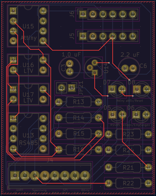
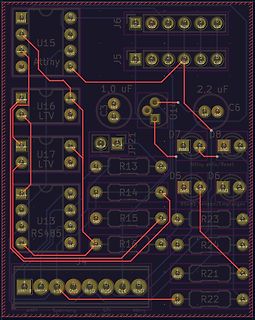
CAD-Ansicht eines Leiterplatten-Layouts
U15 Attiny, J6, 1 RISE, 2 GND, 3 CLK, 4 NO, 5 SDA, 6 SCL, J5, 1 TX, 2 GND, 3 CLK, 4 NO, 5 SDA, 6 SCL, 2,2 uF, C6, 1,0 uF, U16 LTV, U17 LTV, D7, D8, 1 RISE, 1 GND, JP21, R13, R14, D5, D6, 1 GND, 1 MISC, R15, R16, R23, R24, U13 RS485, 1 GND, 2 TX, 3 RX, 4 GND, R21, R22, 1 UART-B, 2 UART-A, 3 5V, 4 GND, 5 MOSI, 6 CLK, 7 RESET, 1 SPI, Attiny, UART, Spannung, MOSI, MISO, RX, TX
in „BME280 mit Attiny85 auslesen Daten per SN75176 an Pi senden“ · Mikrocontroller und Digitale Elektronik · · Layouts
-
PDF
DALI_readme_151001.pdf
integrierter DALI-Schnittstelle. Damit habe ich gearbeitet. Das Projekt besteht aus 2 Teilen: Der Hardware (ATTiny2313), programmiert in C und einem User-Interface, realisiert mit Python / TKinter. 1.) Hardware + C-Programm EinATTiny2313 fungiert als Gateway zwischen serieller Schnittstelle und dem DALI-Bus. Der
in „RS232-DALI-Gateway für ATtiny2313 / Python-GUI“ · Projekte & Code ·
-
 Bild
Bild
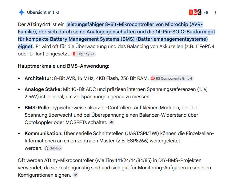
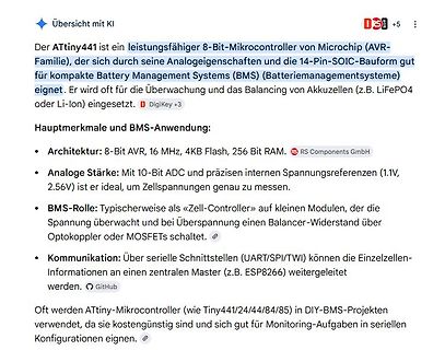
Text über ATtiny441 Mikrocontroller und BMS-Anwendung
Übersicht mit KI Der ATtiny441 ist ein leistungsfähiger 8-Bit-Mikrocontroller von Microchip (AVR-Familie), der sich durch seine Analogeigenschaften und die 14-Pin-SOIC-Bauform gut für kompakte Battery Management Systems (BMS)
in „alternativ Akku zum verbauten??“ · Analoge Elektronik und Schaltungstechnik · · Screenshots
-
 Bild
Bild
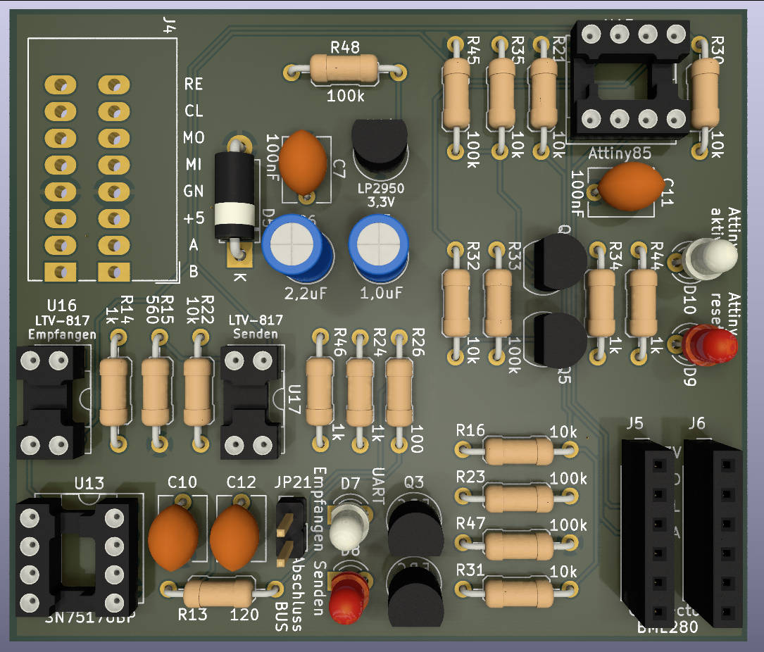
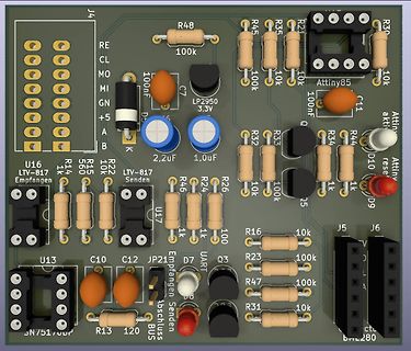
CAD-Ansicht eines Leiterplatten-Layouts
J4 R48 R45 R35 R21 R30 100k 10k 10k RE CL MO MI GN +5 A B K 100nF C7 LP2950 3,3V 100nF C11 Attiny85 Attiny akti D10 R34 R44 R33 R32 10k 10k 1k 1k 1k Q5 D9 R26 R24 R46 100 1k 1k LTV-817 Senden LTV-817 Empfangen U17 R15 560 R14 1k U16 R22 10k U13 C10 C12 JP21 Empfangen Senden Abschluss BUS UART R16
in „BME280 mit Attiny85 auslesen Daten per SN75176 an Pi senden“ · Mikrocontroller und Digitale Elektronik · · Layouts
-
Datei
display.asm
************************************************************ .include "tn2313def.inc" ;Prozessor ATTINY2313 ; ATtiny2313 Display TC1602A 4 bit Mode ; +--+-+--+ 2 Zeilen zu je 16 Stellen ; !RESET | |_| | VCC Memoryadr.: Zeile1: 00 und Zeile2: 40h ; (RX)PD0 | | PB7(SCK) n.c. ; (TX)PD1 | | PB6(MISO) n.c
in „LCD Routine Funktioniert nicht“ · Mikrocontroller und Digitale Elektronik ·
-
Datei
fuse.c
programmable attinys * . reset hi-low fuses to factory default on target devices * . layout to drop-on attiny13, attiny25/45/85 8 pin devices targets * . attiny24/44/84 targets needs additional breadboard and jumper wires * . standalone operations, fuses show on 7 segment display * * . project fuse setting
in „Attiny85 neu verfust?“ · Mikrocontroller und Digitale Elektronik ·
-
Datei
STRREV.S
// ***** Prüfung der Funktion strrev ***** // // Parameter 1 wird in r24:r25 übergeben und enthält die Stringadresse // Rueckgabewert in r24:r25 // // .global strrev26 .func strrev26 strrev26: mov r26, r24 ; Parameter 1 = Stringadresse, nach X kopieren mov r27, r25 mov r30
in „Problem mit ltoa“ · Mikrocontroller und Digitale Elektronik ·
-
Datei
diff-20100823.txt
/lcd_hd44780u.h 2010-08-22 16:56:56.000000000 +0200 +++ freq_meter-20100823/lcd_hd44780u.h 2010-08-24 00:20:01.000000000 +0200 @@ -80,6 +80,8 @@ static inline void lcd_write4 (uint8_t d // RW setup time t_AS: min 40ns (60ns) - considered already set LCDC_PORT |= (1<<LCD_E); // Total E high PW_EH: min
in „Reziproker Frequenzzähler+ Optimierte 64bit uint Routinen“ · Projekte & Code ·
-
Datei
Recalibrate_Clock.asm
by watchdog interrupt measure: clr r24 clr r25 wdr delay: ldi r18,LOW(int(bclock*16)) delay1: dec r18 brne delay1 adiw r25:r24,1 rjmp delay last_step: sub r24,r2 ;get difference between current value and target value sbc r25,r3 brpl last_step1 com r25 ;negate result to get positive difference value neg r24 sbci r25,-1 last_step1: cp r4,r24 ;compare with previous value to check which one is closer to target clock cpc r5,r25 brcc clk_defined ;jump if current value is closest sbrc r17,7 dec r16 ;revoke previous
in „ATtiny Clock Recalibration ohne externe Referenz“ · Projekte & Code ·
-
PDF
Grillen_Fuchs_Beschreibung_V1_0.pdf
PB1-Pin einfach offen. DerATTINY wird in den Pausen zwischen dem Senden immer in den Power-Down-Modus versetzt. Die Stromaufnahme der gesamten Schaltung beträgt dann etwa 5uA. Wenn im Code das #define PAUSE vergrößert wird, so kann
in „ATTINY 433MHz Fuchssender mit akustischem Grillen-Sound“ · Projekte & Code ·
-
PDF
Grillen_Fuchs_Beschreibung_V1_1.pdf
PB1-Pin einfach offen. DerATTINY wird in den Pausen zwischen dem Senden immer in den Power-Down-Modus versetzt. Die Stromaufnahme der gesamten Schaltung beträgt dann etwa 5uA. Wenn im Code das #define PAUSE vergrößert wird, so kann
in „ATTINY 433MHz Fuchssender mit akustischem Grillen-Sound“ · Projekte & Code ·
-
Datei
tn85def.inc
" ;* Title : Register/Bit Definitions for the ATtiny85 ;* Date : 2007-02-28 ;* Version : 2.24 ;* Support E-mail : avr@atmel.com ;* Target MCU : ATtiny85 ;* ;* DESCRIPTION ;* When including this file in the assembly program file, all I/O register ;* names
in „Peter Danneggers Bootloader (fastboot) für AVR-GCC-Toolchain“ · Projekte & Code ·
-
PDF
readme_151223.pdf
integrierter DALI-Schnittstelle. Damit habe ich gearbeitet. Das Projekt besteht aus 2 Teilen: Der Hardware (ATTiny2313), programmiert in C und einem User-Interface, realisiert mit Python / TKinter. 1.) Hardware + C-Programm EinATTiny2313 fungiert als Gateway zwischen serieller Schnittstelle und dem DALI-Bus. Der
in „RS232-DALI-Gateway für ATtiny2313 / Python-GUI“ · Projekte & Code ·
-
Datei
timing.cpp
volatile unsigned long timer2_millis = 0; static unsigned char timer2_fract = 0; #if defined(__AVR_ATtiny24__) || defined(__AVR_ATtiny44__) || defined(__AVR_ATtiny84__) SIGNAL(TIM2_OVF_vect) #else SIGNAL(TIMER2_OVF_vect) #endif { // copy these to local variables so they can be stored in registers // (volatile
in „IRMP - Infrared Multi Protocol Decoder“ · Projekte & Code ·
-
Datei
Synth.asm
.nolist .include "tn2313def.inc" ; Define device ATtiny2313 .list ; ***Konstanten*** .equ F_CPU = 10000000 .equ F_ICR = 256 .equ PWM = F_CPU/F_ICR .equ BAUD = 31250 .equ BRC = (F_CPU/16/BAUD)-1 .equ MAXBUF = 40 ; ***Defs*** .def rsreg = r15 .def rmp = r16
in „Attiny2313 Timer16 Bit, Normal Mode, unsauber“ · Mikrocontroller und Digitale Elektronik ·
-
Datei
attiny2313.c
/******************************************************* Projekt: DP Lüftersteuerung Version : ATTiny2313A - 1 Erstellt: 22.10.2016 Letze Änderung: 24.10.2016 Chip: Attiny2313A mit internen 8.0 MHz *******************************************************/ /// Header-Dateien /// #include <io.h> #include <delay.h> /// #define /// // Kommunikation (Daten vom Attiny25 empfangen) #define InterruptIn PIND.2 #define DataIn PINA.0 //7-Segment-Anzeigen #define SegmentA PORTB.7 #define SegmentB PORTB.6 #define SegmentC PORTB.5 #define SegmentD PORTB.4 #define SegmentE
in „Attiny2313A - Timer Interrupt wird nicht aufgerufen (C)“ · Mikrocontroller und Digitale Elektronik ·
-
Datei
Synth.asm
.nolist .include "tn2313def.inc" ; Define device ATtiny2313 .list .macro WriteSram ; (register, const) ldi XL, low(SRAM_START) ldi XH, high(SRAM_START) ldi rmp, 0 j0: cpi rmp, @1 breq j1 st X+, @0 inc rmp rjmp j0 j1: ldi XL, low(SRAM_START) ldi XH, high
in „Attiny2313 Timer16 Bit, Normal Mode, unsauber“ · Mikrocontroller und Digitale Elektronik ·
-
Datei
iotn104.h
DAMAGE. ****************************************************************************/ #ifndef _AVR_ATTINY104_H_INCLUDED #define _AVR_ATTINY104_H_INCLUDED #ifndef _AVR_IO_H_ # error "Include <avr/io.h> instead of this file." #endif #ifndef _AVR_IOXXX_H_ # define _AVR_IOXXX_H_ "iotn104.h" #else # error "
in „Neuer ATtiny104?“ · Mikrocontroller und Digitale Elektronik ·
-
Datei
avrdragon_device_support.html
SCKT3400D1">SCKT3400D1</a></td><td rowspan="1" colspan="1"></td></tr><tr><td rowspan="1" colspan="1">ATtiny12</td><td rowspan="1" colspan="1"></td><td rowspan="1" colspan="1">x</td><td rowspan="1" colspan="1">x</td><td rowspan="1" colspan="1"></td><td rowspan="1" colspan="1"></td><td rowspan="1" colspan=
in „Welches Programmiergerät soll ich mir kaufen?“ · Mikrocontroller und Digitale Elektronik ·
-
Datei
dude511.txt
unknown) avrdude: Recv: . [1f] Device code: 0x1f = (unknown) avrdude: Recv: [20] Device code: 0x20 = ATtiny84 avrdude: Recv: ! [21] Device code: 0x21 = (unknown) avrdude: Recv: " [22] Device code: 0x22 = (unknown) avrdude: Recv: # [23] Device code: 0x23 = (unknown) avrdude: Recv: $ [24] Device code: 0x24
in „avrdude - Probleme unter Mac OS X 10.7 (Lion)“ · Mikrocontroller und Digitale Elektronik ·
-
Datei
dude511_mit_arduino_conf.txt
unknown) avrdude: Recv: . [1f] Device code: 0x1f = (unknown) avrdude: Recv: [20] Device code: 0x20 = ATtiny84 avrdude: Recv: ! [21] Device code: 0x21 = (unknown) avrdude: Recv: " [22] Device code: 0x22 = (unknown) avrdude: Recv: # [23] Device code: 0x23 = (unknown) avrdude: Recv: $ [24] Device code: 0x24
in „avrdude - Probleme unter Mac OS X 10.7 (Lion)“ · Mikrocontroller und Digitale Elektronik ·
-
Datei
fernbedienung.bas
*********** 'Aufgabe : RC5-Empfänger 'Compiler : BASCOM-AVR 'Hardware : TSOP1736 an PB.0 'Chip : ATTiny 2313 '******************************************************************* $regfile = "m8def.dat" 'bzw. Attiny2313.dat $crystal = 4000000 'internal clock 4MHz $hwstack = 32 $swstack = 10 $framesize
in „rc5 mit attiny 2313“ · Mikrocontroller und Digitale Elektronik ·
-
Datei
Einschaltverzoegerung.asm
crystal ;* ;*************************************************************************** .device ATtiny2313 .include "tn2313def.inc" ;ATTiny2313 ;.include "2313def.inc" ;90S2313 .equ Bit0 =0 .equ Bit1 =1 .equ Bit2 =2 .equ Bit3 =3 .equ Bit4 =4 .equ Bit5 =5 .equ Bit6 =6 .equ Bit7 =7 .def temp =R18 .def Delay1 =r23 .def Delay2 =r24 .def Delay3 =r25 .def zeit =r26 .CSEG .ORG 0x00 ;rjmp reset ldi temp,RAMEND ;Initialize stackpointer out SPL,temp ;output Alle auf 11111111 ldi temp,0x00 out portd,temp ldi temp,0xff out DDRD,temp ;
in „Attiny 2313 Einschaltverhalten der Ports“ · Mikrocontroller und Digitale Elektronik ·
-
Datei
dude5.4arduino_avr910.txt
0x1d = (unknown) Device code: 0x1e = (unknown) Device code: 0x1f = (unknown) Device code: 0x20 = ATtiny84 Device code: 0x21 = (unknown) Device code: 0x22 = (unknown) Device code: 0x23 = (unknown) Device code: 0x24 = (unknown) Device code: 0x25 = (unknown) Device code: 0x26 = (unknown) Device code: 0x27
in „avrdude - Probleme unter Mac OS X 10.7 (Lion)“ · Mikrocontroller und Digitale Elektronik ·
-
Datei
dude5.6_avr910.txt
0x1d = (unknown) Device code: 0x1e = (unknown) Device code: 0x1f = (unknown) Device code: 0x20 = ATtiny84 Device code: 0x21 = (unknown) Device code: 0x22 = (unknown) Device code: 0x23 = (unknown) Device code: 0x24 = (unknown) Device code: 0x25 = (unknown) Device code: 0x26 = (unknown) Device code: 0x27
in „avrdude - Probleme unter Mac OS X 10.7 (Lion)“ · Mikrocontroller und Digitale Elektronik ·
-
Datei
dude54arduino.txt
0x1d = (unknown) Device code: 0x1e = (unknown) Device code: 0x1f = (unknown) Device code: 0x20 = ATtiny84 Device code: 0x21 = (unknown) Device code: 0x22 = (unknown) Device code: 0x23 = (unknown) Device code: 0x24 = (unknown) Device code: 0x25 = (unknown) Device code: 0x26 = (unknown) Device code: 0x27
in „avrdude - Probleme unter Mac OS X 10.7 (Lion)“ · Mikrocontroller und Digitale Elektronik ·
-
Datei
dds.asm
****************************************************************** ; ; ; ; Output frequency (using 24 bit accumulator) : ; ; f = deltaPhase * fClock/2^24 ; ; fClock is in this case the CPU clock divided by the ; number of cycles to output the data ( 9 cycles ) ; ; f = r24/r25/r26 * (11059200/9)/16777216
in „ASM von MiniDDS in WinAVR kompilieren. Wie?“ · Mikrocontroller und Digitale Elektronik ·
-
Datei
Temp.asm
clk/4= abt. 1kHz ;*************************************************************************** ; ATtiny26 Pin Assignment: ; 01 PB.0 MOSI/ CW-Tone-out ; 02 PB.1 MISO ; 03 PB.2 SCK ; 04 PB.3 OC1B MotDrive(U) ; 05 Vcc ; 06 Gnd ; 07 PB.4 AD7/RS232negVoltChgPump (T0) ; 08 PB.5 AD8 ; 09 PB.6 AD9/RS232 TxD-
in „Tiny26 Programm ändern in Programm für Mega8“ · Mikrocontroller und Digitale Elektronik ·
-
 Bild
Bild
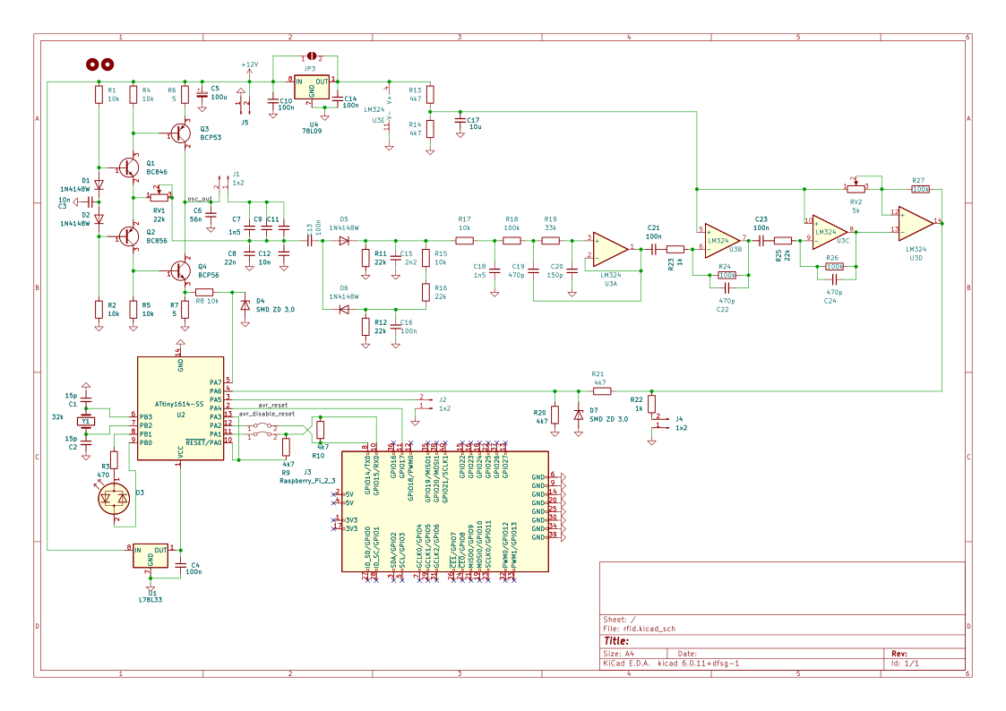
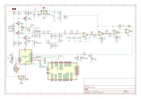
Schaltplan mit Raspberry Pi und Verstärkerschaltung
+12V, J3, D7, R13, C14, U4, TL09, R17, R18, C21, C23, LM324, U3, R27, R2, R19, R24, C22, C24, R25, R22, R20, R26, R10, R9, R7, R5, R4, R1, R16, R15, R14, R11, R8, R6, R3, C10, C5, C7, C8, C12, C15, C16, C19, C20, C21, C22, C23, C24, Q1, Q2, Q3, D1, D2, D4, D5, D6, U2, ATtiny164-55,
in „Bitte nicht nachmachen: PE des DSO abkleben?“ · Analoge Elektronik und Schaltungstechnik · · Schaltpläne
-
Datei
tn2313def.inc
" ;* Title : Register/Bit Definitions for the ATtiny2313 ;* Date : 2006-10-03 ;* Version : 2.24 ;* Support E-mail : avr@atmel.com ;* Target MCU : ATtiny2313 ;* ;* DESCRIPTION ;* When including this file in the assembly program file, all I/O register
in „Timer Compare Interrupt Attiny2313“ · Mikrocontroller und Digitale Elektronik ·
-
Datei
ATtiny85_RDA5807_Radio.c
/************************************************************************** ATtiny85_RDA5807_Radio: UKW Stereo Empfänger mit dem Modul RDA5807M mit OLED I2C Display 64x128 und 3 Tasten zur Steuerung Ressourcen: ATtiny85 @8MHz intern, Fuses Low=E2, High=DF Pinbelegung: PB0=SDA, PB1
in „(sehr) kleines "FrameWork" für ATtiny44“ · Projekte & Code ·
-
Datei
VirtualWire.cpp
defined #endif #include "VirtualWire.h" #include <util/crc16.h> #undef TIMER_VECTOR #ifdef __AVR_ATtiny85__ # define TIMER_VECTOR TIM0_COMPA_vect #elif defined(__AVR_ATtiny84__) || defined(__AVR_ATtiny24__) || defined(__AVR_ATtiny44__) // Why can't Atmel make consistent? # define TIMER_VECTOR TIM1_COMPA_vect
in „Korrigierte "VirtualWire" Library für Attiny84 / 85“ · Projekte & Code ·
-
PDF
DE200610__1_.pdf
einfach zu installieren und zu bedienen ATTINY 24-20 PU DIL-14 20 12 · CPU-Versorgung: 1,65 - 1,95 V / 3,0 - 3,6 V · Analog-Eingänge: 8 Single-ended- oder ATTINY 24-20 SSU SOIC-14 20 12 · I/O-Versorgung: 3,0 - 3,6 V 4 differenzielle 12-bit-Analog-Eingänge / gemischt ATTINY 24V-10 PU DIL-14 10 12 · Fast-I²C / 2 UARTs / 2 SPIs / PWM · ±20 V Eingangs-Bereich, 12 bit Auflösung ATTINY 24V-10 SSU SOIC-14 10 12 je 1. 70 · 4x 32bit-Timer inkl. RTC und Watchdog ·Präzisions-PGA
in „ekg schaltung aus heft 10/2006“ · Analoge Elektronik und Schaltungstechnik ·
-
PDF
avr-libc-user-manual.pdf
atmega169 • atmega32 • atmega323 • atmega64 [untested] • atmega8515 [untested] • atmega8535 [untested] ATtiny Type Devices: • attiny11 [1] • attiny12 [1] • attiny15 [1] • attiny22 • attiny26 • attiny28 [1] Misc Devices: • at94K [2] • at76c711 [3] • at43usb320 • at43usb355 • at86rf401 Generated on Wed Nov 26
in „C Tutorial gesucht“ · Mikrocontroller und Digitale Elektronik ·
-
PDF
AVR042_Hardware_Design_Considerations_doc2521.pdf
target application board so that the ISP connectors can be accessed easily. Note: 1. Except the ATtiny10, ATtiny11 and ATtiny28. On most devices the ISP interface is located on the same pins as the SPI interface. However, there are exceptions from this rule, e.g. the ATmega103 and the ATmega128 do not
in „Atmega 8A PU“ · Mikrocontroller und Digitale Elektronik ·
-
Datei
Drehimpusgeber_V3.asm
1? nein... rcall dec_cnt_dgb ;sbiw r24:r25, 1 ;ja, subtrahieren sbrc r17, 1 ;Richtung 2? nein... rcall inc_cnt_dgb ;adiw r24:r25, 1 ;ja, addieren rjmp end_drehgeber ;ende inc_cnt_dgb: cp r24, r16 cpc r25, r18 breq clr_cnt_dgb adiw r24:r25
-
Datei
Slave.bas
, Data_rx 'Waitms 500 '********************* Loop End I2c_start: Push R16 Push R20 Push R23 Push R24 Usisr = &B01001111 Bitwait Usisr.6 , Set 'Warte bis Start kondition fertig I2c_mode = 0 Sda_dir = 0 'SDA Input Usicr = &B11111000 'i2c Config Usisr = &B11110000 'Reset Flags pop R24 pop R23 pop R20 pop
in „Register in BASCOM“ · Mikrocontroller und Digitale Elektronik ·
-
Datei
iotn841.h
DAMAGE. ****************************************************************************/ #ifndef _AVR_ATTINY841_H_INCLUDED #define _AVR_ATTINY841_H_INCLUDED #ifndef _AVR_IO_H_ # error "Include <avr/io.h> instead of this file." #endif #ifndef _AVR_IOXXX_H_ # define _AVR_IOXXX_H_ "iotn841.h" #else # error "
in „Neue ATtinies 441 und 841“ · Mikrocontroller und Digitale Elektronik ·
-
PDF
Schaltplan.pdf
1 2 3 4 X5 schwarz 1 rot 2 gelb C14 3 100n JST B3B-EH_A X2 X6 GND 1 A +24V 2 A D3 LM2576 +12V...6V 2 L1 C15 3 1 OUT 100n JST B3B-EH_A +24V Vin 4 V3 150µH C9 C10 R9 X7 C8 Feedback 1N5818 470u 470u 18k 100u GND ON/OFF 1 2 3 5 3 D4 TPS5420D L2 100n +24V 7 Vin PH 8 +5V R8 JST
in „ATtiny2313 ungewollter Reset?“ · Mikrocontroller und Digitale Elektronik ·
-
Datei
LCD_2313_M50530.bas
' IC-Typ Const Quarz = 8000000 ' Quarz.. $crystal = Quarz ' ..festlegen $baud = 19200 ' Baudrate V24 $hwstack = 32 ' Hardwarestack $swstack = 24 ' Softwarestack $framesize = 24 ' Framsize '################################ INIT Timer0 ################################# Const Pre = 8 ' ergibt alle x ms
in „Problem bei 8x24 Zeichen LCD an Atmega 16“ · Mikrocontroller und Digitale Elektronik ·
-
Datei
LCD_2313_M50530.bas
' IC-Typ Const Quarz = 8000000 ' Quarz.. $crystal = Quarz ' ..festlegen $baud = 19200 ' Baudrate V24 $hwstack = 32 ' Hardwarestack $swstack = 24 ' Softwarestack $framesize = 24 ' Framsize '################################ INIT Timer0 ################################# Const Pre = 8 ' ergibt alle x ms
in „LCD Display 8x24 mit M50530“ · Mikrocontroller und Digitale Elektronik ·
-
Datei
Attiny_Motor_Test_2.c
/* * Attiny_Motor_Test_1.c * * Created: 24.09.2014 21:16:27 * Author: Dominik */ #define F_CPU 8000000UL #include <stdlib.h> #include <avr/io.h> #include <avr/interrupt.h> #include <avr/pgmspace.h> #include <util
in „Attiny - Arduino I2C Problem“ · Mikrocontroller und Digitale Elektronik ·
-
Datei
Sound.asm
;******************************************************* ; Sound.asm - ATTiny12 - P. Brasholz - Okt. 2004 ;******************************************************* ; ; Nachdem ich mir STK500 gekauft habe, wollte ich auch etwas ; damit programmieren. Vielleicht kann jemand dieses
-
Datei
RFM02-V9.asm
;RFM02-V9.asm ;Stand: 10.01.2010 ;Senderoutine für RFM02 ;Hardware: ATTiny2313 und RFM02 ;Autor: Andreas Montnacher ;Fusebits: Takt 8 MHz intern, kein Taktvorteiler ;Assembler: GAVRASM, http://www.avr-asm-tutorial.net/avr_de/index.html .DEVICE ATTiny2313 ;PortB .equ SDI=5
in „Beispielprogramm für RFM12 433MHz Funk-Module“ · Projekte & Code ·
-
PDF
Ausgangsstufen_Logic_IC.pdf
Bit ADC MAX1138 MAX127 und MAX128 von Maxim, 12bit x8, PDIP24+SSOP28 12x8 Bit ADC MAX1038 DA-Wandler TDA8444, 8x6Bit Uhrenbausteine PCF8583, mit 256 Bytes RAM LCD-Treiber Temperatursensoren DS1621 LM75 TMP101 von TexasInstruments TMP175 von TI (mehr als 8 Bausteine
in „Wittig(welec) DSO W20xxA Open Source Firmware (Teil3)“ · Mikrocontroller und Digitale Elektronik ·