-
Datei
TempMess.asm
USI_OVF_ISR_END USI_OVF_ISR_END: pop ZL pop ZH pop temp out SREG, temp pop temp reti helloworld: .db "Hello World!\n",0,0 bitreverse: .db 0,128, 64,192, 32,160, 96,224 .db 16,144, 80,208, 48,176,112,240 .db 8,136, 72,200, 40,168,104,232 .db 24,152, 88,216, 56,184,120,248 .db 4,132, 68,196, 36,164,100,228
in „ATtiny85 UART mit USI [ASM]: Wo liegt der Fehler?“ · Mikrocontroller und Digitale Elektronik ·
-
Datei
update.php
Auslesen der Daten aus einer Webpage function getAVRNetIOValue($id) { $value = NULL; error_reporting(0); $avr_net_io = fopen("http://xxx.xxx.xxx.xxx/daten.html", "r") or die("Die Werte des AVR-NET-IO konnten nicht ermittelt werden!<BR>Der AVR-NET-IO ist offline!"); if ($avr_net_io!=false) { while ( ($data =
-
Datei
main.cpp
// --- AVR128DB64 --- #include <avr/io.h> #include <avr/interrupt.h> #include <util/atomic.h> void initPins (void); void initTCA0 (void); void deleteTCA0 (void); int main (void) { deleteTCA0(); initPins(); initTCA0
in „GCC v14 Release“ · Mikrocontroller und Digitale Elektronik ·
-
Datei
avr_oscilloscope_1_.htm
; MARGIN-BOTTOM: 0px">12V DC</P> <P style="LINE-HEIGHT: 100%; MARGIN-TOP: 0px; MARGIN-BOTTOM: 0px">128x64 pixels</P> <P style="LINE-HEIGHT: 100%; MARGIN-TOP: 0px; MARGIN-BOTTOM: 0px">100x64 pixels</P> </TD> </TR> </TBODY></TABLE> </TD> </TR> </TBODY></TABLE> <P style="LINE-HEIGHT: 100%; MARGIN-TOP: 0px
in „AVR-OZZI_fuses_help“ · Mikrocontroller und Digitale Elektronik ·
-
Datei
910.asm
m8515 ;new ; .dw 0x3B ;m8515boot Bootloader Mode untested! .dw 0x41 ;m103 .dw 0x42 ;m603 .dw 0x43 ;m128 ;new ; .dw 0x44 ;m128boot Bootloader Mode untested! .dw 0x5E ;tn26 .dw 0x60 ;m161 ;new ; .dw 0x61 ;m161boot Bootloader Mode untested! .dw 0x64 ;m163 .dw 0x65 ;m83 ;new ; .dw 0x66 ;m163boot Bootloader
in „avr910 programmer“ · Mikrocontroller und Digitale Elektronik ·
-
PDF
Beispiel_Code_KI_generiert.pdf
Annahmen • Ein SSD1306 OLED-Display mit 128x64 Pixel, Ansteuerung per I2C (7-Bit-Adresse meist 0x3C). • Es existieren I2C-Routinen (Start, Write Byte, Stop). • Der AVR-Assembler ist für einen gängigen AVR wie Atmega328P. • 8-Bit-, Registerorientierter Code. Beispiel: Initialisierung der SSD1306 per I2C in AVR- Assembler 1. I2C Basisroutinen (sehr rudimentär/skizzenhaft) /* • i2c_start: • o startet I2C-Kommunikation • i2c_write_byte: • o schreibt ein Byte • i2c_stop: • o stoppt I2C-Kommunikation • • Diese
in „I2C Display einfache Frage“ · Mikrocontroller und Digitale Elektronik ·
-
Datei
all_cmds.txt
mirscreencast mirtop misery misfortune mispipe missfits missidentify misspell-fixer mistletoe mistral mistral-db-manage mistral-server mistral-wsgi-api mit-scheme-x86-64 mit-scheme-x86-64-11.2 mitmdump mitmproxy mitmweb mitsub_vfd miview miwm miwm-session mix mixasm mixconv mixer mixguile mixlib-install mixtureAdiabaticFlameT
in „Vergleichstabelle von Systemeigenen Tools in Windows“ · PC Hard- und Software ·
-
PDF
PWM_Controller_Manual_Basic.pdf
Seiten „CMD- Beispiele“ . Das TWI- Protokoll Slave Receiver Modus Es lassen sich je Zugriff maximal 128 Byte transportieren. Sende = Empfangsbuffer = 128 Byte. 1) Schreiben (Register 0x00 bis 0x80) und (0xC0 bis 0xDD). 2) Lesen (Befehle 0x00 bis 0x80). 1) Schreiben Ein einfacher Schreibbefehl besteht
in „PWM- Controller 18- Kanal TWI- Bus Proj.“ · Projekte & Code ·
-
PDF
Umsetzung_und_Implementierung_einer_FFT_f_r_8.pdf
Gewichtsfaktor rcall mpy8s ;8*8Bit = 16Bit - Routine ldi counter1,7 rescale_fensterung: ;rescale(I*x*128)/128 --> 7x ;shieben rechts lsr m8sH ror m8sL dec counter1 brne rescale_fensterung st X+,m8sL ;save Samplewert dec counter2 ;Alle Samples durchlaufen? brne loop_fensterung Hamming_Window: .db 10,15,29,51,75,98,116,126,126,116,98,75,51,29,15,10 Rectangle_Window: .db 128,128,128,128,128,128,128,128,128,128,128,128,128,128,128,128 Alexander Liebhold 13 15.02.2008 Umsetzung und Implementation einer FFT für 8-Bit Mikrocontroller Alexander Liebhold 14 15.02.2008
in „FFT Tutorial für AVR“ · Mikrocontroller und Digitale Elektronik ·
-
Datei
Values.txt
2 BFS20 2 BF245 2 BC847BSMD 2 BC847B 2 BC817 2 BC558B 2 BC 557B 2 BC 547B 2 BA243A 2 B40S 2 AXBA 2 AVR-ISP-10 2 ATMEGA8 2 AT90S8535J-S 2 AT90S4433P 2 AT90CAN128 2 AT8C51SND1A-PLCC84 2 AREF 2 AGND 2 ADXL322JCP-HS 2 ADUM1301 2 AD820 2 AC 24V in 2 AA_BATTERIE+CLIPS 2 AA112 2 A 2 +9V 2 9077-2 2 8 MHz 2 8.8
in „[KiCad] Bibliotheksaufbau - Konzeptideen gesucht“ · Platinen ·
-
Datei
avrdude_crash.txt
## | 100% 0.01s avrdude: Device signature = 0x1e910a (probably t2313) CMD: [50 00 00 00] [00 50 00 64] avrdude: safemode read 1, lfuse value: 64 CMD: [50 00 00 00] [00 50 00 64] avrdude: safemode read 2, lfuse value: 64 CMD: [50 00 00 00] [00 50 00 64] avrdude: safemode read 3, lfuse value: 64 avrdude
in „Avrdude stürzt ab, beim Flash/EEPROM Lesen über usbtiny, Ubuntu 16.04“ · PC Hard- und Software ·
-
Datei
Voltmeter_2016_07_24_v3.c
Wert 25000, PWM-Frequenz daher 1000000/25000= 160 Hz. 2* RC-Filter unterdruckt 12 dB/Okt, daher 72 dB braucht 6 Okt., F_Filter = 2,5 (2,2)Ãö. 2,2u 33k, RC = 0,0726 s 10 RC = 0,726 s. 2 RC = 0,1452 s. */ #define F_CPU 4000000UL // CPU_F fuer Verzoegerungen #include <avr/io.h> // Muss immer sein #include
in „Eine "Kinderfrage" bzg. *.h und *.c“ · Mikrocontroller und Digitale Elektronik ·
-
Datei
avr.txt
7 6 5 4 3 2 1 0 SPIE SPE DORD MSTR CPOL CPHA SPR1 SPR0 0 0 Quartz / 4 0 1 Quartz / 16 1 0 Quartz / 64 1 1 Quartz / 128 SPIE : SPI Interrupt Enable (Interrupt ausgelöst nach erfolgtem Datenaustausch) SPE : SPI Enable (SPI aktivieren als Master oder Slave) DORD : Data Order (1: LSB zuerst, 0: MSB zuerst
-
PDF
AdvancedUseAVRASM2_de_20171104.pdf
-0856-AVR-Instruction-Set-Manual.pdf 18 AVR-Tutorials auf mikrocontroller.net mir Links zu Assembler-Dokumentation: https://www.mikrocontroller.net/articles/AVR#Tutorials 15. Anhang 1 - Unzulänglichkeiten des
in „Advanced Use of AVRASM2“ · Mikrocontroller und Digitale Elektronik ·
-
PDF
AdvancedUseAVRASM2_de_20171104.pdf
-0856-AVR-Instruction-Set-Manual.pdf 18 AVR-Tutorials auf mikrocontroller.net mir Links zu Assembler-Dokumentation: https://www.mikrocontroller.net/articles/AVR#Tutorials 15. Anhang 1 - Unzulänglichkeiten des
in „Doku zu AVR Assembler für komplexe Projekte (deutsch)“ · Projekte & Code ·
-
PDF
doc5131.pdf
Conditions/Notes 11.6.1 Output power P TX 0 3 6 dBm Maximum configurable value 11.6.2 Output power range 20 dB Configurable in register PHY_TX_PWR 11.6.3 Output power tolerance ±3 dB 11.6.4 TX Return loss 10 dB 11.6.5 EVM 8 %rms 11.6.6 Harmonics 2nd harmonic -38 dBm 3rd harmonic -45 dBm 11.6.7 Spurious emissions
-
PDF
catalog.pdf
[Price]: 8.73 USD [QTY]: 4 [Category]: Microcontrollers [Desc]: IC MCU 8BIT 60KB FLASH 64LQFP / MCU 8-bit S08 CISC 60KB Flash 3.3V/5V 64-Pin LQFP Tray MPN: ATMEGA88A-MU SL044 [ID]: 000165 [Price]: undef/offer [QTY]: 2 [Category]: Microcontrollers [Desc]: MCU 8-Bit Atmega AVR RISC 8KB Flash
-
PDF
catalog.pdf
[Price]: 8.73 USD [QTY]: 4 [Category]: Microcontrollers [Desc]: IC MCU 8BIT 60KB FLASH 64LQFP / MCU 8-bit S08 CISC 60KB Flash 3.3V/5V 64-Pin LQFP Tray MPN: ATMEGA88A-MU SL044 [ID]: 000165 [Price]: undef/offer [QTY]: 2 [Category]: Microcontrollers [Desc]: MCU 8-Bit Atmega AVR RISC 8KB Flash
-
Datei
avr.txt
7 6 5 4 3 2 1 0 SPIE SPE DORD MSTR CPOL CPHA SPR1 SPR0 0 0 Quartz / 4 0 1 Quartz / 16 1 0 Quartz / 64 1 1 Quartz / 128 SPIE : SPI Interrupt Enable (Interrupt ausgelöst nach erfolgtem Datenaustausch) SPE : SPI Enable (SPI aktivieren als Master oder Slave) DORD : Data Order (1: LSB zuerst, 0: MSB zuerst
-
Datei
Wie_sag_ich_es_dem_AVR.txt
7 6 5 4 3 2 1 0 SPIE SPE DORD MSTR CPOL CPHA SPR1 SPR0 0 0 Quartz / 4 0 1 Quartz / 16 1 0 Quartz / 64 1 1 Quartz / 128 SPIE : SPI Interrupt Enable (Interrupt ausgelöst nach erfolgtem Datenaustausch) SPE : SPI Enable (SPI aktivieren als Master oder Slave) DORD : Data Order (1: LSB zuerst, 0: MSB zuerst
in „Assembler Sprache erlernen“ · Mikrocontroller und Digitale Elektronik ·
-
PDF
assembler_beginner.pdf
keinen Zugriff auf RAM- oder sonstige Speicher ermöglicht. Es kann als 16-Bit-Wert optimal verwendet Avr-Asm-Tutorial 20 http://www.avr-asm-tutorial.net werden. Wie bekommt man aber nun die Werte, die ausgelesen werden sollen, in den Programmspeicher? Dazu gibt es die DB- und DW-Direktiven für den Assembler
in „Assembler Tutorial als PDF ?“ · Mikrocontroller und Digitale Elektronik ·
-
Datei
lcdconpar.asm
231 , 231 , 60 , 90 , 153 .db 128 , 224 , 248 , 254 , 248 , 224 , 128 , 0 .db 2 , 14 , 62 , 254 , 62 , 14 , 2 , 0 .db 24 , 60 , 126 , 24 , 24 , 126 , 60 , 24 .db 102 , 102 , 102 , 102 , 102 , 0 , 102 , 0 .db 127 , 219 , 219 , 123
in „LCD Controller für 640x480 LCD mit mega8515“ · Projekte & Code ·
-
Datei
kb.c
/* this keyboard interface is based on avr appnote 313 changes are made for using avr-gcc and atmega8 processors beck@informatik.htw-dresden.de */ #include <device.h> /* ***********************************************************************
in „PS/2 Keyboard am PSoC 3/4/5“ · Mikrocontroller und Digitale Elektronik ·
-
Datei
Dual_LED_Dimmer.c
Strips fuse the Tiny to 1MHz internal clock */ #ifndef F_CPU #define F_CPU 1000000 #endif #include <avr/io.h> #include <avr/wdt.h> #include <avr/eeprom.h> #include <avr/interrupt.h> #include <avr/pgmspace.h> #include <util/delay.h> // OC0A and OC0B //! Bit pattern of PWM pins placed on PORTB. #define
in „Attiny44 ADC-Wandler Software-Problem“ · Mikrocontroller und Digitale Elektronik ·
-
Datei
Dual_LED_Dimmer.c
Strips fuse the Tiny to 1MHz internal clock */ #ifndef F_CPU #define F_CPU 1000000 #endif #include <avr/io.h> #include <avr/wdt.h> #include <avr/eeprom.h> #include <avr/interrupt.h> #include <avr/pgmspace.h> #include <util/delay.h> // OC0A and OC0B //! Bit pattern of PWM pins placed on PORTB. #define
in „0-100% PWM mit NE555“ · Analoge Elektronik und Schaltungstechnik ·
-
 Bild
Bild
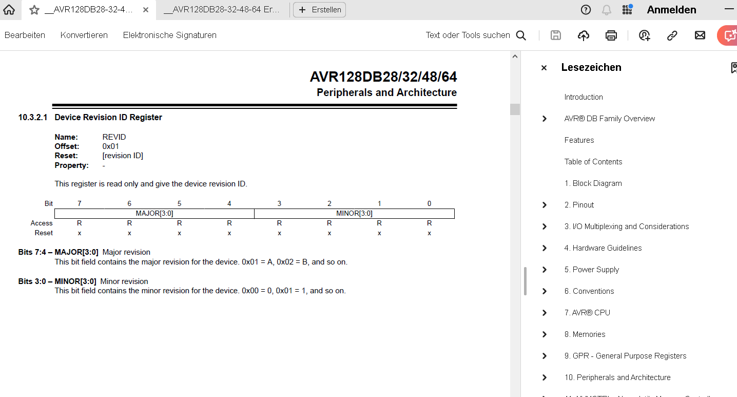
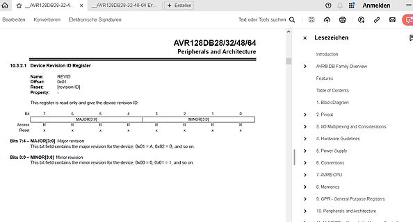
Datenblatt Ausschnitt AVR128DB Device Revision ID Register
AVR128DB28/32/48/64 Peripherals and Architecture 10.3.2.1 Device Revision ID Register Name: REVID Offset: 0x01 Reset: [revision ID] Property: This register is read only and give the device revision ID.
in „AVR128DA64 TCA1 funktioniert nicht mit alternativen Output?“ · Mikrocontroller und Digitale Elektronik · · Screenshots
-
PDF
catalog-3.pdf
Category]: Memory [Desc]: Flash Serial (SPI, Dual SPI) 1.8V 2M-bit 256K x 8 8ns 8-Pin WSON EP MPN: AT45DB642D-CNU [ID]: 000096 [Price]: undef/offer [QTY]: 10 [Category]: Memory [Desc]: Flash Mem Parallel/Serial-SPI 3.3V 64M-Bit 8M x 8 6ns 8-Pin CASON MPN: AT45DB642D-CU [ID]: 000097 [Price]: undef/offer [
-
Datei
main.c
SCL_CLOCK 100 #define F_CPU 8000000 #include<5x8_vertikal_LSB_1.h> #include<util/delay.h> #include<avr/io.h> #include<i2cmaster.h> void write_string_to_OLED_buffer(unsigned char*, char*); unsigned char print_buffer_to_OLED(unsigned char*); unsigned char initialize_OLED(void); int main (void) { unsigned
in „Pointer an Funktion übergeben AVR C“ · Mikrocontroller und Digitale Elektronik ·
-
Datei
tft_data.c
0x79, 0x23, 0x00, 0x6D, 0xF9, 0xF0, 0xD8, 0x89, 0xFE, 0x3C, 0x82, 0x29, 0x60, 0x26, 0x33, 0x05, 0x64, 0xA3, 0x3C, 0x4D, 0xDA, 0x28, 0xD7, 0xDB, 0x2A, 0x6C, 0x9C, 0x18, 0x94, 0x93, 0xB4, 0x2E, 0x8E, 0x2E, 0x8E, 0xFA, 0x21, 0x7B, 0x6D, 0x8B, 0xE4, 0x27, 0xE5, 0x87, 0xA5, 0xDB, 0xC4, 0x5B, 0xC5, 0x7B,
-
Datei
lcdcon_ft245_4bit.asm
231 , 231 , 60 , 90 , 153 .db 128 , 224 , 248 , 254 , 248 , 224 , 128 , 0 .db 2 , 14 , 62 , 254 , 62 , 14 , 2 , 0 .db 24 , 60 , 126 , 24 , 24 , 126 , 60 , 24 .db 102 , 102 , 102 , 102 , 102 , 0 , 102 , 0 .db 127 , 219 , 219 , 123
in „LCD Controller für 640x480 LCD mit mega8515“ · Projekte & Code ·
-
Datei
lcdconpar.asm
231 , 231 , 60 , 90 , 153 .db 128 , 224 , 248 , 254 , 248 , 224 , 128 , 0 .db 2 , 14 , 62 , 254 , 62 , 14 , 2 , 0 .db 24 , 60 , 126 , 24 , 24 , 126 , 60 , 24 .db 102 , 102 , 102 , 102 , 102 , 0 , 102 , 0 .db 127 , 219 , 219 , 123
in „LCD Controller für 640x480 LCD mit mega8515“ · Projekte & Code ·
-
Datei
lcdconpar.asm
231 , 231 , 60 , 90 , 153 .db 128 , 224 , 248 , 254 , 248 , 224 , 128 , 0 .db 2 , 14 , 62 , 254 , 62 , 14 , 2 , 0 .db 24 , 60 , 126 , 24 , 24 , 126 , 60 , 24 .db 102 , 102 , 102 , 102 , 102 , 0 , 102 , 0 .db 127 , 219 , 219 , 123
in „LCD Controller für 640x480 LCD mit mega8515“ · Projekte & Code ·
-
Datei
level1test.asm
============== ; ; start: ; ; Init ; ldi r18, low(RAMEND) out CPU_SPL, r18 ldi r18, high(RAMEND) ; AVR128DA does this during RESET out CPU_SPH, r18 ; ; Set CPU Clock Frequency ; ldi r18, CPU_CCP_IOREG_gc sts CPU_CCP, r18 ldi r18, F_CLK sts CLKCTRL_OSCHFCTRLA, r18 ; ; Constants ; clr zero ;===========
in „AVR Level1 Interrupt“ · Mikrocontroller und Digitale Elektronik ·
-
Datei
8080int-jmp.asm
... .equ ZFL_S = 7 .equ ZFL_Z = 6 .equ ZFL_H = 4 .equ ZFL_P = 2 .equ ZFL_N = 1 .equ ZFL_C = 0 .equ AVR_T = SREG_T .equ AVR_H = SREG_H .equ AVR_S = SREG_S .equ AVR_V = SREG_V .equ AVR_N = SREG_N .equ AVR_Z = SREG_Z .equ AVR_C = SREG_C ;------------------------------------------------; ; Load table value
in „CP/M auf ATmega88“ · Mikrocontroller und Digitale Elektronik ·
-
Datei
BlinkingLED.txt
r24, 0x01 ; 1 644: 2a 85 ldd r18, Y+10 ; 0x0a 646: 9a 89 ldd r25, Y+18 ; 0x12 648: 29 17 cp r18, r25 64a: 09 f4 brne .+2 ; 0x64e <__mulsf3+0x62> 64c: 80 e0 ldi r24, 0x00 ; 0 64e: 8a 87 std Y+10, r24 ; 0x0a 650: ce 01 movw r24, r28 652: 09 96 adiw r24, 0x09 ; 9 654: bc c0 rjmp .+376 ; 0x7ce <__mulsf3+0x1e2
in „AvrStudio 5 Programm zu groß für Attiny 13“ · Mikrocontroller und Digitale Elektronik ·
-
PDF
Umsetzung_und_Implementierung_einer_FFT_f_r_8.pdf
Gewichtsfaktor rcall mpy8s ;8*8Bit = 16Bit - Routine ldi counter1,7 rescale_fensterung: ;rescale(I*x*128)/128 --> 7x ;shieben rechts lsr m8sH ror m8sL dec counter1 brne rescale_fensterung st X+,m8sL ;save Samplewert dec counter2 ;Alle Samples durchlaufen? brne loop_fensterung Hamming_Window: .db 10,15,29,51,75,98,116,126,126,116,98,75,51,29,15,10 Rectangle_Window: .db 128,128,128,128,128,128,128,128,128,128,128,128,128,128,128,128 Alexander Liebhold 13 15.02.2008 Umsetzung und Implementation einer FFT für 8-Bit Mikrocontroller 2.3 Bit-Reversal-Sort Die nächste Aufgabe
in „FFT Tutorial für AVR“ · Mikrocontroller und Digitale Elektronik ·
-
PDF
beginner_de.pdf
SRAM-Daten langsamer zu verarbeiten sind als Da- ten in Registern. Dafür besitzt schon der zweitkleinste AVR immerhin 128 Bytes an SRAM-Speicher. Da passt schon einiges mehr rein als in 32 popelige Register. Die größeren AVR ab AT90S8515 aufwärts bieten neben den eingebauten 512 Bytes zusätzlich die Möglichkeit
in „Langzeittimer für Anfänger“ · Mikrocontroller und Digitale Elektronik ·
-
PDF
AVR_beginner_de.pdf
SRAM-Daten langsamer zu verarbeiten sind als Da- ten in Registern. Dafür besitzt schon der zweitkleinste AVR immerhin 128 Bytes an SRAM-Speicher. Da passt schon einiges mehr rein als in 32 popelige Register. Die größeren AVR ab AT90S8515 aufwärts bieten neben den eingebauten 512 Bytes zusätzlich die Möglichkeit
in „Anfang, aber wie?“ · Mikrocontroller und Digitale Elektronik ·
-
PDF
beginner_de.pdf
SRAM-Daten langsamer zu verarbeiten sind als Da- ten in Registern. Dafür besitzt schon der zweitkleinste AVR immerhin 128 Bytes an SRAM-Speicher. Da passt schon einiges mehr rein als in 32 popelige Register. Die größeren AVR ab AT90S8515 aufwärts bieten neben den eingebauten 512 Bytes zusätzlich die Möglichkeit
in „kommentierter Befehlssatz in deutsch ATmega16“ · Mikrocontroller und Digitale Elektronik ·
-
PDF
beginner_de.pdf
SRAM-Daten langsamer zu verarbeiten sind als Da- ten in Registern. Dafür besitzt schon der zweitkleinste AVR immerhin 128 Bytes an SRAM-Speicher. Da passt schon einiges mehr rein als in 32 popelige Register. Die größeren AVR ab AT90S8515 aufwärts bieten neben den eingebauten 512 Bytes zusätzlich die Möglichkeit
in „Spannungsveränderung schaltet Relais für ca. 30Sek->nur wi“ · Analoge Elektronik und Schaltungstechnik ·
-
PDF
doc7627.pdf
data-flash and temperature sensor. Figure 1-1 . AT90USBKey AT90USBKey Hardware User Guide 1-3 7627A–AVR–04/06 Introduction 1.2 AT90USBKey Features The AT90USBKey provides the following features: ■ AT90USB QFN64 ■ AVR Studio® software interface (1) ■ USB software interface for Device Firmware Upgrade (
in „Problem mit dem TC4469“ · Mikrocontroller und Digitale Elektronik ·
-
Datei
tvtext_v2.asm
,'0'+YSize-YSize/10*10 st Y+, temp ldi temp,0 st Y+, temp rcall print .db "AVR Videogenerator",0 ldi temp,0 st Y+, temp rcall print .db "www.mikrocontroller.net",0 ldi temp,0 st Y+, temp ldi temp,'>' st Y+, temp ldi temp,0 st Y+, temp ldi temp,'>' st Y+, temp st Y+, temp ldi
in „AVR Videogenerator, 40x25 Zeichen, nur 60% CPU Auslastung !“ · Projekte & Code ·
-
Datei
ssd1306.c
-> 14.04.2018 09:13:07 * Description -> Treiber unterstützt das I2C Protokoll. * * * */ #include <avr/io.h> #include <avr/interrupt.h> #include <string.h> #include <stdlib.h> #include "I2C.h" #include "ssd1306.h" static uint8_t DisplayRam[ ( SSD1306_LCD_Width * SSD1306_LCD_HEIGHT ) / 8 ] = "0xFF"; static
in „SSD1306/1309 Library zum Darstellen von Text auf OLED Displays“ · Projekte & Code ·
-
Datei
lcdcon_ft245.asm
231 , 231 , 60 , 90 , 153 .db 128 , 224 , 248 , 254 , 248 , 224 , 128 , 0 .db 2 , 14 , 62 , 254 , 62 , 14 , 2 , 0 .db 24 , 60 , 126 , 24 , 24 , 126 , 60 , 24 .db 102 , 102 , 102 , 102 , 102 , 0 , 102 , 0 .db 127 , 219 , 219 , 123
in „LCD Controller für 640x480 LCD mit mega8515“ · Projekte & Code ·
-
Datei
lcdcon_ft245.asm
231 , 231 , 60 , 90 , 153 .db 128 , 224 , 248 , 254 , 248 , 224 , 128 , 0 .db 2 , 14 , 62 , 254 , 62 , 14 , 2 , 0 .db 24 , 60 , 126 , 24 , 24 , 126 , 60 , 24 .db 102 , 102 , 102 , 102 , 102 , 0 , 102 , 0 .db 127 , 219 , 219 , 123
in „LCD Controller für 640x480 LCD mit mega8515“ · Projekte & Code ·
-
Datei
Kleines_LCD_Tutorial.htm
DB6 DB5 DB4 DB3 DB2 DB1 DB0 L L L L L L H X = "Cursor Home" DB1 = high => Coursor an Anfangsposition (ca. 1,7 Millisekunden) ----------------------------------------------------------------- DB7 DB6 DB5 DB4 DB3 DB2 DB1 DB0 L L L L L H X X = "Entry Mode Set" DB2 = high => Entry Mode Set (ca. 50 Mikrosekunden) ----------------------------------------------------------------- DB7 DB6 DB5 DB4 DB3 DB2 DB1 DB0
in „AVR-Tutorial: LCD - Erweiterung lcd-routines.asm - Bitte um Feedback“ · Mikrocontroller und Digitale Elektronik ·
-
Datei
bootload.lst
) 35 36 37 /* 38 Atmel's AVR assembler is case insensitive, gcc is not. 39 mangled_case.h covers the cases where the representations in the 40 program mix case. 41 */ 42 #include "mangled_case.h" 1 /* 43 44 /* 45 This includes
in „Peter Danneggers Bootloader (fastboot) für AVR-GCC-Toolchain“ · Projekte & Code ·
-
Datei
8080int-jmp.asm
... .equ ZFL_S = 7 .equ ZFL_Z = 6 .equ ZFL_H = 4 .equ ZFL_P = 2 .equ ZFL_N = 1 .equ ZFL_C = 0 .equ AVR_T = SREG_T .equ AVR_H = SREG_H .equ AVR_S = SREG_S .equ AVR_V = SREG_V .equ AVR_N = SREG_N .equ AVR_Z = SREG_Z .equ AVR_C = SREG_C ; TODO: check Z80 flag settings ;----------------------------------
in „CP/M auf ATmega88“ · Mikrocontroller und Digitale Elektronik ·
-
Datei
Schrittmotor.asm
OVF ;0x0044 ; Timer3 Overflow ; reti ;rjmp Posit -Test- ;Zurueck: .ORG 0x0100 ; Adresse 0x200 MTab: .db 0,2,3,5,6,8,9,11,13,14,16,17,19,20,22,24,25,27,28,30,31,33,34,36,38,39,41,42,44,45,47,48 .db 50,51,53,55,56,58,59,61,62,64,65,67,68,70,71,73,74,76,77,79,80,82,83,85,86,88,89,91,92,94,95,96 .db 98,99,101,102,104,105,107,108,109,111,112,114,115,116,118,119,121,122,123,125,126,128,129,130,132,133,134,136,137,138,140,141
in „Spielerei mit einem 2- und 5-Phasen-Schrittmotor“ · Projekte & Code ·
-
Datei
kb.c
/* this keyboard interface is based on avr appnote 313 changes are made for using avr-gcc and atmega8 processors beck@informatik.htw-dresden.de */ #include <device.h> /* ***********************************************************************
in „PS/2 Keyboard am PSoC 3/4/5“ · Mikrocontroller und Digitale Elektronik ·