-
PDF
avr-libc-user-manual-1.8.0.pdf
_MAX UINT32_MAX • #define INT_FAST64_MAX INT64_MAX • #define INT_FAST64_MIN INT64_MIN • #define UINT_FAST64_MAX UINT64_MAX Limits of integer types capable of holding object pointers • #define INTPTR_MAX INT16_MAX • #define INTPTR_MIN INT16_MIN • #define UINTPTR_MAX UINT16_MAX Limits of greatest-width integer types • #define INTMAX_MAX INT64_MAX • #define INTMAX_MIN INT64_MIN • #define UINTMAX_MAX UINT64_MAX Limits
in „Interrupt Probleme beim Arduino“ · Mikrocontroller und Digitale Elektronik ·
-
PDF
Brauchbar_QC12864B.pdf
driving voltage. 2. MECHANICALSPECIFICATIONS ITEM SPECIFICATIONS UNIT Module Size 93.0L×70.0W×13.0(max)H mm View Area 72.0×40.0 mm EffectiveArea 128×64 dots Dot Size 0.48×0.48 mm Dot Pitch 0.52×0.52 mm 深 圳 市 亚 斌 电 子 有 限 公 司 SHENZHEN YABIN ELECTRONICS CO.,LTD ------------------------------------------
-
PDF
ALTES01075-1.pdf
EPX880 & EPX8160: I = 12 mA DC, V = min., 0.2 V OL CCO current Note (4) I Input leakage current V = max., GND < V < V , Note (5) –10 10 A I CCO IN CCO OZ Output leakage current EPX880 & EPX8160: V CCO = max., OUT = VCCO –50 50 A EPX880 & EPX8160: V CCO = max., OUT = GND –100 100 A SC Output short circuit
in „Prüfen von Chips“ · Mikrocontroller und Digitale Elektronik ·
-
PDF
MAX3095-MAX3096.pdf
respect to each other.k The MAX3095 receiver propagation delays are trimmed A MAX3095 / to a predetermined value ±8ns, while the MAX3096 MAX3096 5 delays are trimmed to a predetermined value ±10ns. 150Ω 9 128 Receivers on the Bus 0 The standard RS-485 input impedance is 12kΩ (one- B 3 32 unit loads. The MAX3095/MAX3096 present a 1/4-rive 1k X unit-load input impedance (48kΩ), which allows up to A 128 receivers on a bus. Any combination of these RS- 485 receivers with a total of 32 unit loads can be con
in „Hilfe mit RS485-Receiver-Dattenblatt“ · Mikrocontroller und Digitale Elektronik ·
-
PDF
MAX3095-MAX3096.pdf
respect to each other.k The MAX3095 receiver propagation delays are trimmed A MAX3095 / to a predetermined value ±8ns, while the MAX3096 MAX3096 5 delays are trimmed to a predetermined value ±10ns. 150Ω 9 128 Receivers on the Bus 0 The standard RS-485 input impedance is 12kΩ (one- B 3 32 unit loads. The MAX3095/MAX3096 present a 1/4-rive 1k X unit-load input impedance (48kΩ), which allows up to A 128 receivers on a bus. Any combination of these RS- 485 receivers with a total of 32 unit loads can be con
in „SPI mit RS485-Übertragung: Problem mit zu langen Propagation-Delays“ · Mikrocontroller und Digitale Elektronik ·
-
PDF
mb506-1.pdf
Q D Q D Q D Q D Q Output SW SW Buffer C Q C Q C Q C Q C Q OUT SW1 SW2 Divide Ratio H H 1/64 L H 1/128 H L 1/128 L L 1/256 Note: H = CC, L = open Figure 1. MB506 Block Diagram PIN DESCRIPTION Pin Number Symbol Function 1 IN Input 2 V Power Supply Voltage CC 3 SW1 Divide Ratio Control Input Selecting
in „Eingangsbeschaltung GHz-Vorteiler aus altem Sat-Tuner“ · HF, Funk und Felder ·
-
Datei
MSD.txt
bNumInterfaces : 0x01 (1) bConfigurationValue: 0x01 (1) iConfiguration : 0x00 (0) bmAttributes : 0x80 (128) MaxPower : 0x32 (50) 3 in down n/a 0.002 GET_DESCRIPTOR_FROM_DEVICE URB Header (length: 80) SequenceNumber: 3 Function: 000b (GET_DESCRIPTOR_FROM_DEVICE) 3 in up n/a 0.003 CONTROL_TRANSFER 09 02 20
-
Datei
rpn_boris_A328_v1.7.bas
== Function Convert(incode As Byte) As Byte Local Komma As Byte Komma = 0 Convert = 0 If Incode >= 128 Then Komma = 1 Incode = Incode - 128 End If Select Case Incode Case 0 ' Convert = 126 Convert = 29 Case 1 Convert = 48 Case 2 Convert = 109 Case 3 Convert = 121 Case 4 Convert = 51 Case 5 Convert =
in „Noch ein Taschenrechner auf ATMega Basis“ · Projekte & Code ·
-
PDF
MAX1487-MAX491.pdf
a logic-high output if the input is open circuit.Operate from a Single 5V Supply X Allows up to 128 Transceivers on the Bus 4 The MAX487 and MAX1487 feature quarter-unit-load 8 receiver input impedance, allowing up to 128 MAX487/ (MAX487/MAX1487) cations are obtained using the MAX488–MAX491, whilei
in „SPI Recihweite über RS422 (MAX490) erhöhen?“ · Mikrocontroller und Digitale Elektronik ·
-
PDF
MAX491.pdf
a logic-high output if the input is open circuit.Operate from a Single 5V Supply X Allows up to 128 Transceivers on the Bus 4 The MAX487 and MAX1487 feature quarter-unit-load 8 receiver input impedance, allowing up to 128 MAX487/ (MAX487/MAX1487) cations are obtained using the MAX488–MAX491, whilei
in „MAX491 -Defekt??“ · Mikrocontroller und Digitale Elektronik ·
-
PDF
MSG12864C-TMC-V_07_03.pdf
for LCD Module 78.0 0.5 2.0 74.0 8.0 62.0(VA) 1 CS1 10.85 56.3(AA) 2 CS2 13.0 P2.54*19=48.26 4 4 H1Max 1.8 20- 1.0PTH . . H2 3 GND 20- 2.0PAD 2 2 4 VDD 7 . 1 . 5 VLC 1 . 1 20 2 1 6 D/I 4- 1.0PTH 7 R/W 8 E ) ) A 9 DB0 0 A A 2 5 ( 8 128X64Dots . 4 . 10 DB1 0 5 4 3. 5 1 6 11 DB2 7 3 K 12 DB3 2.25 13 DB4
in „GLCD: Bedeutung von Chip Select“ · Mikrocontroller und Digitale Elektronik ·
-
PDF
MSG12864C-TMC-V_07_03.pdf
for LCD Module 78.0 0.5 2.0 74.0 8.0 62.0(VA) 1 CS1 10.85 56.3(AA) 2 CS2 13.0 P2.54*19=48.26 4 4 H1Max 1.8 20- 1.0PTH . . H2 3 GND 20- 2.0PAD 2 2 4 VDD 7 . 1 . 5 VLC 1 . 1 20 2 1 6 D/I 4- 1.0PTH 7 R/W 8 E ) ) A 9 DB0 0 A A 2 5 ( 8 128X64Dots . 4 . 10 DB1 0 5 4 3. 5 1 6 11 DB2 7 3 K 12 DB3 2.25 13 DB4
in „Datenblatt zu MSG12864A (128*64) GLCD blau“ · Mikrocontroller und Digitale Elektronik ·
-
PDF
AVR_Uebersichtstabelle.pdf
TQFP 100 ATmega1281 128 4 8192 54 16 1.8-5.5 4 2 9 Yes 1+USART 2 Yes Yes 8 Yes Yes Yes Yes Yes 48 17 Yes MLF 64 TQFP 64 ATmega128RZAV 128 4 8192 54 16 1.8-5.5 4 2 9 Yes 1+USART 2 Yes Yes 8 Yes Yes Yes Yes Yes 48 17 Yes MLF
in „Unterschied der AVR'S“ · Mikrocontroller und Digitale Elektronik ·
-
Datei
sinus.txt
Address3)); end process; -- Output registers process begin wait until rising_edge(CLK); --Von 0 to (maxAccum1)/2 : darstellen sinus im Bereich(0,pi) --Von (maxAccum1)/2 to maxAccum1) : darstellen sinus im Bereich(pi,2pi) --D_out1 <= Result1; if (Sign1='1') then for Amplitude in 0 to 25 loop D_out1 <= std_logic_vector(to_unsigned(127,8)+ unsigned(Result1)*Amplitude/128); end loop; else for Amplitude in 0 to 25 loop D_out1 <= std_logic_vector (to_unsigned(127,8)- unsigned(Result1)*Amplitude/128); end loop; end if; -- Sign2 und Sing3 wird nicht benutzt if (Sign2='1'
in „Amplitude von Sinus ändern in FPGA“ · FPGA, VHDL & Co. ·
-
PDF
Vishay_0_91_inch_OLED_128x32_SSD1306.pdf
OLED-128O032F-LPP3N00000 www.vishay.com Vishay 128 x 32 Graphic OLED FEATURES • Type: graphic • Display format: 128 x 32 dots • Built-in controller: SSD1306BZ • Duty cycle: 1/32 • +3 V power supply • Interface
in „Mit Wire.h über I2C auf LCD-Display 1602 zugreifen“ · Mikrocontroller und Digitale Elektronik ·
-
PDF
Vishay_0_91_inch_OLED_128x32_SSD1306.pdf
OLED-128O032F-LPP3N00000 www.vishay.com Vishay 128 x 32 Graphic OLED FEATURES • Type: graphic • Display format: 128 x 32 dots • Built-in controller: SSD1306BZ • Duty cycle: 1/32 • +3 V power supply • Interface
in „Arduino Bibliothek - Methoden bzw. Funktionen en Detail erklärt - gesucht“ · Mikrocontroller und Digitale Elektronik ·
-
PDF
funkmodul.pdf
100 FM Remote Control Systems Freq Range** Part Number Description Transmitter Type (MHz) (Metres) 128S1-433FR1 FM RC System 1 ch 12/24Vdc Pocket Keyfob 433.92 150 128S3-433FR1 FM RC System 3 ch 12/24Vdc Pocket Keyfob 433.92 150 10208S1-433FR1 FM RC System 1 ch 12/24Vdc Handheld 433.92 200 10208S4-433FR1
in „led dimmerschaltung“ · Mikrocontroller und Digitale Elektronik ·
-
PDF
dimmer6.pdf
Mode DMX Funktion Kanal Wert Dimmer 0-255 Ausgang 1: Intensität 0 – 100% 1 0-127 Ausgang 1 aus Switch 128-255 Ausgang 1 ein Dimmer 0-255 Ausgang 2: Intensität 0 – 100% 2 0-127 Ausgang 2 aus Switch 128-255 Ausgang 2 ein Dimmer 0-255 Ausgang 3: Intensität 0 – 100% 3 0-127 Ausgang 3 aus Switch 128-255 Ausgang 3 ein Dimmer 0-255 Ausgang 4: Intensität 0 – 100% 4 0-127 Ausgang 4 aus Switch 128-255 Ausgang 4 ein Dimmer 0-255 Ausgang 5: Intensität 0 – 100% 5 0-127 Ausgang 5 aus Switch 128-255 Ausgang 5 ein Dimmer 0-255 Ausgang 5: Intensität 0 – 100% 6 0-127 Ausgang 5 aus Switch 128-255 Ausgang
in „12V Halogenlampen dimmen“ · Mikrocontroller und Digitale Elektronik ·
-
PDF
AN0177V3-MGRT_MX25L12836E_45E_35E_to_35F.pdf
Part no. MX25L12836E MX25L12845E MX25L12835E MX25L12835F Technology 110nm 110nm 110nm 75nm Density 128Mb 128Mb 128Mb 128Mb VCC 2.7V-3.6V 2.7V-3.6V 2.7V-3.6V 2.7V-3.6V Structure Normal Read 50MHz 50MHz 50MHz 50MHz Maximum Command Clock 133MHz Frequency (except READ, 104MHz 104MHz 104MHz (all commands
in „FLASH Memory Chip im Lenovo X200 von 8 MB auf 16 MB vergroessern“ · PC Hard- und Software ·
-
PDF
DOGM128E.pdf
Issue 10.2014 DOGM GRAPHIC SERIES 128x64, 3.3V ! lo qaniy uned valalein EDb./. m a .mmwit L flt:5 EA DOGM128B-6 + EA LED55x46-WEA LED55x46-W + EA DOGM128W-6 + EA LED55x46-A TECHNICAL DATA * HIGH-CONTRAST LCD SUPERTWIST DISPLAY (STN AND
-
PDF
6_180.pdf
Operating Temp. 0°C - 70°C 0°C - 70°C Performance Specifications MLC SLC Sequential Read Rate 150 MB/sec (max) Sequential Read Rate 170 MB/sec (max) Sequential Write Rate 100 MB/sec (max) Sequential Write Rate 130 MB/sec (max) Ordering Information MLC SLC 32GB FPM32GLSE 16GB FPD16GLSE 64GB FPM64GLSE 32GB FPD32GLSE 128GB FPM28GLSE © 2008 Super Talent Technology. Specifications subject to change without notice. p.1 *Usable capacity may be less than specified after formatting. www.supertalent.com
in „Ständige Aktivität der SSD im Netbook“ · PC Hard- und Software ·
-
PDF
MSP430F2xxx_ppt.pdf
Price F2001 1KB 128B WDT+/A2 Comp_A $0.55 F2011 2KB 128B WDT+/A2 Comp_A 0.70 F2002 1KB 128B WDT+/A2 ADC10 9 0.99 F2012 2KB 128B WDT+/A2 ADC10 9 1.15 F2003 1KB 128B WDT+/A2 SD16_A 9 1.49 F2013 2KB 128B WDT+/A2 SD16_A 9
-
PDF
dmf5001.pdf
.98-0048 OPTREX OPTREX CORPORATION Page 1/15 1.General Specifications Operating Temp. : min. 0˚C ~ max. 50˚C Storage Temp. : min. -20˚C ~ max. 60˚C Dot Pixels : 160 (W) × 128 (H) dots Dot Size : 0.54 (W) × 0.54 (H) mm Dot Pitch : 0.58 (W) × 0.58 (H) mm Viewing Area : 101.0 (W) × 82.0 (H) mm Outline Dimensions
in „graphisches LC-Diplay über LTP ansteuern“ · Mikrocontroller und Digitale Elektronik ·
-
PDF
MS5611-01BA03.pdf
PS Long term stability ±1 mbar/yr SENSOR+IN Digital SDI/SDA dig. Interface SDO Temperature Min Typ Max Unit -IN PGA ADC Filter SCLK Range -40 +85 °C Interface IC (PROM) Resolution <0.01 °C SGND 128 bits Accuracy -0.8 +0.8 °C GND Notes: (1) Oversampling Ratio: 256 / 512 / 1024 / 2048 / 4096 (2) With autozero
in „MSP430 Launchpad und MS5611 Sensor“ · Mikrocontroller und Digitale Elektronik ·
-
PDF
LCD_2.pdf
container and clean environment. 3.General Specification Item Dimension Unit Number of Characters 128 x 64 Dots - Module dimension 75.0 x 52.7 x 8.9(MAX) mm View area 60.0 x 32.6 mm Active area 55.0 x 27.48 mm Dot size 0.41 x 0.41 mm Dot pitch 0.44 x 0.44 mm LCD type STN Negative, Transmissive , blue
in „Grafik-LCD-Text“ · Mikrocontroller und Digitale Elektronik ·
-
PDF
CFAG12864BTMIV.pdf
container and clean environment. * 0407,2 $S0.L 1L.,9L54 Item Dimension Unit Number of Characters 128 x 64 Dots Module dimension 75.0 x 52.7 x 8.9(MAX) mm View area 60.0 x 32.6 mm Active area 55.0 x 27.48 mm Dot size 0.41 x 0.41 mm Dot pitch 0.44 x 0.44 mm LCD type STN Negative, Transmissive, blue Duty
in „avr asm LCD Problem“ · Mikrocontroller und Digitale Elektronik ·
-
PDF
2128wichtig.pdf
Technology o A1 C6 SP t t • HIGH DENSITY PROGRAMMABLE LOGIC t A2 D Q N C5 t — 6000 PLD Gates u u — 128 I/O Pins, Eight Dedicated Inputs O A3 D Q G C4 O — 128 Registers P A4 Logic IGLB C3 P — High Speed Global Interconnect l Array D SQ l — Wide Input Gating for Fast Counters, State P A5 C2 P Machines,
-
PDF
MegaBoardV1.4.pdf
Radig Vorwort: Im Internet kursieren zahlreiche Schaltungen und Anleitungen rund um den ATMega 103,128. Nachteile dieser Schaltungen ist meist, daß sie eine Doppelseitige Platine benötigen. Aus diesen Grund habe ich mal diese Schaltung (Board) entwickelt und hoffe das ich einigen Menschen weiter helfen
in „ATMEGA128 funzt nicht“ · Mikrocontroller und Digitale Elektronik ·
-
PDF
MS5611-01BA01.pdf
Meas. MUX CSB Long term stability -1 mbar/yr SENSOR+IN Interface SDI/SDA dig. SDO Temperature Min Typ Max Unit -IN PGA ADC Filter SCLK Range -40 +85 °C Sensor Memory Interface IC 128 bits Resolution <0.01 °C SGND GND Accuracy -0.8 +0.8 °C Notes: (1) Oversampling Ratio: 256 / 512 / 1024 / 2048 / 4096 (2)
in „16 oder 24 bit mit SPI“ · Mikrocontroller und Digitale Elektronik ·
-
PDF
CY7C68013.pdf
Plastic Quad Flatpack (14 × 20 × 1.4 mm) A101.........................................48 Figure 11-4. 128-Lead Thin Plastic Quad Flatpack (14 × 20 × 1.4 mm) A128 ......................................49 Figure 13-1. Cross-section of the Area Underneath the QFN Package ...................................
in „Stereokamera CY7C68013A + 2 mal MT9D131“ · Mikrocontroller und Digitale Elektronik ·
-
PDF
2019-02-22_SCH_ATMega_Eval_DEVEL_v0_2_.PDF
8 1 2 3 4 5 6 7 8 ATMega_Eval A (Block Diagram) A POWER LED ARDUINO HEADER 12/24V IN LEDs B ATmega128 B 23 IO's JTAG ISP Taster/DIP-Schalter USB (UART) OLED 128x64 C C OLED 128x64 Piezo HEADER Drehenkoder (I2C) D D Title ATMega_EvalDEVEL Size Number Revision A3 2 - Block Diagramm 0.2 Date: 22.02.2019
in „AD.wandler und FFT auf Atmega 128A“ · Mikrocontroller und Digitale Elektronik ·
-
PDF
ads1220.pdf
Equation 12, which are given in Equation 13 and Equation 14: V CM (MIN) AVSS + 0.2 V + ½ Gain · IN (MAX) (13) V CM (MAX) AVDD – 0.2 V – ½ Gain · VIN (MAX) (14) In order to calculate the minimum and maximum common-mode voltage limits, the maximum differential input voltage (VIN (MAX) that occurs in the
in „ADS1220 Temperatur SPI“ · Mikrocontroller und Digitale Elektronik ·
-
Datei
Sinus.c
set down-counting (COM0B) TCCR0B = (1<<CS00) | (1<<WGM02); // WGM02 =1 -> Phase Correct PWM aber: Max !=0xff sondern Max = OCR0A // CS - Prescaler auf 8 = Clk / 8 (CS01=1) // CS - Prescaler auf 1 = Clk (CS00=1) // 1 Zyklus (0x00 - 0xff) = 8MHz/256/Prescaler = 31,25kHz/Prescaler OCR0A = 64; // Top //
in „Stabilitätsproblem oder Verständnisproblem bei Timer (PWM) ATmega88“ · Mikrocontroller und Digitale Elektronik ·
-
PDF
SW017_ISO_tag_DS.pdf
serially output the data. The data rate is set to 32 clocks per cycle. § Memory The memory contains 128 bits memory array custom configurable. The in factory electrical coding is done according to a customer list of codes. The bits are read serially in order to control the modulator. The 128 bits output
in „Kontaklose Chipkarten????“ · Mikrocontroller und Digitale Elektronik ·
-
 Bild
Tabelle mit Mikrocontroller-Spezifikationen
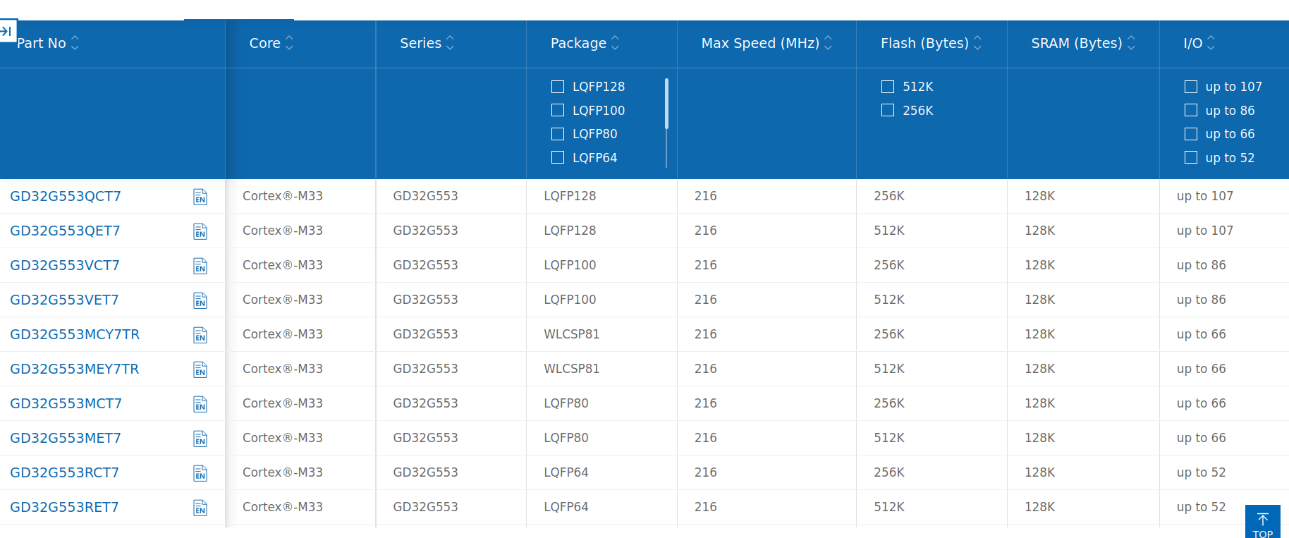
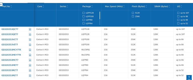
Part No, Core, Series, Package, Max Speed (MHz), Flash (Bytes), SRAM (Bytes), I/O GD32G553QCT7, Cortex-M33, GD32G553, LQFP128, 216, 256K, 128K, up to 107 GD32G553QET7, Cortex-M33, GD32G553, LQFP128, 216, 512K, 128K, up to 107 GD32G553VCT7
in „Linux 6.13 ante portas, neue Funktionen in der Arduino Cloud, Prozessrechner und mehr“ · Mikrocontroller und Digitale Elektronik · · Screenshots
-
Datei
config.txt
prop(SdDisplayBufferMaxWidth)=720 kreatv-app-webkit-portal::prop(SdDisplayBufferMaxHeight)=576 kreatv-app-webkit-portal::prop(RenderingBufferMaxWidth)=1920 kreatv-app-webkit-portal::prop(RenderingBufferMaxHeight)=1080 kreatv-app-webkit-portal
in „Motorola Vip19x0 (Big brother of Vip1710)“ · Mikrocontroller und Digitale Elektronik ·
-
Datei
stoppuhr.c
0; } temp = 0; } TCNT1H=T1_H; TCNT1L=T1_L; } /* timer wert über adc eingang (vom poti) verstellen max wert = 65535 --> sehr schnell ;) min wert = 33789 --> zeit = ?? value = ((value-128) * 15873)/128; skalierung auf max 15873 damit der timer nicht über 65535 geht -128 damit man auch negative werte schaffen
in „timer interrupt problem“ · Mikrocontroller und Digitale Elektronik ·
-
Datei
MainsComp1.c
// PLL values to reach 521/625 cycle #define PLL_MAX 255 #define PLL_MIN 60 #define FIX_CYCLE_TIME 209 // max sine cycle: 210 + 210 + 256 = 676 (50Hz - 8%) // min sine cycle: 210 + 210 + 61 = 481 (60Hz + 8%) ISR( PCINT0_vect ) // zero cross detection
in „PWM synchron zu 50Hz Netz“ · Mikrocontroller und Digitale Elektronik ·
-
PDF
N79A8211.pdf
www.dycmcu.com 经济AD型8位FLASH单片机 N79A8211 Rev. 1.62 内置8通道10bit-A/D转换器8位FLASH单片机 选型指南 内部 2 I/O 型号. 存储器 E PROM MAX ADC PWM RC 精 温度范围 封装 度 N79A8211-D20R 4KB/128B 128B 18 8-10bit 2 2% -40+85℃ DIP-20 N79A8211-S20R 4KB/128B 128B 18 8-10bit 2 2% SOP-20 -40+85℃ N79A8211-D16R 4KB/128B 128B 14 6-10bit 2 2% -40+85℃ DIP-16 N79A8211-D08R 4KB/128B 128B 6 4-10bit 1 2% -40+85℃ DIP-8 N79A8211-D20 4KB/128B 128B 18 8-10bit 2 30% DIP-20 -40+85℃ N79A8211-S20 4KB/128B 128B 18 8-10bit 2 30% -40+85℃ SOP-20 N79A8211-D16 4KB/128B 128B 14 6-10bit 2 30% -
in „Induktionskochfeld hacken / optimieren“ · Haus & Smart Home ·
-
PDF
CY7C64613.pdf
...........................................................................................40 11.3 128 PQFP ...............................................................................................................................41 11.3 128-Lead Plastic Quad Flatpack ...........................
in „Verkaufe CY7C64613-52NC“ · Markt ·
-
PDF
CY7C64613_1.pdf
...........................................................................................40 11.3 128 PQFP ...............................................................................................................................41 11.3 128-Lead Plastic Quad Flatpack ...........................
in „Logikanalzyer mit FT232BL“ · Mikrocontroller und Digitale Elektronik ·
-
Datei
ICP_Drehzahl.c
1 buffer[2]=buffer[2]+128; //128 dazu addieren um dp (Komma) am Display zu aktivieren -> siehe max 7219 Tabelle transmit(0x03,buffer[2]); //Display 2 transmit(0x04,buffer[3]); //Display 3 transmit(0x05,buffer[4]); //Display
in „Frage zu Timereinsatz (Atmega8/Frequenzzähler/Drehgebercode)“ · Mikrocontroller und Digitale Elektronik ·
-
PDF
CS5343-44_F5.pdf
SERIAL AUDIO INTERFACE Logic “0” = GND = 0 V; Logic “1” = VA, CL= 20 pF. Parameter Symbol Min Typ Max Unit Master Mode MCLK Period (Double-Speed, 384x Mode) tclkw 24 - 30 ns (Double-Speed, 192x Mode) 48 - 60 ns (Double-Speed, 256x Mode) 36 - 45 ns (Double-Speed, 128x Mode) 72 - 90 ns (Single-Speed,
in „Genesys 2 (Xilinx Kintex 7): Audio-Codec Implementierung und Filteranbindung“ · FPGA, VHDL & Co. ·
-
PDF
Futaba_VFD_GP1120A01A.pdf
Refer to FIGURE-1) Table-1 Item Specification Unit (W) 130±1 Outer dimensions (H) 38.5±1 mm (T) 22.0 MAX. Weight Approx. 100 g 2-2. SPECIFICATIONS OF THE DISPLAY PANEL Table-2 Item Specification Unit Display Area 83.05(W)×20.65(H) mm Number of Dots 128×32 Dot Dot Size (H×W) 0.5×0.5 mm Dot Pitch (H×W) 0.65
in „V: 2 Stück Futaba VFD Display's, 128x32 Pixel“ · Markt ·
-
PDF
EM4005_DS.pdf
bits are read serially in order to control the modulator. The data rate is set to 32 clocks per bit. 128 bits output sequence is repeated continuously until power goes off. Copyright © 200, EM Microelectronic-Marin SA 4 www.emmicroelectronic.com EM4005 EM4105 Memory Map 128 bit pattern identification ISO
in „Verzweiflung am U2270B“ · Mikrocontroller und Digitale Elektronik ·
-
Datei
rpn_boris_A328_v1.8.bas
== Function Convert(incode As Byte) As Byte Local Komma As Byte Komma = 0 Convert = 0 If Incode >= 128 Then Komma = 1 Incode = Incode - 128 End If Select Case Incode Case 0 ' Convert = 126 Convert = 29 Case 1 Convert = 48 Case 2 Convert = 109 Case 3 Convert = 121 Case 4 Convert = 51 Case 5 Convert =
in „Noch ein Taschenrechner auf ATMega Basis“ · Projekte & Code ·
-
Datei
rpn_boris_A328_v1.9.bas
== Function Convert(incode As Byte) As Byte Local Komma As Byte Komma = 0 Convert = 0 If Incode >= 128 Then Komma = 1 Incode = Incode - 128 End If Select Case Incode Case 0 ' Convert = 126 Convert = 29 Case 1 Convert = 48 Case 2 Convert = 109 Case 3 Convert = 121 Case 4 Convert = 51 Case 5 Convert =
in „Noch ein Taschenrechner auf ATMega Basis“ · Projekte & Code ·
-
Datei
Serial_Plot.txt
= 7 Calibration run 2 Channel 0: ADC average value = 127 Diff = -1 Channel 1: ADC average value = 128 Diff = 0 Channel 2: ADC average value = 128 Diff = 0 Channel 3: ADC average value = 128 Diff = 0 Calibration run 3 Channel 0: ADC average value = 128 Diff = 0 Range 10 calibration complete *********
in „Wittig(welec) DSO W20xxA Open Source Firmware (Teil5)“ · Mikrocontroller und Digitale Elektronik ·
-
PDF
MAX481_422.pdf
a logic-high output if the input is open circuit.r Multiple Transceiver Applications The MAX487 and MAX1487 feature quarter-unit-load MAX3030E–MAX3033E: ±15kV ESD-Protected, 4 receiver input impedance, allowing up to 128 MAX487/ +3.3V, Quad RS-422 Transmitters 8 MAX1487 transceivers on the
in „Problem mit MAX481 Transmitter“ · Mikrocontroller und Digitale Elektronik ·