-
PDF
eeprom_progger_schaltplan.pdf
C21 1 1K U9 PIC16Fxx J8 B U4 2 1 RA2 RA1 18 100nF 1 B U13 8 VCC CS 1 3 2 RA3 RA0 17 R17 1K 2 1 A0 VCC 8 7 PE CLK 2 4 3 RA4/T0CKI OSC1/CLKIN 16 3 2 7 C7 6 3 4 15 C16 3 A1 TEST 6 100nF 5 ORG DI 4 5 5 MCLR OSC2
in „Eeprom-Progger unter XP will keine 24Cxx bearbeiten“ · Mikrocontroller und Digitale Elektronik ·
-
PDF
RF12_code.pdf
: v1.1 Function: Package send Demo Processor PIC16F73 DIP-28 Clock: 10MHz Crystal Operate frequency: 434MHz Data rate: 4.8kbps Package size: 23byte Author: Simon.Yang Company: Hope microelectronic Co.,Ltd
in „Sehr einfache Funkübertragung (8 Bit)“ · Mikrocontroller und Digitale Elektronik ·
-
PDF
91008b.pdf
regulated voltage is cost effective and can be justified. However, there are applications where the PIC12/16/17 is the main controller and low voltage Assuming a line voltage of V 1= 115V and line is not required by other components except the PIC12/ frequency = 60 Hz, 16/17. In these instances, the cost
in „5VDC aus 230VAC“ · Mikrocontroller und Digitale Elektronik ·
-
PDF
ADT7301_-__1_C_Accurate__13_Bit__Digital_Temperature_Sensor__ADT7301.pdf
SCLK nous serial port (SSP) is configured as an SPI master with the clock polarity bit set to a Logic 1. In this mode, the serial clock DOUT MISO line of the PIC16C6x/7x idles high between data transfers. Data DIN MOSI 8 0 is transferred to and from the ADT7301 in two 8-bit serial data CS PC1 8 operations
in „Implementierung eines ADT7301 an einem MSP430FR5729“ · Mikrocontroller und Digitale Elektronik ·
-
PDF
Lora_MainboardOutputJob.PDF
P4 Lora-Chip Address=0xDE CO1 22pF PI1PIC0 P1 CIC2 COY PIC20 PIC28 Y X1 7 X2 32.768kHz PIC20 X2 PIC27 PX0 1 CO2 22pF P1 PIC20 Vbat PIC26 PX0 2 PI2PIC0 5 PIC20 GND PIC25 PX0 3 MCP79411 PX0 4 Real-Time-Clock (RTC) Connector Mainboard/Daughterboard CO DO1 R5 PI50 PI52 PD12 PI11 1K Full_Charged/Green COC IC3 5 XO1 PIIC01 STAT PIC35 PI102 PIIC02 GND PI101 PIIC03 PIC34 VBat Battery Connector MCP73832T-2DCI CO P33 P3 PR6 4.7uF PI14 P4.7uF P2K Connector for
in „Arduino Nano mit RN2483“ · Mikrocontroller und Digitale Elektronik ·
-
Datei
status_txt.TXT
ü#000099 00:00:00 T41 version 1.1 build 116 (GPS Version 4.11.2 ARM (10:56:13 Sep 8 2004)) #000099 00:00:00 PIC version 1.2 #000099 00:00:00 read1: Status1 = 10 Status2 = 9f #000099 00:00:00 read2 Status1 = 0 Status2 = 9f ü ü #000099 00:00:00 T41 version 1.1 build 116 (GPS Version 4.11.2 ARM (10:56:13 Sep 8 2004)) #000099 00:00:00 PIC version 1.2 #000099 00:00:00 read1: Status1 = 11 Status2 = 8f #000099 00:00:00 read2 Status1 = 0 Status2 = 8f ü#000099
in „[S] GSM-Module mit GPRS“ · Markt ·
-
PDF
AES-S6MB-LX9-G_SCH_RevC.PDF
Title: Sheet 4 - FPGA Bank 0 Size: Document Number: Rev: B S6-LX9-SCH-C C Date8/2/2012 Shee4 of10 1 2 3 4 5 6 1 2 3 4 5 6 A A U4B BANK 1 F15 FPGA_PMOD1_P1 +3.3V IO_L01p_1_A25PIF16F15 FPGA_PMOD1_P2 IO_L01n_1_A24_VREF PIC17F16 FPGA_PMOD1_P3 C1 I2 P01 92 IO_L29p_1_A23_M1A13 PIC18C17 FPGA_PMOD1_P4 C87
in „Pulse Generator nicht genau genug, brauche Hilfe“ · FPGA, VHDL & Co. ·
-
Datei
irmpconfig.h
BE INCLUDED BY IRMP.H! * * Copyright (c) 2009-2014 Frank Meyer - frank(at)fli4l.de * Extensions for PIC 12F1820 W.Strobl 2014-07-20 * * $Id: irmpconfig.h,v 1.121 2014/09/15 12:36:28 fm Exp $ * * This program is free software; you can redistribute it and/or modify * it under the terms of the GNU General
in „IRMP-Problem“ · Mikrocontroller und Digitale Elektronik ·
-
PDF
Geiger_PIC18F2550.pdf
radiation measurements. 1 PC board, code 607, available Semiconductors Circuit from the EPE PCB Service, 1 PIC18F2455 or PIC18F2550 The full circuit diagram for the PIC size 98mm × 70mm (see text) preprogrammed Digital Geiger
in „Geiger Counter Sparkfun“ · Mikrocontroller und Digitale Elektronik ·
-
Datei
irmpconfig.h
1 // Samsung + Samsg32 >= 10000 ~300 bytes #define IRMP_SUPPORT_KASEIKYO_PROTOCOL 1 // Kaseikyo >= 10000 ~250 bytes // more protocols, enable here! Enable Remarks F_INTERRUPTS Program Space #define IRMP_SUPPORT_JVC_PROTOCOL
in „IRMP - Infrared Multi Protocol Decoder“ · Projekte & Code ·
-
PDF
PIC.pdf
February 2011 After reading the two quotes above I spent an evening working out the technique on a PIC 18F25K22. I then read the original paper more thoroughly and found the link to Application Note December 2010 November 2010 AN1072 which explains how it works on PICs with a 0.6V or 1.2V reference.
in „Aref Spannung, was ist besser?“ · Mikrocontroller und Digitale Elektronik ·
-
Datei
main.c
include <gtk/gtk.h> #include <windows.h> #include <math.h> #define XMAX 80 #define YMAX 50 #define SZ_PIC_X 8 #define SZ_PIC_Y 16 #define MUL_PIC_X 25 #define MUL_PIC_Y SZ_PIC_Y #define OFF_PIC_X 13 #define OFF_PIC_Y 5 char buffer[XMAX][YMAX]; GtkWidget *window; cairo_surface_t *image; double zoomX=1.28
in „[GTK+] Animation mit Cairo viel zu langsam“ · Softwareentwicklung ·
-
Datei
bauteile_001.txt
30 2,00 50 NE555 SO TI 25 2,00 10 AT89C4051-24PI DIL Atmel 5 2,00 7 SX28AC/DP DIL Ubicom 7 5,00 3 PIC18F4539-I/P DIL Microchip 3 6,00 3 PIC16F88-I/P DIL Microchip 3 3,00 3 PIC16C58B/JW DIL Microchip 3 3,00 2 PIC16C56A/JW DIL Microchip 2 2,00 6 PIC18F242-I/SP DIL Microchip 3 3,00 3 LPC2101F TQFP 3 3,00 9 MSP430F1121A TSSOP TI 9 4,00 5 MSP430F149I LQFP TI 5 9,00 60 29F040C-70 PLCC 60 6,00 1 10 25P10AVG ST 10 3,00 ------------------------------------------------------------------------------------- Alles komplett
in „Verkaufe diverse Bauteile“ · Markt ·
-
Datei
irmpconfig.h
BE INCLUDED BY IRMP.H! * * Copyright (c) 2009-2015 Frank Meyer - frank(at)fli4l.de * Extensions for PIC 12F1820 W.Strobl 2014-07-20 * * $Id: irmpconfig.h,v 1.134 2015/06/15 11:40:54 fm Exp $ * * This program is free software; you can redistribute it and/or modify * it under the terms of the GNU General
in „Umfrage: welche IR-Protokolle nutzt ihr mit IRMP?“ · PC Hard- und Software ·
-
PDF
DDS_ONE.pdf
PA19P 39U P TxX x Y2HC49/4H_SMX A POPPowePOEtXTINT0P I U 1PA05 1 PB06P I U POFLASH_CS# PIC302 PIGND1 I A I P O BT_UP U P13 1PA06 2 PA17P 36U PODDS_IOSYNC 0805 OD D D3.3V PBT_DOWNN P I U 1 0 1 4 PA16P I U 1 0 3 5ESET 18p V V V POBT_CYCPOPA30 P I U 1PA30 5 E PA14P
in „Signalgenerator entworfen - brauche Feedback!“ · Mikrocontroller und Digitale Elektronik ·
-
PDF
LCM2.pdf
14 B0 B1 B2 B3 B4 B5 Vcc 100µH Ccal 1000pF 1 + + ) 4 n u Timer 0 PIC 16F628 Reset o r F - - k o 0 n u 0 k 17 B7 B6 U ( 0 0 1 1 + 5 13 12 15 16 1N914 C "Zero" 10µF X1 33pF 33pF 4MHz Drawn by VK3BHR RY1 5V N/O 1K PIC 1K 16F628 4MHz 1K 0.1µF crystal 1K ZERO P/B 33pF 4.7K / c L i 4.7K 5K 33pF o w T S 100K trimpot + 47K 100K 10µF T + 100K 10µF T + 10uF 0.001µF 0.001µF µ 7805 0 1 22µF RELAY + 25V + - 1N914 Backlight
in „LC-Meter“ · Markt ·
-
PDF
d03000.pdf
DOKUMENTATION PIC18F97J60 HAUPTPLATINE 1. EINLEITUNG Die Hauptplatine des PIC-Lehrsystems ist sehr modern und leistungsfähig. Die einzelnen Ein- und Ausgabepins des Prozessors sind in der energiesparenden 3,3 Volt Technik
in „PIC18F97J60 als Webserver“ · Mikrocontroller und Digitale Elektronik ·
-
PDF
AN040_Sqrt.pdf
value was tested then get bra Done32 ; out bra Squar16 ; elso go back for another test NxtBt16 addlw 0x00 ; clear carry movff RES0, TEMP0 ; copy the last good approximation movff RES1, TEMP1 rrcf BITLOC1, F, a ; rotate the bit location register rrcf BITLOC0
in „Netzspannung auf LCD mit PIC“ · Mikrocontroller und Digitale Elektronik ·
-
PDF
AN040_Sqrt.pdf
value was tested then get bra Done32 ; out bra Squar16 ; elso go back for another test NxtBt16 addlw 0x00 ; clear carry movff RES0, TEMP0 ; copy the last good approximation movff RES1, TEMP1 rrcf BITLOC1, F, a ; rotate the bit location register rrcf BITLOC0
in „Schneller sqrt()-Ersatz ohne FPU“ · Mikrocontroller und Digitale Elektronik ·
-
Datei
tft.c
0x3b3b3bUL); /* light grey */ EVE_cmd_dl(DL_VERTEX_FORMAT); /* set to 0 - reduce precision for VERTEX2F to 1 pixel instead of 1/16 pixel default */ /* draw a rectangle on top */ EVE_cmd_dl(DL_BEGIN | EVE_RECTS); EVE_cmd_dl(LINE_WIDTH(1U * 16U)); /* size is in 1/16 pixel */ EVE_color_rgb(BLUE_1); EVE_cmd_dl
-
PDF
On_Chip_Debug_Spec_51242a.pdf
2. PIC16F87X Debugger Control 2.1 Introduction .......................................................................................... 7 2.2 Highlights ..................................................
in „PIC12F509 hidden features und "High Flash"“ · Mikrocontroller und Digitale Elektronik ·
-
PDF
Hauptplatine.pdf
PI30010 PORX PIP1504 PIP12011 PIU109 RESET AVCC PI32030 C0 Display PIP12022 PIC401 PIC402 AREF PIU103210 C1010 Q3 Summer Cap P12 PIU1012 PIU1031 C133 C2 Cap GND PIQ102 Q1Q1 C 22pF Y1Y PIU1013XTAL2 GND PIU101112 Cap 100nF BC547 C C5C 1 16MHz XTAL1 GND 100nF PIC501 PIC5020 VCC VCC Q0 ATmega16-16PC GND Cap 22pF 02 R2 GND R6R6 R5R5 Res2 Res2 P1616 P181 01K7 R14K7 PIP16011 Pin 1 PIP18011 2 PIP1802 Pin 99 PIP16022 GND Pin 3 PIP18033 4 PIP1804 Pin 11 PIP16033 Pin 4 PIP18055 6 PIP1806 Pin 12 Temp1
in „AVR Wecker mit Netzwerk“ · Mikrocontroller und Digitale Elektronik ·
-
PDF
Hauptplatine.pdf
PI30010 RX PIP1504 PIP12011 PIU109 RESET AVCC PI32030 C0 Display PIP12022 PIC401 PIC402 AREF PIU103210 C1010 Summer Cap P12 PIU1012 PIU1031 C133 C2 Cap GND Q0 C 22pF Y1Y PIU1013XTAL2 GND PIU101112 Cap 100nF PIQ102 Q1Q1 C C5C 1 16MHz XTAL1 GND 100nF BC547B PIC501 PIC5020 VCC VCC ATmega16-16PC GND Q3 Cap P1919 22pF 02 R2 PORX PIP1901 R6R6 R5R5 PIP1902 Res2 Res2 P1616 POTX PIP1903 GND P181 01K7 R14K7 PIP16011 Pin 1 PIP18011 2 PIP1802 Pin 99 PIP16022 RS232 GND Pin 3 PIP18033 4 PIP1804 Pin
in „AVR Wecker mit Netzwerk“ · Mikrocontroller und Digitale Elektronik ·
-
Datei
frq_intrc.asm
******* ; Das Programm beginnt mit der Initialisierung Init ; Komperatoreingange (default ein) des PIC16F628a ausschalten MOVLW B'00000111' ; alle Comparatoreingaenge aus MOVWF 0X1f ; bei PIC16F62X bsf STATUS, RP0 ; Bank 1 movlw Ini_opt ; pull-up on movwf OPTION_REG movlw B'11111000' ; RA0 .. RA2 outputs
in „Frequenzzähler 1Hz-100khZ“ · Mikrocontroller und Digitale Elektronik ·
-
PDF
191142-03.pdf
Signale Brückengleichrichters B4 geschaltet, des- Widerstand R6 und der Kondensator C4 des Encoders ENC1A sowie dessen Tas- sen Wechselspannungsanschlüsse mit erfüllen die gleiche Aufgabe an der Netz- ters ENC1B (Auswahl der Motor-Drehrich- VCC R12 R7 R6 R5 R2 R1 R9 IC2 0 k k k k k k PIC18F45K22-E/P 1 4
in „Einstellbarer 1-kW-AC-Motortreiber“ · Mikrocontroller und Digitale Elektronik ·
-
Datei
HD44780.INC
; This file is succesful tested with ; PIC16F1827, PIC16F628/-A, PIC16F876/-77 ; PIC16F84 , ; LCD-Timing: Timing in LCD_Init is fine up to fosc 10MHz ; fosc >10MHz needs an other Sub "Delay1ms" for ; fosc in use ;****************************
in „Warum, geht die zweite Displayzeile nicht? PIC Assembler“ · Mikrocontroller und Digitale Elektronik ·
-
PDF
MapCom.pdf
PIC101 VPIC202 PIC201 NLTXA V+ PIU100V+ C1- PIU10024 OC3 COC PIU110DSRA TXA PIU1101NLRXA C2+ PI2100C2- C1+10C3 C1-0 V-V0 4 PI4110DTRA RXA PIU11077XA A U_TX_MISO 9 C2- PI14 TX_MX0M PIC302 PIC301 PIC402 PIC401
in „[V] Weiterer M8, GPS, GSM Siemens M20, ATmega128“ · Markt ·
-
PDF
Elektronische_Waage_PIC18F4520.pdf
Elektrische Waage Projektieren & Entwickeln Die Zuger Techniker- und Informatikschule Familien Zwei PIC-Familien eignen sich besonders für Bastler. • Die etwas älteren 14-Bit-Kern-PICs haben Bezeichnungen, die mit "PIC16F..." beginnen. Im Web findet man jede Menge fertiger Schaltungen mit diesen Typen
in „Elektronische Waage“ · Analoge Elektronik und Schaltungstechnik ·
-
PDF
MB1075.pdf
PIR5601PIR5602 PIC2001 PIC2002 PA7 PIU5043 PA7 PD7 PIU50123 PD7 PA6A G2G PG5 BA1 P BA1 A 1 SB1919 X2 20pF PPPE[0..15] PE[ ..15] PA8 P I U 5 PA8 0 0 PD8 P I U 5 0 7 7 PG101 G3G PG8G SDCLKLK POSDCLK COX3 PA9A PIU50101PA9
in „.net auf STM32F429ZI“ · Mikrocontroller und Digitale Elektronik ·
-
PDF
HORIBA_Schreibtisch_Rev1.2.pdf
RB7/T1OSI/PGD 13 A2- B 5 VSS ULN2003AD BU6 Frequenz Rechteck GND PIC16F628SO +15V VR2 2 4 5 RETS-0915 S O TVR07--390 1 3 X1-1 1 V+ A1+ D1 D2 K3 6 G red "AB" P 8 P600-H P600-H A2- DIN8POLR D3 D4 black P600-H
in „Höhenversllbarer Schreibtisch“ · Mikrocontroller und Digitale Elektronik ·
-
PDF
Nixe_Uhr_Oben__2.pdf
JP1 1 2 3 4 5 6 7 8 9 10 11 12 13 14 15 16 4 4 4 4 4 4 4 4 4 4 4 4 4 4 4 4 4 17 1 D 1D 1 D 1 D 1 D 1 D 1D 1 D 1 D 1 D 1 D 1D 1 D 1 D 1 D 1 D 1D V V V V V V V V V V V V V V V V V 18 IC11PIC17IPC16IPC15IPC14IPC13IPC12IPC10IPC9PIC8PIC2PIC3PIC4PIC5PIC6PIC7PIC1P
in „Nixie Uhr Probleme :-(“ · Analoge Elektronik und Schaltungstechnik ·
-
PDF
Nixe_Uhr_Oben__2.pdf
JP1 1 2 3 4 5 6 7 8 9 10 11 12 13 14 15 16 4 4 4 4 4 4 4 4 4 4 4 4 4 4 4 4 4 17 1 D 1D 1 D 1 D 1 D 1 D 1D 1 D 1 D 1 D 1 D 1D 1 D 1 D 1 D 1 D 1D V V V V V V V V V V V V V V V V V 18 IC11PIC17IPC16IPC15IPC14IPC13IPC12IPC10IPC9PIC8PIC2PIC3PIC4PIC5PIC6PIC7PIC1P
in „Zeigt her eure Kunstwerke (2017-2019)“ · Projekte & Code ·
-
Datei
WAspic.pas
or not running; EnableWindow(suchbtn,false); end else begin sprint('WAspic '+AsVersion+' Assembler f r MicroChip PIC-Controller (12+14 Bit Core)'#13); for i:= 1 to ParamCount do begin N:= ParamStr(i); if pos('-L',N)<>0 then begin AList:= true; N:= ''; end; end; end; Ex:= ''; i:= length(N); if pos('.
-
Datei
16F872.H
// HEADER FILE #if !defined ICD_DEBUG && !defined ICD2_DEBUG #pragma chip PIC16F872, core 14, code 2048, ram 32 : 0xBF /0 /3 #elif defined ICD2_DEBUG #pragma chip PIC16F872, core 14, code 0x700, ram 32 : 0xBF /0 /3 // last 256 locations are reserved for debugging //RESERVED RAM LOCATIONS char ICD2R1 @ 0x70; char reservedICD2[11] @ 0xB5; // reserved RAM for ICD2 #pragma stackLevels 7 // reserve one level for debugging #else /* ICD_DEBUG */ #pragma chip PIC16F872, core 14, code 0x700, ram 32 : 0xBF
in „Probleme beim Compilieren von .c zu .hex“ · Mikrocontroller und Digitale Elektronik ·
-
Datei
RFM70.h
******************************************* copyright(c) 2010 Title: RFM70 simple example based on PIC c Current version: v1.0 Function: RFM70 demo processor: PIC16F690 Clock: 8M Crystal Author: baiguang(ISA) Company: Hope microelectronic Co.,Ltd. Contact: +86-0755-82973805-846 E-MAIL: rfeng@hoperf.com
in „Hat jemand Erfahrung mit dem 2,4GHz-Transceiver RFM70?“ · HF, Funk und Felder ·
-
PDF
AS-I_DMX.pdf
ISP I F V1 ASIP DSR ATMEL Pinout I P1 V8V PST P I V 2 0 2 1 X1X A 39V 1W 0 1 PIX101 P2 P I V 2 ASIN U5RD P I V 2 0 2 3 R2R2 2 PIX102 22kmax. 30mA FID P I V 2 0 5 01 +24V Header 2 C2C R1R max. 4mA G PIC201 PIC20PPIRP10I1VCAP0
in „AS-i AktorSensor - Interface IC's“ · Haus & Smart Home ·
-
Datei
memory.c
Name memory.c @Summary This is the generated driver implementation file for the MEMORY driver using PIC10 / PIC12 / PIC16 / PIC18 MCUs @Description This file provides implementations of driver APIs for MEMORY. Generation Information : Product Revision : PIC10 / PIC12 / PIC16 / PIC18 MCUs - 1.81.7 Device
in „MPLAB X IDE Frage C code Programmierung“ · Mikrocontroller und Digitale Elektronik ·
-
PDF
70687A-1.pdf
C6, C9, 0.1 uF Capacitor, Ceramic, 16V, +/-10%, X7R, Murata Electronics North America GRM188R71C104KA0 C10, C12, C13 SMT 0603 1D 3 C7, C8, C11 1 uF Capacitor, Ceramic, 6.3V, +/-10%, X5R, Murata Electronics North
in „Was darf man von einer PCB-Antenne erwarten?“ · HF, Funk und Felder ·
-
PDF
gh_usb_rev_a1.pdf
PIC7PIC701 ND P I U 2 D44 T H_H_OC1_N PIU2054 P2 P0 COR422R PIJ104GND PIJ106 100nF NLD P I U 2 D55 O H_DM1 P I U 2 0 5 0 C2 I2 PIR502PIR501 NLD P I U 2 D66 H H_DP1 P I U 2 0 5 1 C8C8 C9C9 440068-1 1M COU1
in „Grasshopper und USB-Host“ · Mikrocontroller und Digitale Elektronik ·
-
Datei
HD44780.INC
HD44780-LCDs ; Succesful tested with ; PIC16F1827, PIC16F628/-A, PIC16F876/-77, PIC16F84 ; Timing: For the LCD ist timing fine up to fosc 32MHz. For exact ; timing in delays use the multiplicator "FOSC_MULT" ; e.g.: movlw .10*FOSC_MULT ; CALL
in „was genau ist eine library“ · Mikrocontroller und Digitale Elektronik ·
-
Datei
1wire.c
von a)--> b)-->a)fM und wieder zurück a)fM--> b)--> a). 3) 'sStp' (8 bit Datenfluß bidirektional von a)--> c) und zurück. a) PIC 16F877 (Hauptmodul 'AHSS-') - MASTER - b) PIC 16F684 (Schienenschalter-Modul 'Sk/Gbm/Hs') - SLAVE - c) PIC 16F684 (diverse Signal-Module) - SLAVE - d) PIC 12F683 (Anzeige-Module 'SiAn' und RiAn') - SLAVES - * Compiler: HI-TECH PICCLITE-Compiler */ Siehe auch Beschreibungen in 'Bemerkungen.txt'. #include
in „Serielle Verbindung 2-er PICs“ · Mikrocontroller und Digitale Elektronik ·
-
Datei
LiIon_1s_Lader.ASM
MPLAB_PROJEKTE\z_LCD\HD44780_2Wire.INC ; PIC16F1827.INC ; Schaltplan_LiPo-Lader ;********************************************************************* #INCLUDE <00_HEADER_LiIon.INC> ;************************************************************
in „PIC16F1827-MCP4151 TMR0-Interrupt wird immer wieder nicht ausgefuehrt“ · Mikrocontroller und Digitale Elektronik ·
-
Datei
output.txt
CLEAN SUCCESSFUL (total time: 62ms) make -f nbproject/Makefile-default.mk SUBPROJECTS= .build-conf make[1]: Entering directory `/media/DataCF/Documents/Elektronik/Microcontroller/Pic_Programme/Timer_001.X' make -f nbproject/Makefile-default.mk
in „MPLABX und Hi Tech C Programmschwierigkeiten“ · Mikrocontroller und Digitale Elektronik ·
-
PDF
pb_digiconnectme9210.pdf
I C v1.0 bus interface; 7-bitand10-bitaddressmodes FLEXIBLEINTERFACESUPPORT(FIM) UART, 1-Wire, USB device(low-speed),CANBUS WATCHDOGTIMER(16-BIT) Yes JTAG INTERFACE Available on developmentmodulesonly ON-BOARDPOWERSUPERVISOR
in „V] 2St. DIGI-Connect ME Module "Seriell TTL RS232 / LAN Umsetzter"“ · Markt ·
-
 Bild
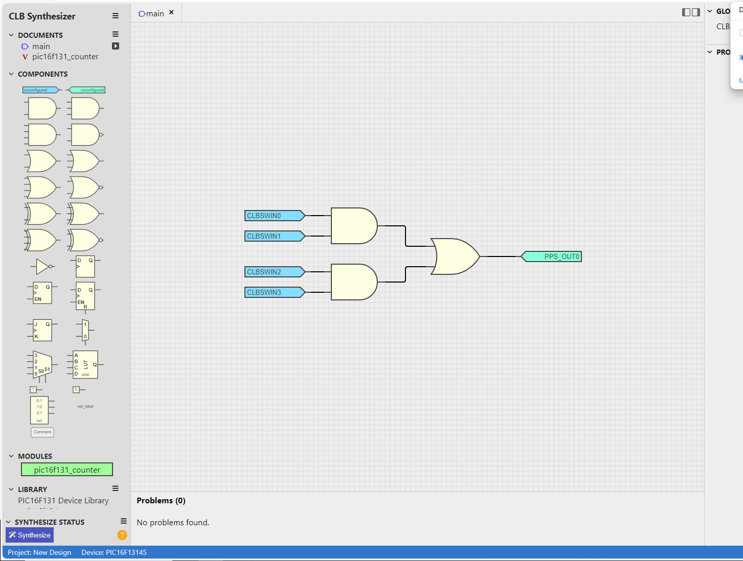
Logikschaltung in einer Simulationssoftware
CLB Synthesizer main DOCUMENTS pic16f131_counter COMPONENTS unconfigur CLBSWIN0 CLBSWIN1 CLBSWIN2 CLBSWIN3 Q EN J K S Q LUT not_label MODULES pic16f131_counter LIBRARY PIC16F131 Device Library Problems (0) No problems found. Synthesize Status Project: New Design Device: PIC16F13145 PPS_OUT8
in „Microchip CLB – erste Versuche zur „FPGA-Zelle“ im Achtbitter“ · Mikrocontroller und Digitale Elektronik · · Screenshots
-
Datei
Konsolenausgabe.txt
driver understands Ada... no checking how to compare bootstrapped objects... cmp --ignore-initial=16 $$f1 $$f2 checking for objdir... .libs checking whether to use debuginfod... auto checking for debuginfod_begin in -ldebuginfod... no checking whether debuginfod_begin is declared... no configure: WARNING
in „cannot read spec file 'device-specs/specs-atmega4808'“ · Mikrocontroller und Digitale Elektronik ·
-
PDF
rfm12b_programmieranleitung.pdf
..f0: Set DQD threshold 8. FIFO and Reset Mode Command bit 15 14 13 12 11 10 9 8 7 6 5 4 3 2 1 0 POR 1 1 0 0 1 1 1 0 f3 f2 f1 f0 sp al ff dr CA80h f3..f0: Set FIFO interrupt level sp: Select the length of
in „RFM 12B Projekt“ · Mikrocontroller und Digitale Elektronik ·
-
Datei
Nexys3_Master.ucf
IOSTANDARD = "LVCMOS33"; #Bank = 1, Pin name = IO_L29N_A22_M1A14, Sch name = P30-A22 #NET "MemAdr<24>" LOC = "C17" | IOSTANDARD = "LVCMOS33"; #Bank = 1, Pin name = IO_L29P_A23_M1A13, Sch name = P30-A23 #NET "MemAdr<25>" LOC = "F16" |
in „Anfänger hat Probleme mit parallelen Prozessen“ · FPGA, VHDL & Co. ·
-
PDF
arm.pdf
D14PID2021 D14 POFPGA_STATUSS 11PID20P0.22 / RTS1 / MCIDAT0 / TD1 P3.15 / D15PID2028 D15 COC29 POAADC0 1PID20P0.23 / AD0.0 / I2SRX_CLK / CAP3.0 P3.16 / D16 / PWM0.1 / TXD1ID20137 D16 100n POADC1 1PID2016 PID20143 D17 PIC2901 PIC2902 ADC1 14 P0.24 /
in „ARM Board Layout“ · Platinen ·
-
PDF
12-2012_Weihnachtsbaum.pdf
Um möglichst viele abwechslungsreiche Effekte speichern zu kön- 0 5 4 3 2 1 0 7 6 5 4 3 2 1 0 nen, hat der Autor für die Steuerung den Mikro- B A A A A A A C C C C C C C C 16 15 14 13 12 11 10 9 8 7 6 5 4 3 2 1 controller PIC18F2685 von Microchip gewählt, der K1 einen 96 KB
in „Alternative zu PIC18F2685“ · Mikrocontroller und Digitale Elektronik ·