-
Datei
bma020.h
#ifndef BMA020_H #define BMA020_H #include <stm32f4xx.h> #include <stm32f4xx_gpio.h> #include <stm32f4xx_rcc.h> #include <stm32f4xx_usart.h> #include <stm32f4xx_spi.h> #include <stm32f4xx_conf.h> /************************Defines******************
in „STM32F4: BMA020 per SPI“ · Mikrocontroller und Digitale Elektronik ·
-
Datei
main.c
IRQHandler() /********************************************************************************/ { uint8_t ui; int16_t i1; uint32_t ind; uint8_t c; SPI_I2S_ClearITPendingBit(SPI2,SPI_I2S_IT_RXNE); spiisrcnt++; i2sval =SPI2->DR; if(! stopsampling){ hbuf[hbufp]=(i2sval); hbufp++; } if(hbufp==HBUFLEN){ //isr_aus
in „Hook up a MEMS microphone to the I2S of a Cortex M4“ · Projekte & Code ·
-
PDF
STM32VL_Manual.pdf
environment you can refer to the UM0919 User Manual: STM32VLDiscovery available at www.st.com/stm32-discovery. 8. Select Download from the Flash menu Figure 8. Flash download window 9. Your project is successfully programmed and verified. Figure 9. Console
in „STM32VL mit uVision flashen“ · Mikrocontroller und Digitale Elektronik ·
-
Datei
stm32f103c8t6_lcd_ili9341.c
retval None */ void LCD_DrawBMP(uint32_t BmpAddress) { uint32_t i = 0, size = 0; /* Read bitmap size */ sFLASH_ReadBuffer((uint8_t*)&size, BmpAddress + 2, 4); /* get bitmap data address offset */ sFLASH_ReadBuffer((uint8_t*)&i, BmpAddress + 10, 4); size = (size - i)/2; sFLASH_StartReadSequence(BmpAddress
in „ili9341 initialisieren“ · Mikrocontroller und Digitale Elektronik ·
-
Datei
spi_ringbuffer.c
#include "stm32f10x_rcc.h" #include "stm32f10x_tim.h" #include "stm32f10x_spi.h" #include "stm32f10x_gpio.h" #include "stm32f10x_it.h" #include "misc.h" #define FLA_BUFFER_SIZE 16 typedef enum { flash_WRSR = 0x01
in „STM32 SPI Interrupt Ringpuffer verliert Zeichen“ · Mikrocontroller und Digitale Elektronik ·
-
PDF
UART_Test.pdf
Configuration Report 1. Description 1.1. Project Project Name UART_Test Board Name custom Generated with: STM32CubeMX 6.2.1 Date 08/02/2021 1.2. MCU MCU Series STM32F1 MCU Line STM32F103 MCU name STM32F103RBTx MCU Package LQFP64 MCU Pin number 64 1.3. Core(s) information Core(s) Arm Cortex-M3 Page 1 UART_Test
in „STM32F1 HAL UART Senden nicht“ · Mikrocontroller und Digitale Elektronik ·
-
Datei
User_Setup.h
#define NUCLEO_64_TFT //#define NUCLEO_144_TFT // STM32 8 bit parallel only: // If STN32 Port A or B pins 0-7 are used for 8 bit parallel data bus bits 0-7 // then this will improve rendering performance by a factor of ~8x //#define STM_PORTA_DATA_BUS //#define STM_PORTA_DATA_BUS // Tell the library to use 8 bit parallel mode (otherwise SPI is assumed) //#define TFT_PARALLEL_8_BIT // Display type - only define if RPi display //#define RPI_DISPLAY_TYPE // 20MHz
in „Powerpins am ESP32-DevKitC, WDT_RTC_RESET“ · Mikrocontroller und Digitale Elektronik ·
-
Datei
Verlauf.txt
0xf -expected-id 0x1ba01477 Debug: 93 31 hla_tcl.c:118 jim_hl_newtap_cmd(): Creating New Tap, Chip: STM32F107VCTx, Tap: cpu, Dotted: STM32F107VCTx.cpu, 8 params Debug: 94 31 hla_tcl.c:128 jim_hl_newtap_cmd(): Processing option: -irlen Debug: 95 31 hla_tcl.c:128 jim_hl_newtap_cmd(): Processing option:
in „SW4STM32 hängt bei in procedure 'ocd_bouncer'“ · Mikrocontroller und Digitale Elektronik ·
-
Datei
system_stm32f30x.c
whenever the core clock is changed * during program execution. * * 2. After each device reset the HSI (8 MHz) is used as system clock source. * Then SystemInit() function is called, in "startup_stm32f30x.s" file, to * configure the system clock before to branch to main program. * * 3. If the system clock
in „STM32 Takt Frage“ · Mikrocontroller und Digitale Elektronik ·
-
PDF
STM32F10xxx_TIM_application_examples.pdf
firmware is provided as TIM example 3 in the STM32F10xxx firmware library, available from the STMicroelectronics microcontrollers website. 8/24 AN2581 - Application note STM32F10xxx TIMx output compare inactive mode 3.3 TIMx output signal behavior
in „STM32 Verwirrung o.O (Timer->CCRx)“ · Mikrocontroller und Digitale Elektronik ·
-
PDF
STM_DEV.pdf
PIKT333 4 PIKT304 6x6 SMD Taster GND GND D D Title Size:A4 Number:7. Revision: File:C:\Projekte\ALTIUM\STM-DEV\JTAG.SchDoc 1 2 3 4 PADL20KPADL10KPSCOSS65P63S01 S05S3A01S93S7A05S0A31 P25S1PS1A2S27A25S03S1 1K DA S1A12 COD12 S6A04S1261A08S0P64S02 S06S4A02S1PS8A06S4A32 P26S1PS1201S8A26S04S0 PADL20APADL10A S0511
in „STM32 Development Board“ · Mikrocontroller und Digitale Elektronik ·
-
Datei
irmp_stm8.diff
SDCC_stm8) +# define SDCC_STM8 #elif defined(unix) || defined(WIN32) || defined(__APPLE__) // Unix/Linux or Windows or Apple # define UNIX_OR_WINDOWS #else @@ -116,6 +118,15 @@ # define PROGMEM # define memcpy_P memcpy +#elif defined(SDCC_STM8) + +# include "stm8s.h" +# define PROGMEM +# define memcpy_P memcpy +# define __attribute__(x) +# define uint_fast8_t uint8_t +# define uint_fast16_t uint16_t + #else # define PROGMEM
-
Datei
system_stm32f30x.c
whenever the core clock is changed * during program execution. * * 2. After each device reset the HSI (8 MHz) is used as system clock source. * Then SystemInit() function is called, in "startup_stm32f30x.s" file, to * configure the system clock before to branch to main program. * * 3. If the system clock
in „STM32F3 - USART 9MBaud“ · Mikrocontroller und Digitale Elektronik ·
-
PDF
mb1045_changed.pdf
C59 0 C57 L 1 C C C LC 0 100nF P 100nF P 100nF P 100nF WW A P K A T_ DO II 0K J JT CT MJ JMJ N 0_ _S_ N0LED0STLINK 1 1 NM MNM LED_STLINK 8 8 T T T R R +3V3 S S S P P U15 R186 R187 1 1 1 1 6 5 3 2 1 2 2 7 6 7 4 88 776 504 302 140 908 70 0 0 3 0 3 STM32F103C8T6 600 700 C C 1 1 04 454 414 414 404 313 31
-
PDF
mb1045_changed_korrigiert.pdf
C59 0 C57 L 1 C C C LC 0 100nF P 100nF P 100nF P 100nF WW A P K A T_ DO II 0K J JT CT MJ JMJ N 0_ _S_ N0LED0STLINK 1 1 NM MNM LED_STLINK 8 8 T T T R R +3V3 S S S P P U15 R186 R187 1 1 1 1 6 5 3 2 1 2 2 7 6 7 4 88 776 504 302 140 908 70 0 0 3 0 3 STM32F103C8T6 600 700 C C 1 1 04 454 414 414 404 313 31
-
Datei
full_make_output_after_make_clean.txt
[CC] STM32F7xx_HAL_Driver/Src/stm32f7xx_hal_lptim.o [CC] STM32F7xx_HAL_Driver/Src/stm32f7xx_hal_i2s.o [CC] STM32F7xx_HAL_Driver/Src/stm32f7xx_hal_dcmi_ex.o [CC] STM32F7xx_HAL_Driver/Src/stm32f7xx_hal_rtc_ex.o
in „Discovery_STM32F746 Linking Problem“ · Mikrocontroller und Digitale Elektronik ·
-
Datei
main.c
zoom_x; } // while(spalte) eff_y += zoom_y; // nächste Zeile } // while(zeile) } void string_ausgabe(int8_t *s, uint8_t farbe) { uint8_t c; while(c = *s++) { schreibe_zeichen_dyn(c,farbe); akt_x += ZEICHEN_LAENGE * zoom_x; } } void schreibe_string(int8_t *s, uint8_t farbe) { zoom_x = zoom_y = 1; string_ausgabe(s,farbe); } void schreibe_string2(int8_t *s, uint8_t farbe) { zoom_x = zoom_y = 2; string_ausgabe(s,farbe); } void schreibe_string3(int8_t *s, uint8_t farbe) { zoom_x = zoom_y = 3; string_ausgabe(s,farbe
in „TFT-direct-drive, WQVGA-TFT an STM32F4“ · Projekte & Code ·
-
Datei
ssi_cgi_handle.c
**** */ /* Includes ------------------------------------------------------------------*/ #include "stm32f10x.h" #include "lwip/debug.h" #include "httpd.h" #include "lwip/tcp.h" #include "fs.h" ///#include "main.h" #include <stdio.h> #include <string.h> #include <stdlib.h> u8 LED1 = 0; u8 LED2 = 0; u8
in „LWIP Webserver“ · Mikrocontroller und Digitale Elektronik ·
-
Datei
main.cpp
**** */ /* Includes ------------------------------------------------------------------*/ #include "stm32f4xx.h" #include "stm32f4xx_conf.h" /** @addtogroup STM32F4xx_StdPeriph_Examples * @{ */ /** @addtogroup GPIO_IOToggle * @{ */ /* Private typedef ---------------------------------------------------
in „Stm32f4 UART löst kein receive Interrupt aus“ · Mikrocontroller und Digitale Elektronik ·
-
PDF
___Voltcraft_PSP1405__SCHALTNETZTEIL_Schaltplan.pdf
220E 33E 1206 R LM7805 2 U1 5 J10 1 - VLM324 C17 33nF AVDD J6 R7 E \ 2 C14 / C2 u 1 1 9 0 1 C1 2 2pinSTM U6C 4 8 / LM324 7 n CN1 D 10 + V R59 470nF 6 VDDI0 0 D 5 1 VSense OUT 8 C8 RX 4 3 9 - - 220E 470nF 2 GND V C12 TX 100nF 1206 1 33nF 1 1 C13 FB1 CN8 V C4 C3 \ R5 1k U6B 4 0 9 8 7 6 5 4 3 2 1 0 9 8 7
in „Labor Schaltnetzteil PSP1405 (Voltcraft) haut es immer die beiden IRF840 durch.“ · Analoge Elektronik und Schaltungstechnik ·
-
PDF
000512411-qs-01-en-SCHALTPLAN_PROGRAM__SCHALTNETZTEIL_PSP_1.pdf
220E 33E 1206 R LM7805 2 U1 5 J10 1 - VLM324 C17 33nF AVDD J6 R7 E \ 2 C14 / C2 u 1 1 9 0 1 C1 2 2pinSTM U6C 4 8 / LM324 7 n CN1 D 10 + V R59 470nF 6 VDDI0 0 D 5 1 VSense OUT 8 C8 RX 4 3 9 - - 220E 470nF 2 GND V C12 TX 100nF 1206 1 33nF 1 1 C13 FB1 CN8 V C4 C3 \ R5 1k U6B 4 0 9 8 7 6 5 4 3 2 1 0 9 8 7
in „Labor Schaltnetzteil PSP1405 (Voltcraft) haut es immer die beiden IRF840 durch.“ · Analoge Elektronik und Schaltungstechnik ·
-
Datei
disco.txt
Mcu.Pin5=PF5 Mcu.Pin50=PE0 Mcu.Pin51=PE1 Mcu.Pin52=VP_SYS_VS_Systick Mcu.Pin6=PC0 Mcu.Pin7=PF11 Mcu.Pin8=PF12 Mcu.Pin9=PF13 Mcu.PinsNb=53 Mcu.UserConstants= Mcu.UserName=STM32F429ZITx MxCube.Version=4.22.1 MxDb.Version=DB.4.0.221 NVIC.BusFault_IRQn=true\:1\:0\:true\:false\:false\:false NVIC.DebugMonitor_IRQn
in „FMC auf STM32F4 konfigurieren?“ · Mikrocontroller und Digitale Elektronik ·
-
Datei
stm32u5xx_hal.c
_STM32U5xx_HAL_VERSION_SUB2 (0x00U) /*!< [15:8] sub2 version */ #define __STM32U5xx_HAL_VERSION_RC (0x00U) /*!< [7:0] release candidate */ #define __STM32U5xx_HAL_VERSION ((__STM32U5xx_HAL_VERSION_MAIN << 24U)\ |(__STM32U5xx_HAL_VERSION_SUB1 << 16U)\ |(__STM32U5xx_HAL_VERSION_SUB2 << 8U )\ |(__STM32U5xx_HAL_VERSION_RC)) #define VREFBUF_TIMEOUT_VALUE 10U /* 10 ms (to be confirmed) */ /** * @} */ /* Private macro --
in „STM32U599 reagiert nicht: Keine Funktion auf dem Custom Board“ · Mikrocontroller und Digitale Elektronik ·
-
Datei
STM32_Init.c
/*---------------------------------------------------------------------------- * Name: STM32_Init.c * Purpose: STM32 peripherals initialisation * Version: V1.27 * Note(s): *---------------------------------------------------------------------------- * This file is part of the uVision/ARM
in „Frage zu ST-Mikrocontrollern mit eMios“ · Mikrocontroller und Digitale Elektronik ·
-
Datei
patch_openocd_for_h7.txt
Makefile.am to openocd-0.10.0/src/flash/nor/Makefile.am cd openocd-0.10.0/contrib/loaders/flash download stm32h7x.S to openocd-0.10.0/contrib/loaders/flash/stm32h7x.S http://openocd.zylin.com/#/c/4181/3/contrib/loaders/flash/stm32h7x.S (File Path link) http://openocd.zylin.com/gitweb?p=openocd.git;hb=refs%2Fchanges%2F81%2F4181%2F3;f=contrib%2Floaders%2Fflash%2Fstm32h7x.S (gitweb link) http://openocd.zylin.com/gitweb?p=openocd.git;a=blob_plain;f=contrib/loaders/flash/stm32h7x.S;hb=refs/changes/81/4181/3 (raw link) store stm32h7x.S to openocd-0.10.0/contrib/loaders/flash
in „Nucleo-H743ZI in Linux und mit stlink 1.5.0“ · Mikrocontroller und Digitale Elektronik ·
-
Datei
main.c
//-------------------------------------------STM32F4_DMA_PORT------------------------------------------------------- /* Beschreibung: * Simples Beispiel f�r einen DMA-Transfer, welcher eine LED zum Blinken bringt. */ /* Hinweis zum Clock fuer 8MHz Quarz, damit er auf 168MHz l�uft (betrifft das stm32F4Discovery): in der system_stm32f4xx.c muss eingetragen sein: PLL_M = 8 in der stm32f4xx.h muss eingetragen sein: HSE_VALUE = 8000000 */ #include <stdio.h> #include <stdlib.h> #include <string.h>
in „STM3F4 Bitstream erzeugen“ · Mikrocontroller und Digitale Elektronik ·
-
Datei
stm32l1xx_conf.h
"stm32l1xx_adc.h" //#include "stm32l1xx_crc.h" #include "stm32l1xx_comp.h" //#include "stm32l1xx_dac.h" #include "stm32l1xx_dbgmcu.h" #include "stm32l1xx_dma.h" #include "stm32l1xx_exti.h" #include "stm32l1xx_flash.h" #include "stm32l1xx_gpio.h" //#include "stm32l1xx_syscfg.h" //#include "stm32l1xx_i2c.h" //#include "stm32l1xx_iwdg.h" #include "stm32l1xx_lcd.h" #include "stm32l1xx_pwr.h" #include "stm32l1xx_rcc.h" #include "stm32l1xx_rtc.h
in „STM32L1 + Makefile. Linkerproblem?“ · Mikrocontroller und Digitale Elektronik ·
-
Datei
stm32f10x_it.c
Timer_RPM++; } /******************************************************************************/ /* STM32F10x Peripherals Interrupt Handlers */ /* Add here the Interrupt Handler for the used peripheral(s) (PPP), for the */ /* available peripheral interrupt handler's name please refer to the startup */ /* file (startup_stm32f10x_xx.s). */ /******************************************************************************/ /** * @brief This function handles PPP interrupt request. * @param None * @retval None */ /*void PPP_IRQHandler
in „Stm32: Übertragungsfehler bei dauerhafter Übertragung“ · Mikrocontroller und Digitale Elektronik ·
-
Datei
_xx.emProject.txt
Executable" /> <folder Name="Internal Files"> <file file_name="$(StudioDir)/samples/SEGGER_THUMB_Startup.s" /> <file file_name="../Cortex_M_Startup.s" /> </folder> <configuration CMSIS_CORE="Yes" Name="xx" c_preprocessor_definitions="USE_HAL_DRIVER;STM32L412xx;USE_HAL_DRIVER;STM32L412xx" c_user_include_directories
in „NUCLEO-L412KB: Läuft nur mit Debugger an“ · Mikrocontroller und Digitale Elektronik ·
-
Datei
stm32h753bit6.cpp
***************/ INTERRUPT_VECTOR const STM32H753BIT6::s_interruptTable STM32H753BIT6::c_interruptTable = { (uint32) ISR_WWDG, // 0x040 Window Watchdog (uint32) ISR_PVD_PVM, // 0x044 PVD through EXTI Line (uint32) ISR_RTC_TAMPER_CSSLSE, // 0x048
in „Virtual Function Elimination ARM GCC“ · Mikrocontroller und Digitale Elektronik ·
-
PDF
BLDC_motors.pdf
drive the 3 JY21L high speed power MOSFET drivers which are connected to the JY01-places of pin 7, 8 (first JY21L-IC), pin 9, 10 (second JY21L-IC) and pin 11, 12 (third JY21L-IC). To do this, we use the STM32 NUCLEO-F401RE prototype board and the port-pins CH1(PA6), CH2(PA7), CH3(PB0), sw1(PB6), sw2
in „BLDC Ansteuerung“ · Mikrocontroller und Digitale Elektronik ·
-
Datei
rtc_main.c
configured, this is done through SystemInit() function which is called from startup file (startup_stm32f2xx.s) before to branch to application main. To reconfigure the default setting of SystemInit() function, refer to system_stm32f2xx.c file */ /* Initialize LEDs mounted on STM322xG-EVAL board ----
in „RTC Initialisierung auf STM32F4 geht nicht :-(“ · Mikrocontroller und Digitale Elektronik ·
-
Datei
all_c_h_s_files_in_proj_dir.txt
./STM32F7xx_HAL_Driver/Src/stm32f7xx_hal_rcc.c ./STM32F7xx_HAL_Driver/Src/stm32f7xx_hal_cortex.c ./STM32F7xx_HAL_Driver/Src/stm32f7xx_hal_lptim.c ./STM32F7xx_HAL_Driver/Src/stm32f7xx_hal_i2s.c ./STM32F7xx_HAL_Driver
in „Discovery_STM32F746 Linking Problem“ · Mikrocontroller und Digitale Elektronik ·
-
Datei
pinouts.txt
/* ################################################################## STM8S103F3P6 Pinout ################################################################## ------------ UART1_CK / TIM2_CH1 / PD4 | 1 20 | PD3 / AIN4 / TIM2_CH2 / ADC_ETR UART1_TX / AIN5 / PD5 | 2 19 | PD2
in „STM8S Minimumboard + SSD1306 OLED Display“ · Projekte & Code ·
-
Datei
make_d_ohne_shEXE.txt
file `src/startup_stm32f4xx.s'. Looking for an implicit rule for `src/startup_stm32f4xx.s'. Trying pattern rule with stem `startup_stm32f4xx.s'. Trying implicit prerequisite `src/startup_stm32f4xx.s,v'. Trying pattern rule
in „Makefile STM32 Discovery“ · Mikrocontroller und Digitale Elektronik ·
-
Datei
main.c
/ I2C_AcknowledgeConfig(MPU6050_I2C, ENABLE); // EXT_CRT_SECTION(); } void MPU6050_GetRawAccelGyro(s16* AccelGyro) { u8 tmpBuffer[14]; u8 i; MPU6050_I2C_BufferRead(MPU6050_DEFAULT_ADDRESS, tmpBuffer, MPU6050_RA_ACCEL_XOUT_H, 14); /* Get acceleration */ for (i = 0; i < 3; i++) AccelGyro[i] = ((s16) ((u16) tmpBuffer[2 * i] << 8) + tmpBuffer[2 * i + 1]); /* Get Angular rate */ for (i = 4; i < 7; i++) AccelGyro[i - 1] = ((s16) ((u16) tmpBuffer[2 * i] << 8) + tmpBuffer[2 * i + 1]); }
in „STM32F103 + I2C + MPU6050 - DMA“ · Mikrocontroller und Digitale Elektronik ·
-
PDF
Resources_STM32WL_UFQFPN48_REF_BOARD_Low_Power_High_Band_868-915MHz.pdf
PIC205 POPC1313 38 83PC13P 1IPU1VDD PB5 PIN116 15 PA2 PIC206 15 VDD PB6 16 PA1 16 PA3 PIN117 17 PB8 PIC207 17 P1 PA4 PIN118 18 PB4 PIC208 18 STM32WLxx_QFN48 C5 UART_RX PIN119 19 PA8 PIC209 19 P2 100nF 3IPU3 D PIN120 PIC200 VBAT A UART_TX 20 PA5 20 41 x CON20 CON20 14VDDAP ( S L1101LIP 201LIP V 600R
in „STM32WLE5CCU6 LoRa-Antennenendesign review“ · HF, Funk und Felder ·
-
Datei
nrf24l01.c
Prototypen ----------- */ static void RF_FlushRX(); static void RF_FlushTX(); static uint8_t RF_ReadRegSingle(uint8_t); static void RF_WriteRegSingle(uint8_t, uint8_t); static void RF_WriteRegMulti(uint8_t, const uint8_t*, size_t); static uint8_t RF_ReadRegSingle(uint8_t); static void RF_ReadRegMulti
in „GCC Optimierung killt Funktion“ · Mikrocontroller und Digitale Elektronik ·
-
PDF
STM32_F4VE_SCHEMATIC.PDF
PIU2034PC5/ADC12_IN15 PIR701 LED 指示灯 PCPC6 PIU2063 PIU2050 5V J2J2 5V BOOT0 BOOT1 启动方式 PCP7 PIU2064PC6/TIM8_CH1/I2S3_MCK/SDIO_D6/(TIM3_CH1) VDD_1 PIU2075 3V3 PIJ201 PIJ202 SDIO_D00 PC8 PIU2065PC7/TIM8_CH2/I2S3_MCK/SDIO_D7(TIM3_CH2) VDD_2 PIU20100 GND PIJ203 1 2 PIJ204 0 无关 用户闪存 NLSDIO01 PC9 PIU2066PC8/TIM8
in „Neues Entwicklungsboard STM32F407“ · Mikrocontroller und Digitale Elektronik ·
-
PDF
STM32_F4VE_SCHEMATIC.PDF
PIU2034PC5/ADC12_IN15 PIR701 LED 指示灯 PCPC6 PIU2063 PIU2050 5V J2J2 5V BOOT0 BOOT1 启动方式 PCP7 PIU2064PC6/TIM8_CH1/I2S3_MCK/SDIO_D6/(TIM3_CH1) VDD_1 PIU2075 3V3 PIJ201 PIJ202 SDIO_D00 PC8 PIU2065PC7/TIM8_CH2/I2S3_MCK/SDIO_D7(TIM3_CH2) VDD_2 PIU20100 GND PIJ203 1 2 PIJ204 0 无关 用户闪存 NLSDIO01 PC9 PIU2066PC8/TIM8
in „STM32F407 Black und Arduino“ · Mikrocontroller und Digitale Elektronik ·
-
Datei
i2c_simple_stm32.c
Variante von I2C-Routinen // als Übung zur Inbetriebnahme // angelehnt an: http://eliaselectronics.com/stm32f4-tutorials/stm32f4-i2c-master-tutorial/ // // 22.12.13 Nicolas #ifdef STM32F10x #include "stm32f10x_gpio.h" #include "stm32f10x_rcc.h" #include "stm32f10x_i2c.h" #elif STM32F4XX #define STM32F4xx #include "stm32f4xx_gpio.h" #warning not implemnted and tested for STM32F4xx #else #error "unknown MCU" #endif #include <stdio.h> // Nur zum testen #include "misc.h" #include "i2c_simple.h" static uint8_t i2c_status
in „STM32 I2C mit EEPROM - funktioniert nur zuverlässig mit Bus-Sniffer“ · Mikrocontroller und Digitale Elektronik ·
-
Datei
main.c
/* Includes ------------------------------------------------------------------*/ #include "stm32f2xx.h" #include "stm32_eval.h" #include "stm322xg_eval_lcd.h" #include "stm32f2xx_spi.h" #include <stdio.h> GPIO_InitTypeDef GPIO_InitStruct; SPI_InitTypeDef SPI_InitStructure; static uint8_t key_state
in „STM32 SPI Mosi Pegel zu niedrig“ · Mikrocontroller und Digitale Elektronik ·
-
Datei
usb_vcp.c
/* originally based on W.S. VCP implenentation while it should be still compatible with the original one found at http://stefanfrings.de/stm32/STM32F103_usb_test.zip Several changes are made to be more flexible Tested on various
in „STM32 USB Übertragungsproblem mit Code von S.F.“ · Mikrocontroller und Digitale Elektronik ·
-
Datei
log.txt
------------------------CONFIGURATION: https://docs.platformio.org/page/boards/ststm32/nucleo_f303k8.html PLATFORM: ST STM32 (16.1.0) > ST Nucleo F303K8 HARDWARE: STM32F303K8T6 72MHz, 12KB RAM, 64KB Flash DEBUG: Current (stlink) On-board (stlink) External (blackmagic, cmsis-dap, jlink) PACKAGES: - framework-arduinoststm32
in „Nucleo + PlatformIO upload Problem“ · Mikrocontroller und Digitale Elektronik ·
-
Datei
irmpconfig.h
------------------------------------------------------------------- * Change hardware pin here for STM8 *--------------------------------------------------------------------------------------------------------------------------------------------------- */ #elif defined (SDCC_STM8) // use PA1 as IR input on STM8 # define IRMP_PORT_LETTER A # define IRMP_BIT_NUMBER 1 /*--------------------------------------------------------------------------------------------------------------------------------------------
in „IRMP - Infrared Multi Protocol Decoder“ · Projekte & Code ·
-
 Bild
Bild
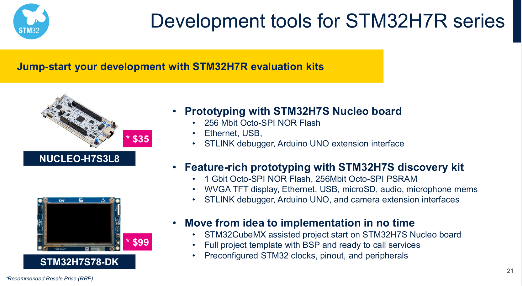
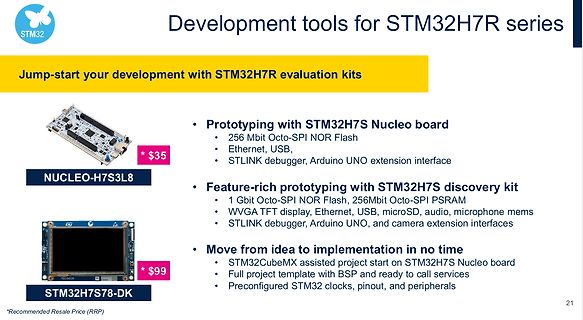
Präsentation von STM32H7R Entwicklungskits
Development tools for STM32H7R series Jump-start your development with STM32H7R evaluation kits NUCLEO-H7S3L8 $35 Prototyping with STM32H7S Nucleo board 256 Mbit Octo-SPI NOR Flash Ethernet, USB, STLINK debugger, Arduino UNO extension interface Feature-rich prototyping with STM32H7S discovery kit 1 Gbit Octo-SPI NOR Flash, 256Mbit Octo-SPI PSRAM WVGA TFT display, Ethernet, USB, microSD, audio, microphone mems STLINK debugger, Arduino UNO, and camera extension interfaces STM32H7S78
in „Neue STM32H7-Variante, Eclipse-Daten zur IoT-Adoption und neue Kameras“ · Mikrocontroller und Digitale Elektronik · · Screenshots
-
Datei
usart_stm32f4xx.c
DMA aendern * -> wird spaeter hoechstens fuer syscalls-Umleitung benoethigt */ void usart_putc(uint8_t c) { USART_TypeDef* USARTx; switch( USART_NO ) { case uart_STM32F4XX_USART_none: return; case uart_STM32F4XX_USART2_PA2_PA3: USARTx = USART2; break; case uart_STM32F4XX_USART3_PB10_PC5: USARTx = USART3
in „STM32F446: USART DMA-Transfer“ · Mikrocontroller und Digitale Elektronik ·
-
PDF
PitschLight_Doku_V1.2.pdf
Ein Full-Screen AmbiLight mit bis zu 312 LEDs auf Basis des TVP5150AM1 Video Prozessors und eines STM32F4discovery boards Stand: Version 1.2, November 2014 Das Foto stammt von Pat Wat (frankp) So sieht‘s aus wenn es funktioniert Disclaimer /***************************************************** * * Control
in „Ambilight mit STM32F4discovery und TVP5150AM1“ · Mikrocontroller und Digitale Elektronik ·
-
Datei
stm32f4xx_spi.h
((uint8_t)0x58) #define IS_SPI_I2S_CONFIG_IT(IT) (((IT) == SPI_I2S_IT_TXE) || \ ((IT) == SPI_I2S_IT_RXNE) || \ ((IT) == SPI_I2S_IT_ERR)) #define SPI_I2S_IT_OVR ((uint8_t)0x56) #define SPI_IT_MODF ((uint8_t)0x55
in „STM32F4XX SPI Slave“ · Mikrocontroller und Digitale Elektronik ·
-
Datei
Release_Notes.html
font-size: 10pt; font-family: Verdana;"><span style="font-style: italic;">Add new definition for I2S Audio Clock frequencies "I2S_AudioFreq_192k".</span></span></li> </ul> <li class="MsoNormal"><span style="font-size: 10pt; font-family: Verdana;">stm32f10x_tim.h/.c</span></li> <ul><li class="MsoNormal
in „STM32F10x Std Peripherals Lib V3.5.0 vs. V3.6.1“ · Mikrocontroller und Digitale Elektronik ·