-
Datei
main.c
RCC_APB1Periph_TIM4, ENABLE); RCC_APB1PeriphClockCmd(RCC_APB1Periph_TIM3, ENABLE); // Timer2 konfigurieren TIM_TimeBaseInitTypeDef TIM_TimeBase_InitStructure; TIM_TimeBase_InitStructure.TIM_ClockDivision = TIM_CKD_DIV1; TIM_TimeBase_InitStructure.TIM_CounterMode = TIM_CounterMode_Up; TIM_TimeBase_InitStructure.TIM_Period = 42000; TIM_TimeBase_InitStructure.TIM_Prescaler = 300; TIM_TimeBaseInit(TIM2, &TIM_TimeBase_InitStructure); TIM_ITConfig(TIM2, TIM_IT_Update, ENABLE); TIM_TimeBaseInit(TIM3, &TIM_TimeBase_InitStructure); TIM_ITConfig(TIM3
in „stm32f103 3phase-generator“ · Mikrocontroller und Digitale Elektronik ·
-
Datei
intflash.c
******/ void IntFlash_Init(void) { // Setze Anzahl Master Clock Ciycles pro 1.5 Microsecond AT91C_BASE_MC->MC_FMR = (((3 * MCK) / 2000000 + 2) << 16) | AT91C_MC_FWS_1FWS; } RAMFUNC RETCODE IntFlash_Write(UINT32 addr, UINT32 len, UINT32 *data) { volatile UINT32 statreg; volatile UINT32 *dest = (UINT32
in „Timing-Problem beim Schreiben von internem Flash (AT91SAM7S256)“ · Mikrocontroller und Digitale Elektronik ·
-
Datei
vmware-14.1-drivers.patch
KERNEL_VERSION(5, 0, 0) struct timeval tv; +#else + struct timespec64 ts; +#endif uint64 monotime, uptime, upBase, monoBase; int64 diff; uint32 version; @@ -1645,13 +1653,21 @@ monoBase = uptimeState.monotimeBase; } while (!VersionedAtomic_EndTryRead(&uptimeState.version, version)); +#if LINUX_VERSION_CODE < KERNEL_VERSION(5, 0, 0) do_gettimeofday(&tv); +#else + ktime_get_real_ts64(&ts); +#endif upBase = Atomic_Read64(&uptimeState.uptimeBase); monotime = (uint64)(jifs - jifBase) * (UPTIME_FREQ / HZ); monotime += monoBase; +#if LINUX_VERSION_CODE < KERNEL_VERSION(5, 0, 0) uptime = tv.tv_usec * (UPTIME_FREQ
in „VMware Workstation 14.1 auf Linux Kernel 5.x: Compilefehler vmmon und vmnet“ · PC Hard- und Software ·
-
Datei
main.c
------*/ /* Private variables ---------------------------------------------------------*/ TIM_TimeBaseInitTypeDef TIM_TimeBaseStructure; TIM_OCInitTypeDef TIM_OCInitStructure; TIM_BDTRInitTypeDef TIM_BDTRInitStructure; uint16_t CCR1_Val = 32767; uint16_t CCR2_Val = 24575; uint16_t CCR3_Val = 16383; uint16
in „STM32 Six-step PWM signal generation using TIM1“ · Mikrocontroller und Digitale Elektronik ·
-
Datei
main.c
------*/ /* Private variables ---------------------------------------------------------*/ TIM_TimeBaseInitTypeDef TIM_TimeBaseStructure; TIM_OCInitTypeDef TIM_OCInitStructure; TIM_BDTRInitTypeDef TIM_BDTRInitStructure; uint16_t CCR1_Val = 32767; uint16_t CCR2_Val = 24575; uint16_t CCR3_Val = 16383; uint16
in „STM32F1 Brushless Motor Steuerung“ · Mikrocontroller und Digitale Elektronik ·
-
PDF
Datenblatt_VPC3_CLF3_UM300.pdf
memory is divided into 256 segments, with 8 bytes each. Otherwise in the 4K Byte mode the segment base addresses starts at multiple of 16. Addressing by the user is done directly, however, the internal Micro Sequencer (MS) addresses the RAM by means of the so-called base- pointer. The base-pointer can
in „Profibus an Mikrocontroller“ · Mikrocontroller und Digitale Elektronik ·
-
Datei
usb_vcp.c
volatile bool transmitting; /* Cortex-M NVIC Register */ #define NVIC_ISER (*(volatile uint32_t (*) [16])(0xE000E100)) #define NVIC_ICER (*(volatile uint32_t (*) [16])(0xE000E180)) /* All USB register are 16 bit wide but have to be accessed as 32 bit. */ /* USB device (base address 0x4000 5C00) */ #define USB_BASE 0x40005C00 #define USB_EpRegs(x) (*(volatile uint32_t *)(USB_BASE + 4*(x))) #define USB_EP0R (*(volatile uint32_t *)(USB_BASE + 0x00)) #define USB_EP1R (*(volatile uint32_t *)(USB_BASE + 0x04)) #define
in „STM32 USB Übertragungsproblem mit Code von S.F.“ · Mikrocontroller und Digitale Elektronik ·
-
Datei
usb_vcp.c
volatile bool transmitting; /* Cortex-M NVIC Register */ #define NVIC_ISER (*(volatile uint32_t (*) [16])(0xE000E100)) #define NVIC_ICER (*(volatile uint32_t (*) [16])(0xE000E180)) /* All USB register are 16 bit wide but have to be accessed as 32 bit. */ /* USB device (base address 0x4000 5C00) */ #define USB_BASE 0x40005C00 #define USB_EpRegs(x) (*(volatile uint32_t *)(USB_BASE + 4*(x))) #define USB_EP0R (*(volatile uint32_t *)(USB_BASE + 0x00)) #define USB_EP1R (*(volatile uint32_t *)(USB_BASE + 0x04)) #define
in „STM32 USB Übertragungsproblem mit Code von S.F.“ · Mikrocontroller und Digitale Elektronik ·
-
Datei
mode.pas
... 115200 } Var R: Byte; Divisor: Integer; Begin { -- save current settings } R := Port[I2C_UART_BASE + I2C_UART_LCR]; { --- allow access special registers 0 and 1 } Port[I2C_UART_BASE + I2C_UART_LCR] := 128; { --- set divisor for baud rate (for 14.7456 MHz crystal) } { XTALFREQ / (BaudRate * 16) = 14745600 / BaudRate / 16 = 921600 / BaudRate } Divisor := Trunc( 9216 / (BaudRate/100) ); Port[I2C_UART_BASE + $00] := Divisor and $FF; Port[I2C_UART_BASE + $01] := (Divisor shr 8) and $FF; { --- disallow access special registers
in „CP/M auf ATmega88“ · Mikrocontroller und Digitale Elektronik ·
-
Datei
main.c
1000; if (HAL_HRTIM_BurstModeConfig(&hhrtim, &pBurstModeCfg) != HAL_OK) { Error_Handler(); } pTimeBaseCfg.Period = 50000; pTimeBaseCfg.RepetitionCounter = 0x00; pTimeBaseCfg.PrescalerRatio = HRTIM_PRESCALERRATIO_DIV2; pTimeBaseCfg.Mode = HRTIM_MODE_CONTINUOUS; if (HAL_HRTIM_TimeBaseConfig(&hhrtim, HRTIM_TIMERINDEX_MASTER
in „STM32H7: HRTIM im DMA Burst Mode für PWM Waveform Erzeugung einsetzen“ · Mikrocontroller und Digitale Elektronik ·
-
Datei
DSP2802x_EPwm.h
ifdef __cplusplus extern "C" { #endif //---------------------------------------------------- // Time base control register bit definitions */ struct TBCTL_BITS { // bits description Uint16 CTRMODE:2; // 1:0 Counter Mode Uint16 PHSEN:1; // 2 Phase load enable Uint16 PRDLD:1; // 3 Active period load Uint16
in „TI spezifische Befehle zB .half“ · Mikrocontroller und Digitale Elektronik ·
-
PDF
Servicemanual_Hameg_HM_305-2.pdf
rectangle with a horizontal and a vertical center line should be visible. -Locate and identify VR7002 (16A) and VR7003 (16B) on Digital-Board. -Adjust VR7002 (16A) for exactly 6 div. rectangle Y amplitude. -Adjust VR7003 (16B) for symmetrical vertical position (horizontal lines 1 division above and below the graticule limits. -If necessary repeat adjusting VR7002 (16A) and VR7003 (16B). -Locate and identify VR7001 (16C) on Digital-Board. -Locate and identify R4851 (16D) on Main-Board. -Adjust R4851 (16D) for exactly 8 div. rectangle X amplitude. -Adjust VR7001 (16C
in „Oszilloskop - Bildröhre läuft unzuverlässig“ · Analoge Elektronik und Schaltungstechnik ·
-
Datei
main.c
STELLARIS_ARM_CORTEX_M4) void timer1_init (void) { SysCtlPeripheralEnable(SYSCTL_PERIPH_TIMER1); TimerConfigure(TIMER1_BASE, TIMER_CFG_32_BIT_PER); TimerLoadSet(TIMER1_BASE, TIMER_A, (F_CPU / F_INTERRUPTS) -1); IntEnable(INT_TIMER1A); TimerIntEnable(TIMER1_BASE, TIMER_TIMA_TIMEOUT); TimerEnable(TIMER1_BASE, TIMER_A); //
in „IRMP-Anwendung“ · Mikrocontroller und Digitale Elektronik ·
-
PDF
MC9S12XF512.pdf
(at address vector base + 0x00F8). 1. The vector base is a 16-bit address which is accumulated from the contents of the interrupt vector base register (IVBR, used as upper byte) and 0x00 (used as lower byte). 2. The IRQ interrupt
in „Wie oft kann ein µC programmiert werden?“ · Mikrocontroller und Digitale Elektronik ·
-
PDF
MC9S12XF512.pdf
(at address vector base + 0x00F8). 1. The vector base is a 16-bit address which is accumulated from the contents of the interrupt vector base register (IVBR, used as upper byte) and 0x00 (used as lower byte). 2. The IRQ interrupt
in „Probleme beim Ansteuern eines EEPROM über SPI“ · Mikrocontroller und Digitale Elektronik ·
-
Datei
HallSensorTimer.c
GPIOB, GPIO_PinSource5, GPIO_AF_TIM3); RCC_APB1PeriphClockCmd(RCC_APB1Periph_TIM3, ENABLE); // timer base configuration // 126 => 3,5s till overflow ; 285,714kHz TimerClock [36MHz/Prescaler] TIM_TimeBaseStructure.TIM_Prescaler = 126; TIM_TimeBaseStructure.TIM_CounterMode = TIM_CounterMode_Up; TIM_TimeBaseStructure.TIM_Period = 65535; TIM_TimeBaseStructure.TIM_ClockDivision = 0; TIM_TimeBaseStructure.TIM_RepetitionCounter = 0; TIM_TimeBaseInit(TIM3, &TIM_TimeBaseStructure); // enable hall sensor // T1F_ED will be connected to HallSensoren Imputs
in „STM32F4 BLDC mit Hall Sensoren“ · Mikrocontroller und Digitale Elektronik ·
-
PDF
ss12.pdf
PACKAGE CODE BASE QUANTITY DELIVERY MODE SS16-E3/61T 0.064 61T 1800 7" diameter plastic tape and reel SS16-E3/5AT 0.064 5AT 7500 13" diameter plastic tape and reel SS16HE3_B/H (1) 0.064 H 1800 7" diameter plastic tape and reel SS16HE3_B/I (1) 0.064 I 7500 13" diameter plastic tape and reel SS16-M3/61T 0.064 61T 1800 7" diameter plastic tape and reel SS16-M3/5AT 0.064 5AT 7500 13" diameter plastic tape and reel SS16HM3_B/H (1) 0.064
in „Identifikation SMD Bauteil“ · Analoge Elektronik und Schaltungstechnik ·
-
Datei
rfm12.c
****************************************************************************/ #define lo8(x) ((uint16_t)(x)&0xff) #define hi8(x) ((uint16_t)(x)>>8) uint16_t crc_ccitt_update(uint16_t crc, uint8_t data) { data ^= lo8 (crc); data ^= data << 4; return ((((uint16_t)data << 8) | hi8 (crc)) ^ (uint8_t)(data
in „RFM12 und STM32F1xx“ · Mikrocontroller und Digitale Elektronik ·
-
PDF
datasheet.pdf
TC half source is mirrored or ‘‘turned around’’ by reference diode supply voltage reference at the base of Q14. The differential D5 and Q26 to provide a 1mA current source for the clamp amplifier formed by Q15, Q16 and feedback transistor Q17 comparator. The inputs to the comparator are similar to the
in „Kann mir jemand bei dieser Platine helfen?“ · Mikrocontroller und Digitale Elektronik ·
-
PDF
The_International_System_of_Units_sp330.pdf
definitions of some units, SI, the two classes of, 3 important units, practical, 45-62 units, SI base, 5-9, 26-37; rem, 17, 19 symbols for, 9 roentgen, 17, 19 units, SI derived, 9-13, 37-40 units, SI supplementary, 39-40 S units, accepted for use with SI, non-SI, second, 6, 16, 29-32, 53-55 SI units
in „Stromangabe in der Einheit At?“ · Mikrocontroller und Digitale Elektronik ·
-
Datei
STM32F100RB_PWM_IO.c
PWM */ // GPIO_PinRemapConfig(GPIO_FullRemap_TIM2, ENABLE); /* Remap Pins if necessary */ TIM_TimeBaseStructure.TIM_Period = 20000 - 1; /* PWM signal length 20 ms */ TIM_TimeBaseStructure.TIM_Prescaler = 24 - 1; /* counter increments every 1 µs */ TIM_TimeBaseInit(TIM2, &TIM_TimeBaseStructure); /* initialize
in „RC Servo Signale mit STM32 einlesen und ausgeben“ · Projekte & Code ·
-
PDF
BC859_BC860_5.pdf
MIN. MAX. UNIT V collector-base voltage open emitter CBO BC859 − −30 V BC860 − −50 V VCEO collector-emitter voltage open base BC859 − −30 V BC860 − −45 V VEBO emitter-base voltage open collector − −5 V C collector current (DC) − −
in „Frage Mosfet“ · Analoge Elektronik und Schaltungstechnik ·
-
Datei
RFID-Reader-Modul.c
UART_BAUD_RATE 9600UL // UART-Baut-Rate #define QBLength_TX 28 // TX-Pufferspeichergröße #define BASE_BIN 2 #define BASE_DEZ 10 #define BASE_HEX 16 #define STRING_LENGTH_MAX 16 #define TONHOEHE_GELESEN 0x16 #define TONHOEHE_GESPEICHERT 0xF0 #define ANZAHL_KARTEN_IDs_IM_EEPROM 4 #define RELAIS_ANZUGSZEIT
in „Attiny2313 eeprom Fragen“ · Mikrocontroller und Digitale Elektronik ·
-
Datei
rc.c
GPIO_Init(GPIOE, &GPIO_InitStructure); GPIO_PinAFConfig(GPIOE, GPIO_PinSource9, GPIO_AF_TIM1); TIM_TimeBaseStructInit(&timbaseinit); timbaseinit.TIM_ClockDivision = TIM_CKD_DIV1; timbaseinit.TIM_CounterMode = TIM_CounterMode_Up; timbaseinit.TIM_Period = 1500; timbaseinit.TIM_Prescaler = (uint16_t)( SystemCoreClock
in „RC Summensignal erzeugen“ · Mikrocontroller und Digitale Elektronik ·
-
Datei
lib_AT91SAM7S256.h
AT91F_SSC_CfgPIO (void) { // Configure PIO controllers to periph mode AT91F_PIO_CfgPeriph( AT91C_BASE_PIOA, // PIO controller base address ((unsigned int) AT91C_PA19_RK ) | ((unsigned int) AT91C_PA16_TK ) | ((unsigned int) AT91C_PA15_TF ) | ((unsigned int) AT91C_PA18_RD ) | ((unsigned int) AT91C_PA20
in „C Datein werden in Eclipse nicht kompiliert“ · Mikrocontroller und Digitale Elektronik ·
-
Datei
DMX_Empfang_ATmega16.c
PORTD &= ~(1<<PD6); } } return 0; } // UART RX complete interrupt ISR(USART_RX_vect) { static uint16_t dmx_channel, dmx_base; uint8_t status, data; int16_t index; // read UART data, also clears interrupt flag status = UCSRA; data = UDR; if (status & (1<<FE)) // frame error { if (data==0) // break -> DMX Reset { dmx_channel=0; dmx_base = (~PINC & 0xFF)+1; // read dip switches which define DMX base address if (~PINA & (1<<PA0)) dmx_base +=256; flag=1; // trigger update } else // rx error dmx_channel++; } else { index = dmx_channel-dmx_base
in „DMX Empfang mit Atmega16 funktioniert leider nicht“ · Mikrocontroller und Digitale Elektronik ·
-
Datei
my_t6963c_1.h
glcd_FONT_WIDTH 6 // pixel width #define glcd_BYTES_PER_ROW 40 // 40 chars per row #define glcd_G_BASE 0x0400 // base address of graphics memory #else // normal font #define glcd_FONT_WIDTH 8 // pixel width #define glcd_BYTES_PER_ROW 30 // 30 chars per row #define glcd_G_BASE 0x0200 // base address of
in „t6963c.h von Mega32 auf AtMega644p“ · Mikrocontroller und Digitale Elektronik ·
-
Datei
t6963c.h
glcd_FONT_WIDTH 6 // pixel width #define glcd_BYTES_PER_ROW 40 // 40 chars per row #define glcd_G_BASE 0x0400 // base address of graphics memory #else // normal font #define glcd_FONT_WIDTH 8 // pixel width #define glcd_BYTES_PER_ROW 30 // 30 chars per row #define glcd_G_BASE 0x0200 // base address of
-
 Bild
Bild
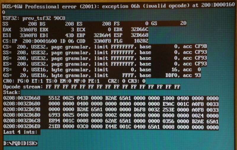
Fehlermeldung eines DOS-Programms mit Speicherabbild
32D668 CS: IP 200:D000160 ID 06 COD 33A0F8 FLG 10202 CS= 200, USE32, page granular, limit FFFFFFFF, base 0, acc CF9B SS= 208, USE32, page granular, limit FFFFFFFF, base 0, acc CF93 DS= 208, USE32, page granular, limit FFFFFFFF, base 0, acc CF93 ES= 208, USE32, page granular, limit FFFFFFFF, base 0, acc CF93 FS= 0, USE16, byte granular, limit 0, base 16, acc 0 GS= 20, USE16, byte granular, limit FFFF, base 0 CR0: PG:0 ET:1 TS:0 EM:0 MP:0 PE:1 CR2: 0 CR3: 0 Upcake stream: FF FF FF Stack: 0208:0032D668 5512 0025 043D
in „Wie Festplatte wieder in Neuzustand versetzen“ · PC Hard- und Software · · Screenshots
-
Datei
stm32f10x_tim.c
) { uint16_t tmpcr1 = 0; /* Check the parameters */ assert_param(IS_TIM_ALL_PERIPH(TIMx)); assert_param(IS_TIM_COUNTER_MODE(TIM_TimeBaseInitStruct->TIM_CounterMode)); assert_param(IS_TIM_CKD_DIV(TIM_TimeBaseInitStruct
in „STM32 - Eclipse, ARM GCC - Funktionsaufruf geht nicht :-(“ · Mikrocontroller und Digitale Elektronik ·
-
Datei
ocl.txt
Unified memory for Host and Device No Minimum alignment for any data type 128 bytes Alignment of base address 32768 bits (4096 bytes) Global Memory cache type None Image support No Local memory type Local Local memory size 32768 (32KiB) Max number of constant args 16 Max constant buffer size 67108864
-
Datei
clang_1.txt
Unified memory for Host and Device No Minimum alignment for any data type 128 bytes Alignment of base address 32768 bits (4096 bytes) Global Memory cache type None Image support No Local memory type Local Local memory size 32768 (32KiB) Max number of constant args 16 Max constant buffer size 67108864
-
PDF
spma014.pdf
Comparison of Variable Sizes Locals of size int Locals of size short int (half word) typedef int BASE; typedef short BASE; BASE foo(BASE last, BASE x, BASE y) BASE foo(BASE last, BASE x, BASE y) { { 0: 2300 movs r3, #0 0: f04f 0c00 mov.w ip, #0; 0x0 2: e002 b.n a <foo+0xa> 4: e004 b.n 10 <foo+0x10>
in „ARM Cortex & GCC: Worauf achten für "optimalen" Code?“ · Mikrocontroller und Digitale Elektronik ·
-
PDF
BC_337-XX.pdf
Order this document SEMICONDUCTOR TECHNICAL DATA by BC337/D Amplifier Transistors NPN Silicon BC337,-16,-25,-40 BC338,-16,-25,-40 COLLECTOR 1 2 BASE 3 EMITTER 1 MAXIMUM RATINGS 2 3 Rating Symbol BC337 BC338 Unit Collector–Emitter Voltage VCEO 45 25 Vdc CASE 29–04, STYLE 17 TO–92 (TO–226AA) Collector–Base
in „Transistorberechnungen“ · Analoge Elektronik und Schaltungstechnik ·
-
PDF
BC337.pdf
Order this document SEMICONDUCTOR TECHNICAL DATA by BC337/D Amplifier Transistors NPN Silicon BC337,-16,-25,-40 BC338,-16,-25,-40 COLLECTOR 1 2 BASE 3 EMITTER 1 MAXIMUM RATINGS 2 3 Rating Symbol BC337 BC338 Unit Collector–Emitter Voltage VCEO 45 25 Vdc CASE 29–04, STYLE 17 TO–92 (TO–226AA) Collector–Base
in „Stromverstaerkung/Grundlagen Bipolartransistor“ · Analoge Elektronik und Schaltungstechnik ·
-
PDF
Ethernet_Hub_LXT914PE.pdf
Unit Interface (AUI) • Programmable DTE/MAU interface on AUI port port and four 10BASE-T transceivers. The AUI port is • Seven integrated LED drivers with four unique mode selectable: DTE mode allows connection of an exter- operational modes nal transceiver (10BASE2, 10BASE5, 10BASE-T
in „Ethernet Transceiver und Hub auf einer Platine verbinden“ · Mikrocontroller und Digitale Elektronik ·
-
Datei
Compiler.h
or compiler. See Compiler.h #endif #include <stdio.h> #include <stdlib.h> #include <string.h> // Base RAM and ROM pointer types for given architecture #if defined(__PIC32MX__) #define PTR_BASE unsigned long #define ROM_PTR_BASE unsigned long #elif defined(__C30__) #define PTR_BASE unsigned short #define ROM_PTR_BASE unsigned short #elif defined(COMPILER_MPLAB_C18) #define PTR_BASE unsigned short #define ROM_PTR_BASE unsigned short long #elif defined(COMPILER_HITECH_PICC18) #define PTR_BASE unsigned short #define
in „Anfängerproblem PIC18“ · Mikrocontroller und Digitale Elektronik ·
-
Datei
Signal_generator.c
delay.h> #include <math.h> #include <string.h> #include "LCD_KS0066.c" #define F_CPU 16000000UL #define BASE_2MHZ() TCCR1B = (1<<WGM12) | (1<<CS11) /* Prescaler 8 */ #define BASE_250KHZ() TCCR1B = (1<<WGM12) | (1<<CS11) | (1<<CS10) /* Prescaler 64 */ #define BASE_62500HZ() TCCR1B = (1<<WGM12) | (1<<CS12) /
in „Signalgenerator, Grenzen eines Atmega8“ · Mikrocontroller und Digitale Elektronik ·
-
PDF
TMS470.pdf
by adding an offset to or subtracting an offset from a base register. The result of this calculation may be written back into the base register if auto-indexing is required. Figure 4-16. Halfword and signed data transfer with register offset 31 28 27 25 24 23
in „Vergleiche mit (2^n)-1 und -(2^n) schneller?“ · Mikrocontroller und Digitale Elektronik ·
-
PDF
APPCHP7.pdf
, 131 loss, 256 avalanche multiplication, 134 reverse recovery, 254 Baker clamp, 91, 138 FREDFETs base-emitter breakdown, 144 motor control, 259 base drive, 83, 92, 96, 136, 336, 385 Full bridge converter, 111, 125 base drive circuit, 145 advantages, 125 base inductor, 138, 144, 147 diodes, 126 base
in „2N3055 , was sind aktuelle Alternativen ?“ · Analoge Elektronik und Schaltungstechnik ·
-
PDF
APPCHP7.pdf
, 131 loss, 256 avalanche multiplication, 134 reverse recovery, 254 Baker clamp, 91, 138 FREDFETs base-emitter breakdown, 144 motor control, 259 base drive, 83, 92, 96, 136, 336, 385 Full bridge converter, 111, 125 base drive circuit, 145 advantages, 125 base inductor, 138, 144, 147 diodes, 126 base
in „Lineares Netzteil“ · Analoge Elektronik und Schaltungstechnik ·
-
PDF
Modeling_BJTs_in_Multisim.pdf
Description Units Default BF ideal maximum forward beta 100.0 VAF (VA) forward Early voltage volt ∞ CJE base-emitter zero-bias p-n capacitancecfarad 0.0 TF forward transit time (for b-e diffusionsecpacitance)0 TR reverse transit time (for b-c diffusionsecpacitance)0 IS transport saturation current amp 1E-16
in „Frage zu LTspice, Bauteile selber erstellen“ · Mikrocontroller und Digitale Elektronik ·
-
Datei
stm8s.h
#define GPIOB_BaseAddress 0x5005 #define GPIOC_BaseAddress 0x500A #define GPIOD_BaseAddress 0x500F #define GPIOE_BaseAddress 0x5014 #define GPIOF_BaseAddress 0x5019 #define GPIOG_BaseAddress 0x501E #define GPIOH_BaseAddress
in „sdcc source code in mehrere Dateien aufteilen“ · Mikrocontroller und Digitale Elektronik ·
-
Datei
baseTimerD.h
BaseTimerD::Divider <2> { static const ClockDivider value = Div64; enum {Div = 64 }}; template<> struct BaseTimerD::Divider <3> { static const ClockDivider value = Div256; enum {Div = 256 }}; template<> struct BaseTimerD::Divider <4> { static const ClockDivider value = Div1024; enum {Div = 1024}}; */ // not compiling outside class /* template<> class BaseTimerD::OutputCompare<Regs,1> { // *********************
in „Knoten im Kopf, Klassen und Vererbung“ · Mikrocontroller und Digitale Elektronik ·
-
PDF
NCP5104-D.PDF
#2 3. DRAIN, #2 3. ANODE 4. EMITTER 4. COLLECTOR, #2 4. DRAIN, #2 4. ANODE 5. EMITTER 5. BASE, #2 5. GATE, #2 5. ANODE 6. BASE 6. EMITTER, #2 6. SOURCE, #2 6. ANODE 7. BASE 7. BASE, #1 7. GATE, #1 7. ANODE 8. EMITTER 8. EMITTER, #1 8. SOURCE, #1 8. COMMON CATHODE STYLE 5: STYLE 6: STYLE 7: STYLE
in „Suche SMD Bauteil“ · Analoge Elektronik und Schaltungstechnik ·
-
Datei
fprintf.c
uint8_t fileid, uint8_t const *format, ...) { uint8_t scratch[SCRATCH]; uint8_t format_flag; uint8_t base; uint8_t *ptr; uint16_t len = 0; va_list ap; #ifdef USE_LONG uint8_t islong=0; unsigned long u_val=0; #else unsigned int u_val=0; #endif uint8_t fill; uint8_t width; va_start (ap, format); for (;;)
in „Stacktiefe AVR-Controller“ · Mikrocontroller und Digitale Elektronik ·
-
PDF
BFR93.pdf
SOT23 Plastic case Weight: approx. 8.0 mg Marking: + R2 Typ: BFR93AW Pinning: 1 = Collector, 2 = Base, 3 = Emitter Case: SOT323 Plastic case Typ: BFR93AR Weight: approx. 8.0 mg Case: SOT23 Plastic case Marking: WR2 Weight: approx. 8.0 mg Pinning: 1 = Collector, 2 = Base, 3 = Emitter Marking: + R5 Pinning
in „Suche Vergleichstyp für 2SC9018 in SMD“ · HF, Funk und Felder ·
-
Datei
pollin-pnx8950.diff
/board/silverbox/silverbox.c 2011-04-29 16:44:56.618427001 +0200 +++ u-boot-1.2.0-pnx//board/silverbox/silverbox.c 2011-04-29 16:47:46.398427001 +0200 @@ -68,7 +68,8 @@ int checkboard (void) { -#ifdef CONFIG_PCI +#if 0 +//#ifdef CONFIG_PCI int
in „Pollin - Receiver-Mainboard mit Twin DVB-[T,C] Tuner, NXP PNX8950EH“ · Mikrocontroller und Digitale Elektronik ·
-
PDF
XPort_PB.pdf
electronic Smaller than your thumb, it includes all essential networking features, including a 10Base- device T/100Base-TX Ethernet connection, proven operating system, an embedded web server, e-mail • Remote command and control of edge alerts, a full TCP/IP protocol stack and 256-bit AES encryption
in „[V] 1Stück neues Lantronix_XPORT_Seriell- LAN Modul (18€)“ · Markt ·
-
Datei
t6963c.h
glcd_FONT_WIDTH 6 // pixel width #define glcd_BYTES_PER_ROW 21 // 40 chars per row #define glcd_G_BASE 0x0000 // base address of graphics memory #define glcd_T_BASE 0x0400 // base address of text memory #define glcd_wr_high() glcd_wr_PORT |= _BV(glcd_wr_PIN); #define glcd_wr_low() glcd_wr_PORT &= ~_BV
in „T6963C an Mega16 - Einige Pixel verirren sich ^^“ · Mikrocontroller und Digitale Elektronik ·