Mismatch vs. Resistor Network 1 R AB (100 k) Mismatch vs. V and Temperature. V and Temperature. DD DD DS22107B-page 32 2008-2013 Microchip Technology Inc. MCP454X/456X/464X/466X Note: Unless otherwise indicated, T = +25°C, V = 5V, V = 0V. A DD SS 4 230 210 3.5 2.7V 5.5V 190 3 ) 170 ) V ( 2.5 ( 150 V O
bringen. Mit der INA241x-Serie bietet TI nun Bausteine an, die bei Schaltfrequenzen von bis zu 125KHz die in der Abbildung gezeigte Topologie erlauben. 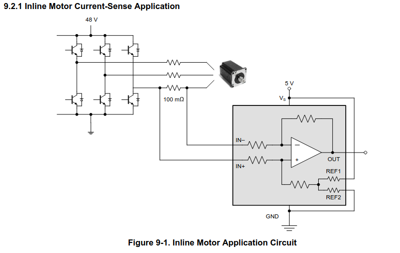 (Bildquelle: https://www.ti.com/lit/ds/symlink/ina241a.pdf) Im Bereich der Spannungsfestigkeit verspricht TI
das Bauteil in Hunderterstückzahlen nach wie vor gute vier Euro kostet. ### STMicroelectronics STM32CubeCLT – Kommandozeilenwerkzeug für IDE-Bauer Mit dem unter https://www.st.com/en/development-tools/stm32cubeclt.html bereitstehenden Paket aus diversen Kommandozeilenutilities möchte STMicroelectronics
Blue data bit 7 29 GND Ground 30 CLK Dot data clock 31 RESETB Active low global reset signal input. 32 HSYNC Horizontal sync input 33 VSYNC Vertical sync input 34 SDI Data input pin in serial interface. 35 SCL Clock input pin in serial interface. 36 GND Ground 37 XR Right side of touch panel. 38 YD Bottom
, die gleich 32Bit-Sekunden zählen, statt im Sexagesimalsystem.
. Der Frequenzausgang des DS3231 lohnt eigentlich nur für Langezeitmessungen wie Stopuhren. Da kann man dann ein paar Stunden mit 1-3PPM auf 32khz schon recht genau messen. Als pures AVR-GCC würde ich auch den Takteingang nehmen
Suspend mode: • All clocks are stopped (except the RTC and memory refresh, which are derived off the 32KHz oscillator without the system PLL’s involvement) • PLLs shut down (programmable option) • The RTC is left running • The DRAM refresh (either CAS before RAS or self refresh) is programmable to be left
- o - 0.01 o O 25 C S 25 C B B I -40 C I 125 C -40 C 0.1 0.001 10 100 1000 10 100 1000 Frequency - kHz Frequency - kHz Figure 4. Boot Voltage Operating Current vs Frequency Figure 5. HB to VSS Operating Current vs Frequency 50 2.0 T = 25 C T = 25 C - e t Rising V o 48 - 1.8 V g D t Rising / o g V t 46
bit(18) 0: off 1: on mdat_polarity_b bit(19) 0: off 1: on sel_nclk_mclk_i_b bit(20) 0: off 1: on 0x05 h dsADC_MCLK_A This register is used to modify Delta Sigma modulator clock. Do not modify if you use internal deltasigmamodulators(Standard use case). dsADC_MCLK_A u32(31:0) dsADC_MCLK_A = (23▯MCLK ) CLK
Charge Current Up to 4A with constant current and constant voltage mode. PWM Switching Frequency: 310KHz In constant voltage mode, the regulation voltage is Can be used as Voltage Source when set by 2 external resistors. The constant charging Battery isAbsent current is programmable with a single current
s i (Large) a a P G −20 −90 R P=0 Ω −40 −180 −610 100 1k 10k 100k 1M 10M 100M Frequency f (Hz) 22 DS04-27204-6E MB3775 Fig. 26 - Ceramic Chip Capacitor (0.1 μF) Temp. characteristic 20 Temp. :Ratio 30°C :0.19 90 ) +25°C :1.0 e 10 +80°C :0.32 ( ) φ B s ( −30°C a A 0 0 P i AV a G +80°C −30°C −10 φ +25
Mit dem DS2423 sollte das möglich sein. Das sind zwei von außen zugängliche 32Bit Zähler drin. Der Baustein selbst wird über 1-Wire angesprochen. Natürlich muß man den Zählereingang entprellen. Schau mal im
geht dieser Impuls verloren. Man muß also jede einzelne Kippwaage zählen. Ich würde das mit einem DS2423 machen. Da jeder dieser IC's 2 unabhängige 32Bit zähler besitzt, kann man immer 2 Messstellen zusammenfassen. Mit dem IC muß halt noch eine kleine Schaltung zum Entprellen mit auf die Platine. Vermutlich
0.5465 - - Fs StopBand Attenuation (Note 13) 50 - - dB - 10.4/Fs - s Group Delay De-emphasis Error Fs = 32 kHz - - +1.5/+0 dB Fs = 44.1 kHz - - +0.05/-0.25 dB Fs = 48 kHz - - -0.2/-0.4 dB Notes: 12. Response is clock dependent and will scale with Fs. Note that the response plots (Figure 38 to Figure 41 on
on a PIC32. "Micromite" on the PIC32MX150/250 "Micromite MkII" on the PIC32MX170/270 "Micromite Plus" on the PIC32MX470 "Micromite Extreme" on the PIC32MZ series "ARMmite H7" on the ArmmiteH7 "ARMmite F407" on
Timing innerhalb der Bitübertragung ohne Delayloops machen können, braucht man mehr als einen Mega32. > Bits zwar aufgrund des 10 kHz RTOS-Ticks mit 100us weiter auseinander > als möglich, aber das stört nicht. Das hatte ich falsch in Erinnerung. Mit Taskwechsel zwischen den Bits kann dort eine
1U 0.8V tAS tAH WR 2.0V 0.8V tW 2.0V D 0D 6 0.8V tDS tDH tCLR tCLRD 2.0V CLR 0.8V Avago Technologies - 9 - HDLx-2416 Series Four Character 5.0 mm (0.2 inch) Smart 5×7 Alphanumeric DisplaysEnlarged Character Data Sheet Font Enlarged Character Font 0.80(
3V L DS012352-25 DS012352-26 DS012352-27 Sourcing Output vs Sinking Output vs Gain and Phase vs Output Voltage Output Voltage Capacitive Load @ 3V DS012352-28 DS012352-29 DS012352-30 Gain and Phase vs Gain and Phase vs @ Capacitive Load 3V Capacitive Load@ 3V DS012352-31 DS012352-32 www.national.com 8 L M C 5V PERFORMANCE 7 1 1 Voltage Noise vs Common Output Voltage vs Offset Voltage vs Common T Mode Voltage @ 5V Input Voltage@ 5V Mode Voltage @ 5V n y DS012352
werden kann. - Hardwareoversampling = 2, 4, 8, 16, 32, 64 ?? - Conversations Rate mit Hardwareoversampling = 500Mhz, 250Mhz, 125Mhz, 62,5kHz, 31,25Khz, 15,625kHz (Aus der Doku: Enabling hardware averaging increases the precision of the ADC at the cost
1/6 der > jeweiligen Samplefrequenz). Vielen Dank für die Info. Bedeutet dies ich kann z.B. 32 Samples mit einer Fs von 40kHz Puffern. Diese Schiebe ich dann durch ein Halbbandfilter und bekomme 16 Samples mit einer neuen Fs2 von 10kHz? Fs = 40kHz -> FsNyquist 20Khz dies durch ein Halband bedeutet
average switching frequency to keep the output voltage in voltage, the frequency will adjust from 32 kHz at light load to regulation. Switching at 25% of the set current limit reduces the 132 kHz at heavy load. The oscillator employes ±5 kHz transformer core flux density significantly. This and the
frequenzunabhängig. Mit 25 ppm geht die Uhr bis zu 15 Sekunden pro Woche falsch, egal ob die Taktquelle 32,768 kHz oder 20 MHz hat. Da scheint es mir wenig sinnvoll, zusätzlich einen präzisen Oszillator mit 32,768 kHz zu verbauen, wenn ich für weniger Geld die Frequenzstabilität des 20-MHz-Quarzes verbessern
Quarz und Oszillator bekannt, habe das nicht durcheinandergeworfen. Ich hätte einen Oszillator mit 32,768 kHz bevorzugt, da kleine Stückzahl und leichter zu integrieren.
Gate Spannung (43mOhm) also einen > Strom von ca. 4,43A ergeben. Bei 100°C hast du aber keinen R_DS(on) von 43mΩ. Auch wenn Fig.6 für U_GS von 10V angegeben ist, dürfte der Faktor für 4.5V Ansteuerung nicht so weit davon entfernt liegen.
erweitert werden, wenn ich wüsste, welche Eingangskapazität mein MOSFET für eine saubere Dimmung von 1.5Khz noch aufweisen darf. Der obige MOSFET hat 255pF und ein Gate-Charge von 4nC bei 10VGS.
Einstellungen für Display und andere, siehe Konstruktor. Als Voreinstellung wird das Display mit 400 kHz betrieben. Allerdings sah der Clock im Oszi eher nach 50 kHz aus, also hattest du das schon geändert?
Einstellungen für Display und andere, siehe > Konstruktor. Als Voreinstellung wird das Display mit 400 kHz betrieben. > Allerdings sah der Clock im Oszi eher nach 50 kHz aus, also hattest du > das schon geändert? Stimmt, dies hatte ich auch so gesehen. Ich hatte diese lib auch teils schon umgeschrieben
kommst auf das ? 08/15 ALPS Poti: https://asset.conrad.com/media10/add/160267/c1/-/en/000442739DS01/datenblatt-442739-alps-rk27112-f25-c0-a203-dreh-potentiometer-staubdicht-stereo-005-w-50-k-1-st.pdf S.3 (40), Resistance taper. > Seriell-parallel-Regler Ah, wieder eine neue Erfindung aus
den Hunni habe ich mir das eigentlich nicht wirklich benötigte Gerät bestellt. Ich habe auch Rigol DS1052, DS1054Z, MSO5074 und DSA815. NÖTIG war das nicht....
fixed frequencies of 1.6 • 1.6-MHz (X Option), 0.6-MHz (Y Option) Switching MHz (X option) and 600 kHz (Y option). Frequency • Low R (DS) DMOS FET The use of SOT-23 package, made possible by the minimal power loss of the internal 1.8-A switch, and • Switch Current Up to 1.8 A use of small inductors and
wird. Bei ATmega328 mit 32 Pins (PLCC) kann aber auch der ADC6 oder ADC7 Pin benutzt werden. Da ein 10:1 Teiler am Eingang benutzt wird, können Spannungen bis zu 50V gemessen werden. Mit einer Erweiterung der Schaltung (DC-DC
til 0,001 mHz (milliHertz). Spændingsmåling på port PC3, hvis den ikke anvendes til seriel output. Ds ATmega328 har 32 ben (PLCC), kan ADC6 eller ADC7 også anvendes. En 10:1 spændingsdeler anvendes, så spændinger op til 50 V kan måles. Med en yderligere DC-DC-konverter, kan zenerdioder også måles. Frekvensgenerering
2 DS1307 64 x 8, Serial, I C Real-Time Clock PIN DESCRIPTION PIN NAME FUNCTION Connections for Standard 32.768kHz Quartz Crystal. The internal oscillator circuitry is 1 X1 designed for operation with a crystal
fixed frequencies of 1.6 • 1.6-MHz (X Option), 0.6-MHz (Y Option) Switching MHz (X option) and 600 kHz (Y option). Frequency • Low R (DS) DMOS FET The use of SOT-23 package, made possible by the minimal power loss of the internal 1.8-A switch, and • Switch Current Up to 1.8 A use of small inductors and
könnte man eventuell die Probeme der aktuellen Class-D Verstärker ausbügeln. Etwa das grausliche 10 kHz Rechtecksignal. In Messungen von Schaltverstärkern schaut ein einfaches 10 kHz Rechtecksignal ohne zusätzlichen Filter "zum fürchten" aus. Ähnlich wie im Bild 13 eines 75000 Euro des Bel Canto Kastens
Jahre Niveau. Jedenfalls kann ich mich noch nicht damit anfreunden das jetzt ein Pilotton bei 450 kHz mit einem halben Volt bis 1 Volt RMS zur HiFi Grundausstattung dazugehört. Aber die Technik verbessert sich ja ständig.
automatically after fault condition is removed 3.8 ~ 4.5V 4.5 ~ 5.3V 5.75 ~ 6.75V 13.8~16.2V 18.8~21.8V 27.6~32.4V 32.9~38.3V 58.4~68V OVER VOLTAGE PROTECTION Protection type : Shut down o/p voltage, re-power on to recover OVER TEMPERATURE Shut down o/p voltage, recovers automatically after temperature goes down
Mismatch vs. Resistor Network 1 R AB (100 k) Mismatch vs. V and Temperature. V and Temperature. DD DD DS22107B-page 32 2008-2013 Microchip Technology Inc. MCP454X/456X/464X/466X Note: Unless otherwise indicated, T = +25°C, V = 5V, V = 0V. A DD SS 4 230 210 3.5 2.7V 5.5V 190 3 ) 170 ) V ( 2.5 ( 150 V O
regulation voltage High PWM Switching Fr equency: is set by the ex ternal res istor d ivider. The 300KHz constant c harging c urrent is pro grammable Constant Charging Voltage Se t By with a single current sense resistor. the External Resistor Divider Deeply discharged batteries are automatically Charging
2 DS1307 64 x 8, Serial, I C Real-Time Clock PIN DESCRIPTION PIN NAME FUNCTION Connections for Standard 32.768kHz Quartz Crystal. The internal oscillator circuitry is 1 X1 designed for operation with a crystal
whenever V CC is between 5.5V and 1.8V. I C operation is not guaranteed when V CCis below 1.8V. The DS1337 maintains the time and date when V CC is as low as 1.3V. OSCILLATOR CIRCUIT The DS1337 uses an external 32.768kHz crystal. The oscillator circuit does not require any external resistors or capacitors
time is usually less than 1 second when using a crystal with the specified characteristics. 9 of 20 2 DS1339 I C Serial Real-Time Clock Table 2. Crystal Specifications* PARAMETER SYMBOL MIN TYP MAX UNITS Nominal Frequency O 32.768 kHz Series Resistance ESR 50 kΩ Load Capacitance C L 6 pF *The crystal, traces
auf den erscheinenden Datenträger kopieren Im MCS Modus meldet sich mein HDS242 übrigens als "GD32 Nand Flash USB Device"
Mikrocontrollern sowie für I2C oder SPI Messungen nehme ich jedenfalls das Rigol Oszi. Mein Tischgerät Rigol DS1104Z Plus ist schon etwas größer und nimmt mehr Platz ein. Mein Messplatz ist im Wohnzimmer. Kurt
Antwort. L. Ja^!ein, je nach Frequeru gemäß IARU-Empfehlungen. -5 - 1 . 2 . 23 W ürden Sie üf ..... kHz ein QS0 in M crsetelegrafie führen? Begründen Sie lhre Antwort. L. Ja^ein, je nach Frequenz gemäß IARU-Empfehlungen. -5 - 1 . 2 . 24 #i:ü:ds:esFif#: ###e3: ..... kHZ in SSB .CQ DX. rufen? L. ::#u:ä,
