-
PDF
HY-SmartSTM32_SCH.pdf
/USART3_TX/TIM2_CH3 PE10/FSMC_D7/TIM1_CH2N 41 FSMC_D7 FSMC_D7 I2C_SDA 48 42 FSMC_D8 I2C_SDA I2S_WS 51 PB11/I2C2_SDA/USART3_RX/TIM2_CH4 PE11/FSMC_D8/TIM1_CH2 43 FSMC_D9 FSMC_D8 I2S_WS I2S_CK 52 PB12/SPI2_NSS/I2S2_WS/I2C2_SMBA/USART3_CK/TIM1_BKIN PE12/FSMC_D9/TIM1_CH3N 44 FSMC_D10 FSMC_D9
in „STM32 can Message“ · Mikrocontroller und Digitale Elektronik ·
-
Datei
main.c
#include "stm32f10x_gpio.h" #include "stm32f10x_rcc.h" #include "stm32f10x_spi.h" #include "stm32f10x_usart.h" #include "system_stm32f10x.h" void SPI_WriteByte(unsigned char ucByte) { while(SPI_I2S_GetFlagStatus(
in „STM32 - USART und SPI“ · Mikrocontroller und Digitale Elektronik ·
-
PDF
en.DM00315319.pdf
6. Figure 6. Example of white LED drive connections VDD= 1.8 V or 3.3 V V DD= 5 V VDD= 1.8 V or 3.3 V VDD= 5 V STM32 STM32 or GPIO1 GPIO GPIO2 MSv46877V1 For the GPIO parallel drive option, open-drain mode must be used and internal pull-up must be disabled. Since
in „STM32: 5 Volt tolerante Eingänge sind es nicht“ · Mikrocontroller und Digitale Elektronik ·
-
Datei
main.c
ENABLE); RNG_Cmd (ENABLE); while (RNG_GetFlagStatus(RNG_FLAG_DRDY) != SET) ; BoardHardwareInit (); STM_EVAL_LEDInit(LED_GRN); STM_EVAL_LEDInit(LED_ORN); STM_EVAL_LEDInit(LED_RED); STM_EVAL_LEDInit(LED_BLU); STM_EVAL_LEDOn (LED_BLU); // Init vom USB-OTG-Port als CDC-Device (Virtueller-ComPort) UB_USB_CDC_Init
in „Controller mit FPU“ · Mikrocontroller und Digitale Elektronik ·
-
Datei
usb_vcp.c
define VCP_STAT_EP 0x83 // for now just use this later set this to 0x85 #define EP0_SIZE 0x40 // can be 8 | 16 | 32 64 #define BULK_SIZE 0x40 // for usb1.1 bulksize always is 64 // The name of the IRQ handler must match startup_stm32.s #define NAME_OF_USB_IRQ_HANDLER USB_IRQHandler #if ENABLE_TRACING #include
in „STM32 USB Übertragungsproblem mit Code von S.F.“ · Mikrocontroller und Digitale Elektronik ·
-
Datei
STM32F4_lcd.c
lcd_zeile1(uint8_t *s) // komplette Zeile ausgeben { lcd_cmd(ZEILE1+1); // 1.Zeile, 1.Spalte lcd_string(s); } void lcd_zeile2(uint8_t *s) // komplette Zeile ausgeben { lcd_cmd(ZEILE2+1); // 2.Zeile, 1.Spalte lcd_string(s); } void lcd_zeile3(uint8_t *s) // komplette Zeile ausgeben { lcd_cmd(ZEILE1+1+PRO_ZEILE); // 3.Zeile, 1.Spalte lcd_string(s); } void lcd_zeile4(uint8_t *s) // komplette Zeile ausgeben { lcd_cmd(ZEILE2
in „Frequenz- und Pulsweitenmessung mit STM32F407“ · Projekte & Code ·
-
Datei
usb_vcp.c
define VCP_STAT_EP 0x83 // for now just use this later set this to 0x85 #define EP0_SIZE 0x40 // can be 8 | 16 | 32 64 #define BULK_SIZE 0x40 // for usb1.1 bulksize always is 64 // The name of the IRQ handler must match startup_stm32.s #define NAME_OF_USB_IRQ_HANDLER USB_LP_CAN_RX0_IRQHandler #if ENABLE_TRACING
in „STM32 USB Übertragungsproblem mit Code von S.F.“ · Mikrocontroller und Digitale Elektronik ·
-
Datei
rs232.txt
#include "stm32h7xx_ll_gpio.h" #include "stm32h7xx_ll_usart.h" #include "stm32h7xx_ll_dma.h" #include "stm32h7xx_ll_tim.h" #include "AllgemeineFunktionen.h" #include "Rs232Kommunikation.h" #include "ModbusRtu.h"
in „STM32H7 USART geht nicht mehr mit Compiler V6.14“ · Mikrocontroller und Digitale Elektronik ·
-
Datei
main.c
configured, this is done through SystemInit() function which is called from startup file (startup_stm32f10x_xx.s) before to branch to application main. To reconfigure the default setting of SystemInit() function, refer to system_stm32f10x.c file */ /* Interrupt Config */ NVIC_Configuration(); /*----
in „STM3210E EVAL SD-Controller SDIO + HiTOP“ · Mikrocontroller und Digitale Elektronik ·
-
PDF
debug_all_demo.pdf
1. Description 1.1. Project Project Name debug_all_demo Board Name debug_all_demo Generated with: STM32CubeMX 4.25.1 Date 11/22/2018 1.2. MCU MCU Series STM32F1 MCU Line STM32F103 MCU name STM32F103C8Tx MCU Package LQFP48 MCU Pin number 48 Page 1 debug_all_demo Project Configuration Report 2. Pinout
in „CubeMX und HAL - I2C hängt sich auf“ · Mikrocontroller und Digitale Elektronik ·
-
Datei
main.c
Timebase.h" #include "UITask.h" #include "MCLibraryISRPriorityConf.h" #include <stdio.h> #include "stm32_eval.h" #if defined USE_STM3210E_EVAL #warning "If using STM3210E-EVAL, please be informed that - on that board - PA6 is shared between TIM8 BKIN and SPI1 MISO, which means that it s not possible
in „STM32F4 - CAN1 empfängt nichts“ · Mikrocontroller und Digitale Elektronik ·
-
PDF
test.pdf
Power Regulation on the Maple Mini for more information. Recommended Reading STMicro documentation for STM32F103CB microcontroller: Datasheet (PDF); covers STM32F103x8, STM32F103xB. Reference Manual RM0008 (PDF); definitive resource for peripherals on the STM32F1 line. Programming Manual PM0056 (PDF); assembly language and register reference. STM32F103CB overview page with links to further references. Footnotes [1] See boardUsedPins for more information. 8 von 8 29.11.2015 20:12
in „Wie kann ich diese Webseite ausdrucken?“ · PC Hard- und Software ·
-
Datei
irmpconfig.h
------------------------------------------------------------------- * Change hardware pin here for STM8 *--------------------------------------------------------------------------------------------------------------------------------------------------- */ #elif defined (SDCC_STM8) // use PA1 as IR input on STM8 # define IRMP_PORT_LETTER A // change here # define IRMP_BIT_NUMBER 1 // change here /*--------------------------------------------------------------------------------------------------------------
in „IRMP - Infrared Multi Protocol Decoder“ · Projekte & Code ·
-
Datei
disco.txt
Mcu.Pin5=PF5 Mcu.Pin50=PE0 Mcu.Pin51=PE1 Mcu.Pin52=VP_SYS_VS_Systick Mcu.Pin6=PC0 Mcu.Pin7=PF11 Mcu.Pin8=PF12 Mcu.Pin9=PF13 Mcu.PinsNb=53 Mcu.UserConstants= Mcu.UserName=STM32F429ZITx MxCube.Version=4.23.0 MxDb.Version=DB.4.0.230 NVIC.BusFault_IRQn=true\:1\:0\:true\:false\:false\:false NVIC.DebugMonitor_IRQn
in „FMC auf STM32F4 konfigurieren?“ · Mikrocontroller und Digitale Elektronik ·
-
 Bild
Bild
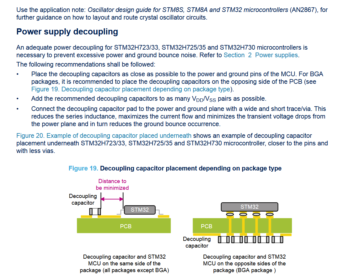
Anleitung zur Entkopplung der Stromversorgung bei STM32 Mikrocontrollern
Use the application note: Oscillator design guide for STM8S, STM8A and STM32 microcontrollers (AN2867), for further guidance on how to layout and route crystal oscillator circuits. Power supply decoupling An adequate power decoupling for STM32H723/33, STM32H725
in „Abblockkondensatoren die 99te“ · Platinen · · Screenshots
-
Datei
Endlosschleife.txt
00061 this is done through SystemInit() function which is called from startup 00062 file (startup_stm32f4xx.s) before to branch to application main. 00063 To reconfigure the default setting of SystemInit() function, refer to 00064 system_stm32f4xx.c file 00065 */ 00066 00067 /* Initialize the LCD */
in „Endlosschleife in RTC Beispiel“ · Mikrocontroller und Digitale Elektronik ·
-
Datei
0001-Add_Frre_Text_Support_To_STM32.patch
----------------------------------------------------------------------------------- + */ +uint_fast8_t +freetext_write_config_to_eeprom (void) +{ + uint_fast8_t rtc = 0; + + if (eeprom_is_up) + { + if (eeprom_write (EEPROM_DATA_OFFSET_FREE_TEXT, (uint8_t *)gfreetext.free_text, EEPROM_DATA_SIZE_FREE_TEXT
-
Datei
irmp-libopencm3.diff
PCM__) || defined(__PCB__) || defined(__PCH__) // CCS PIC compiler # define PIC_CCS +#elif defined(STM32F1) // ARM STM32 with libopencm3 +# define ARM_OPENCM3 +# define F_CPU (SysCtlClockGet()) #elif defined(STM32L1XX_MD) || defined(STM32L1XX_MDP) || defined(STM32L1XX_HD) // ARM STM32 # include <stm32l1xx.h
in „IRMP - Infrared Multi Protocol Decoder“ · Projekte & Code ·
-
Datei
readme.txt
(STM32F105/7 devices), STM322xG-EVAL RevB (STM32F2xx) and STM324xG-EVAL RevB (STM32F4xx) - STM3210C-EVAL Set-up - use CN2 connector to connect the board to a PC host - STM322xG-EVAL Set-up - Use CN8 connector
in „STM32F2 - USB HID“ · Mikrocontroller und Digitale Elektronik ·
-
PDF
DM00027566.pdf
STM32L-DISCOVERY 32L152CDISCOVERY Discovery kits for STM32L151/152 line Data brief Features • STM32L152RBT6 (128 KB Flash memory, 16 KB RAM, 4 KB EEPROM) or STM32L152RCT6 (256 KB Flash memory, 32 KBRAM,
in „SPI-Schnittstelle Befehl: SPI_I2S_SendData(spi2, data)“ · Mikrocontroller und Digitale Elektronik ·
-
PDF
Pinout.pdf
FT I2C1_SCL OSC_OUT 4 NRST I/O RST Device reset input / internal reset output (active low) 5 VDDA S Analog power supply (2) (3)(5) (5) 6 PA0 I/O TTa USART1_CTS , USART2_CTS , USART4_TX ADC_IN0, RTC_TAMP2, WKUP1 7 PA1 I/O TTa USART1_RTS , USART2_RTS (3), EVENTOUT, USART4_RX ADC_IN1 8 PA2 I/O TTa USART1
in „µC für n00bs“ · Mikrocontroller und Digitale Elektronik ·
-
Datei
nrf24l01.c
NRF24L01_PRIM_RX) | (1 << NRF24L01_PWR_UP)); CLEAR_STATUS; CE_HIGH; } /* ------ SPI Low Level: Ein 8 Bit Datenwort senden und holen ------- */ uint8_t __attribute__((optimize(0))) SPI_TransferByte(uint8_t data) { uint8_t val; while(!SPI_I2S_GetFlagStatus(SPI1, SPI_I2S_FLAG_TXE)); // Warte bis TXE (SPI
in „NRF24L01 SPI Problem bringt mich noch zum Wahnsinn!“ · Mikrocontroller und Digitale Elektronik ·
-
PDF
STM32F10xxx__20xxx__21xxx_L1xxxx_Cortex-M3_programming_manual.pdf
1 1 0 0 0 0 1 0 0 0 1 1 0 0 0 1 T E E L E L N E D d S C S C d D A d SCB_ICSR N r S S S S r N VECTPENDING[9:0] B r VECTACTIVE[8:0] 0x04 P e D D D D e P T e I e E E E E e R E e N R P P P P R I R R Reset Valu0 0 0 0 0 0 0 0 0 0 0 0 0 0 0 0 0 0 0 0 0 0 0 0
in „Einstieg in STM32 : STM32F103C8T6 --> Kompilieren und Flashen?“ · Mikrocontroller und Digitale Elektronik ·
-
Datei
miclog.txt
not supported by GDI DiGdiSetConfig(STM8S105C6) chip_config_t::SetCurrentMcu(STM8S105C6) InitDaoAccess() m_sDbFileName = C:\Programme\STMicroelectronics\st_toolset\stvd\swim\config\swim_conf.mdb chip_config_t::TraceDumpContent() m_ConfigAlreadySet
in „STM8S-Testboard“ · Mikrocontroller und Digitale Elektronik ·
-
Datei
stm32f10x.h
(maintained for legacy purpose) */ typedef int32_t s32; typedef int16_t s16; typedef int8_t s8; typedef const int32_t sc32; /*!< Read Only */ typedef const int16_t sc16; /*!< Read Only */ typedef const int8_t sc8; /*!< Read Only */ typedef __IO int32_t
in „STM32 - Eclipse, ARM GCC - Funktionsaufruf geht nicht :-(“ · Mikrocontroller und Digitale Elektronik ·
-
Datei
stm32f10x.h
(maintained for legacy purpose) */ typedef int32_t s32; typedef int16_t s16; typedef int8_t s8; typedef const int32_t sc32; /*!< Read Only */ typedef const int16_t sc16; /*!< Read Only */ typedef const int8_t sc8; /*!< Read Only */ typedef __IO int32_t
in „C-Libs for USB and OLED-Display“ · Mikrocontroller und Digitale Elektronik ·
-
PDF
picomon_v3.pdf
werden folgende Displaycontroller unterstützt: • ILI 9163 • ILI 9340 • ST 7735 / ST 7735R • ST 7789 • S6D02A1 • ILI 9225 Für die Darstellung von Zeichen sind 4 verschiedene Schriftgrößen definiert: • 5x7 Pixel (benötigt zur Darstellung auf dem Display 6x8 Pixel) • 8x8 Pixel • 10x16 Pixel • 12x16 Pixel
in „PicoMon für CH32V003 oder STM32F0xx“ · Projekte & Code ·
-
PDF
ArmAssemblerTutorial.pdf
it is recommended to use the same components. Mikrocontroller selection For the microcontroller, an STM32F103C8 or STM32F103RB by STMicroelectronics will be used. Both controllers are identical except for the flash size (64 KiB vs 128 KiB) and number of pins (48 vs 64). These controllers belong to ST’s
in „ARM-Assembler-Tutorial“ · Mikrocontroller und Digitale Elektronik ·
-
PDF
STM32F407G-DISC1.pdf
OTG micro-AB connector. – 2 USB OTG LEDs LD7 (green) VBUS and To expand the functionality of the LD8 (red) over-current STM32F4DISCOVERY kit with ethernet Two push-buttons (user and reset) connectivity, LCD display and more, visit the USB OTG FS with micro-AB connector www.st.com/stm32f4dis-expansion
in „Neues Projekt - welcher µC?“ · Mikrocontroller und Digitale Elektronik ·
-
PDF
Bauteile.pdf
Kategorie Wert Stück Mouser Mouser Preis LTC1966CMS8#PBF ∆∑ RMS-to-DC Converter 2 584-LTC1966CMS8#PBF 8,93 € IRM-01-3.3S AC/DC Modul 3,3V 300mA (gebraucht) 2 709-IRM01-3.3S 7,79 € LTC4089EDJC-5#PBF Batterie Lade IC 2 584-LTC4089EDJC-5PBF 8,93 € Keystone
in „[V] diverse Bauteile“ · Markt ·
-
Datei
test.cpp
test.cpp * * Created on: 12.08.2013 * Author: Florian */ static void initClock_ext_Oszi() { if (xpcc::stm32::Clock::enableHse(xpcc::stm32::Clock::HSE_BYPASS)) { xpcc::stm32::Clock::enablePll(xpcc::stm32::Clock::PLL_HSE, 8, 336); xpcc::stm32::Clock::switchToPll(); } } MAIN_FUNCTION { initClock_ext_Oszi()
in „I2C-Kommunikation stoppt nach ca. 1-5 Sekunden“ · Mikrocontroller und Digitale Elektronik ·
-
Datei
ws2812_test2.c
--------------------------------------------- ws2812_test.c Programm zum Ansprechen von WS2812 LED's MCU : STM8S103F3 Takt : interner Takt 16 MHz 28.04.2017 R. Seelig ------------------------------------------------------ */ /* ################################################################## STM8S103F3P6
in „SDCC und struct“ · Mikrocontroller und Digitale Elektronik ·
-
Datei
tbasic.c
------------------------------------------------------------------- tbasic.c Basicinterpreter fuer STM8S Controller. Ausgangsdateien von T. Suzuki Modifikationen und Anpassungen an STM8 von R. Seelig "Wettstreit um den billigsten Basic-Computer" Hardware : STM8S103 / S105 19.12.2023 R. Seelig GNU General
-
Datei
STM32_Init.c
/*---------------------------------------------------------------------------- * Name: STM32_Init.c * Purpose: STM32 peripherals initialisation * Version: V1.30 * Note(s): *---------------------------------------------------------------------------- * This file is part of the uVision/ARM
in „ARM STM32 Eingänge werden nicht erkannt“ · Mikrocontroller und Digitale Elektronik ·
-
Datei
STM32_Init.c
/*---------------------------------------------------------------------------- * Name: STM32_Init.c * Purpose: STM32 peripherals initialisation * Version: V1.30 * Note(s): *---------------------------------------------------------------------------- * This file is part of the uVision/ARM
in „ARM STM32 Eingänge werden nicht erkannt“ · Mikrocontroller und Digitale Elektronik ·
-
Datei
stm32_flash.ld
/* * STM32 Discovery Linker Script */ _estack = 0x20002000; /* global needed for startup_stm3210x_md_vl.S */ _minimum_stack_size = 0x100; /* 256 bytes miniumum stack size */ ENTRY(Reset_Handler) MEMORY { rom
in „STM32-Discoveryboard: FTDI Treiber/OpenOCD/Degugging“ · Mikrocontroller und Digitale Elektronik ·
-
Datei
stm32746g_discovery_lcd.c
**** */ /* Includes ------------------------------------------------------------------*/ #include "stm32746g_discovery_lcd.h" #include "fonts.h" #include "font24.c" #include "font20.c" #include "font16.c" #include "font12.c" #include "font8.c" /** @addtogroup BSP * @{ */ /** @addtogroup STM32746G_DISCOVERY
in „STM32F7 Disco und das Display-->hard fault error“ · Mikrocontroller und Digitale Elektronik ·
-
Datei
stm32f30x_gpio.h
GPIO_AF_4 ((uint8_t)0x04) /* I2C1, I2C2, TIM1, TIM8, TIM16, TIM17 */ /** * @brief AF 5 selection */ #define GPIO_AF_5 ((uint8_t)0x05) /* IR_OUT, I2S2, I2S3, SPI1, SPI2, TIM8, USART4, USART5 */ /** * @brief AF 6 selection */ #define GPIO_AF_6 ((uint8_t)0x06) /* IR_OUT, I2S2, I2S3, SPI2, SPI3, TIM1, TIM8 */ /** * @brief AF 7 selection */ #define GPIO_AF_7 ((uint8_t)0x07) /* AOP2_OUT, CAN, COMP3_OUT, COMP5_OUT, COMP6_OUT, USART1, USART2, USART3 */
in „Probleme mit dem STM32F3Discoery, mal wieder.“ · Mikrocontroller und Digitale Elektronik ·
-
Datei
main.c
----- */ #include <stdint.h> /* ------------ Special Include Files --------------- */ #include "tm_stm32f4_ili9341.h" #include "tm_stm32f4_adc.h" #include "tm_stm32f4_exti.h" #include "tm_stm32f4_disco.h" #include "tm_stm32f4_delay.h" #include "tm_stm32f4_low_power.h" #include "tm_stm32f4_nrf24l01_cj.h
in „Organisation der Header und Includes“ · Mikrocontroller und Digitale Elektronik ·
-
PDF
rm0444-stm32g0x1-advanced-armbased-32bit-mcus-stmicroelectronics.pdf
Flash memory (FLASH) 3.7.22 FLASH register map Table 24. FLASH register map and reset values 1 0 9 8 7 6 5 4 3 2 1 0 9 8 7 6 5 4 3 2 0 Offset Register 3 3 2 2 2 2 2 2 2 2 2 2 1 1 1 1 1 1 1 1 1 1 9 8 7 6 5 4 3 2 1 0 N E Y N s s s s s s s s s s s s s W s T s s s s S s N T s s s s s LATENCY FLASH_ACR e
in „Problem mit Clock Configuration beim STM32G031“ · Mikrocontroller und Digitale Elektronik ·
-
Datei
tools.c
stdbool.h> #include <stdint.h> /* --------------- Special Include Files / Librarys ------ */ #include "tm_stm32f4_rtc.h" #include "tm_stm32f4_disco.h" #include "tm_stm32f4_nrf24l01_cj.h" #include "tm_stm32f4_rtc.h" #include "tm_stm32f4_bmp180.h" #include "tm_stm32f4_delay.h" /* -------------- Projekt Include
in „Organisation der Header und Includes“ · Mikrocontroller und Digitale Elektronik ·
-
Datei
spi1.c
-----------------------------------------------*/ #include "stdio.h" #include "stdint.h" #include "stm32f4xx.h" #include "stm32f4xx_gpio.h" #include "stm32f4xx_spi.h" #include "stm32f4xx_rcc.h" #include "stm32f4xx_dma.h" #include "spi1.h" /** @addtogroup SPI1 * @{ */ // these two bytes are dummy bytes
in „STM32 SPI Init“ · Mikrocontroller und Digitale Elektronik ·
-
Datei
system_stm32f7xx.c
startup just after reset and * before branch to main program. This call is made inside * the "startup_stm32f7xx.s" file. * * - SystemCoreClock variable: Contains the core clock (HCLK), it can be used * by the user application to setup the SysTick * timer or configure other parameters. * * - SystemCoreClockUpdate
in „STM32F7 & malloc“ · Mikrocontroller und Digitale Elektronik ·
-
Datei
irmp.c
F_INTERRUPTS * S100_BIT_TIME * MAX_TOLERANCE_05 + 0.5) + 1) #else #define S100_START_BIT_LEN_MIN ((uint_fast8_t)(F_INTERRUPTS * S100_BIT_TIME * MIN_TOLERANCE_10 + 0.5) - 1) #define S100_START_BIT_LEN_MAX ((uint_fast8_t)(F_INTERRUPTS * S100_BIT_TIME * MAX_TOLERANCE_10 + 0.5) + 1) #endif #define S100_BIT_LEN_MIN ((uint_fast8_t)(F_INTERRUPTS * S100_BIT_TIME * MIN_TOLERANCE_10 + 0.5) - 1) #define S100_BIT_LEN_MAX ((uint_fast8_t)(F_INTERRUPTS
in „IRMP - Infrared Multi Protocol Decoder“ · Projekte & Code ·
-
Datei
irmp.c
F_INTERRUPTS * S100_BIT_TIME * MAX_TOLERANCE_05 + 0.5) + 1) #else #define S100_START_BIT_LEN_MIN ((uint_fast8_t)(F_INTERRUPTS * S100_BIT_TIME * MIN_TOLERANCE_10 + 0.5) - 1) #define S100_START_BIT_LEN_MAX ((uint_fast8_t)(F_INTERRUPTS * S100_BIT_TIME * MAX_TOLERANCE_10 + 0.5) + 1) #endif #define S100_BIT_LEN_MIN ((uint_fast8_t)(F_INTERRUPTS * S100_BIT_TIME * MIN_TOLERANCE_10 + 0.5) - 1) #define S100_BIT_LEN_MAX ((uint_fast8_t)(F_INTERRUPTS
in „IRMP - Infrared Multi Protocol Decoder“ · Projekte & Code ·
-
Datei
usb.c
STM32F302, STM32F303xB, STM32F303xBxC) // #define UMEM_SHIFT 1 // #define UMEM_FAKEWIDTH uint32_t // The name of the IRQ handler must match startup_stm32.s #define NAME_OF_USB_IRQ_HANDLER USB_LP_CAN_RX0
in „USB HID Device mit STM32F042“ · Mikrocontroller und Digitale Elektronik ·
-
Datei
st-link_gdbserver_log.txt
031\013\000\010MK\033hLJC\377\001\003\023`\377\377KK\033hJJC\377\377C\023`\377\377GK\033hFJC\377\377S\023`\377\377DK\033hCJC\377\000c\023`z\377@K\033h?JC\377\377c\023`s\377=K\033h<JC\377\000s\023`l\3779K\033h8JC\377\010\003\023`e\3776K\033h5JC\377\004\003\023`^\3772K\033h1JC\377\001\003\023`W\3770K\033h
in „STM32 Cube IDE Inline Assembler“ · Mikrocontroller und Digitale Elektronik ·
-
PDF
STM8_Programming_Manual.pdf
RM0016 Reference manual STM8S series and STM8AF series 8-bit microcontrollers Introduction This reference manual provides complete information for application developers on how to use STM8S and STM8AF series microcontroller memory
in „STLINK V2 und China Boards“ · Mikrocontroller und Digitale Elektronik ·
-
PDF
CMSIS_Doulos_Tutorial.pdf
toggle = Bit_RESET; } elsetoggle = Bit_SET; } } The two listings above show the contents of main.c, and stm32f10x_it.c. This latter file contains interrupt handler templates from ST’s FWLib, which have to be adapted to implement project specific functionality. Example 2 Converting to CMSIS In a second step
in „stm32 tutorial“ · Mikrocontroller und Digitale Elektronik ·
-
Datei
CRC.o.lst
~1\Mubek\LOKALE~1\Temp\ccfS2U7t.s:177 .text._ZN6TZApp4CCrc4crc8EhPhh:00000000 $t C:\DOKUME~1\Mubek\LOKALE~1\Temp\ccfS2U7t.s:182 .text._ZN6TZApp4CCrc4crc8EhPhh:00000000 _ZN6TZApp4CCrc4crc8EhPhh C:\DOKUME~1\Mubek\LOKALE~1\Temp\ccfS2U7t.s:426 .rodata._ZN6TZApp4CCrc10crc8_tableE:00000000 .LANCHOR2 C:\DOKUME~1\Mubek\LOKALE~1\Temp\ccfS2U7t.s:262 .text._ZN6TZApp4CCrc8BlockCrcEPmm:00000000 $t C:\DOKUME~1\Mubek\LOKALE~1\Temp\ccfS2U7t.s:267 .text._ZN6TZApp4CCrc8BlockCrcEPmm
in „Problem mit GCC-Optimierung“ · Mikrocontroller und Digitale Elektronik ·