Configurations Package Type Pin Configurations SOP-8 Pin Description PIN PIN NAME DESCRIPTION 1 BS High-Side Gate Drive Boost Input. BS supplies the drive for the high-side N-Channel DMOS switch. Connect a 0.01µF or greater capacitor from SW to BS to power the high side switch. Input Supply Pin. IN supplies
Set up compressed air connection on the herstellen. Hierzu kann ein handelsüblicher, unit‘s rear side. For this purpose calibrated kalibrierter Schlauch oder auch beigefügter standard hoses or enclosed hose nozzle Schlauchtüllenstecker verwendet werden. connector can be used. Push hose or hose Schlauch
und wie Du diese Anforderungen ermittelt hast. Wie kommst Du auf die 30V? Warum schaltest Du High-Side und nicht Low-Side? "30V mit 1-2A" ist nicht die eigentliche Anwendung. Sondern z.B. "ich möchte mein Terrarium mit einer Heizfolie heizen. Solltemperatur ist xxx, Außentemperatur ist yyy, Heizfolie
Anforderungsliste - insgesamt also: - Schaltung von 30 V Last per 3,3 V IO. - Schaltung erfolgt high-side. - Strom darf nicht in Gegenrichtung fließen (deswegen die "back-to-back" PMOS-Schaltung). - Last ca. 1-2 A dauerhaft, kurzzeitig (kapazitiv) bis 10 A beim einschalten. - Es ist keine galvanischer
Übersicht und dann die Einzelblöche. Von oben nach unten: U1 = TX-Optokoppler (Logik → DMX-ISO-Side) U3 = EN-Optokoppler (Logik → DMX-ISO-Side) U4 = RX-Optokoppler (DMX-ISO-Side → Logik) Hier die Dateierklärungen, hoffentlich macht es die Ansicht einfacher: a: Ausgangsseite b: DC/DC c: Oben
IN nF nF 2.2 k nF 1.2 nF VCO MUTE OFF MHA364 Dimensions in mm. Fig.9 TDA1591 test board (component side). 1996 Sep 02 12 Philips Semiconductors Product specification PLL stereo decoder and noise blanker TDA1591 PACKAGE OUTLINES DIP20: plastic dual in-line package; 20 leads (300 mil) SOT146-1 D M E n l
Typical circuit for use when hot line switching is required. in 1 6 HOT In this circuit the “hot” side of the line is switched and the load connected to the cold or neutral side. The load may be 2 MOC3081–83 5 39 connected to either the neutral or hot line. R inis calculated so thFt I is equal to the
operation where the FB pin receives the amount of current needed to deliver the right power on secondary side. This sequence is shown in Figure 7. Note that during the real starting phase t , sse device consumes some energy from the V DD capacitor, waiting for the auxiliary winding to provide a continuous supply
Vout=V LX=6V 0.5 µA Fosc Oscillation Vout=set 180 kHz Frequency Vout*0.95 Maxdty Duty Ratio on(V “L”)side 84 % LX EFFI Efficiency 85 % ME2108Bxx/Dxx Fosc=180kHz SYMBOL PARAMETER CONDITIONS MIN TYP MAX UNITS V OUT Output Voltage Vout*0.975 Vout Vout*1.025 V V Oscillation IOUT=1mAÿ▯ 0.8 0.9 V start Start-up
VDDP and a 1µF ceramic capacitor from VCC to High-Side Power MOSFET Driver Output. Connect to the high-side ground. N-channel MOSFET gate. VDDP LGATE Linear Regulator Output. VDDP is the output of the 5.2V linear Low-Side Power MOSFET Driver Output. Connect
. 12 REGN Ausgang der internen LDO (typ. 5V, zur Versorgung der Gate-Treiber). 13 LODRV Low-Side Gate-Treiber-Ausgang für den Low-Side MOSFET des Buck-Wandlers. 14 SW Schaltknoten des Buck-Wandlers. 15 HIDRV High-Side Gate-Treiber-Ausgang für den High-Side MOSFET des Buck-Wandlers. 18 VCC
die sind üblicherweise Masseschaltend... Sehr gut. Das bereitet auch weniger Probleme, als high-side-switches. Gruß Jobst
Drehzahlmessung, weil die ja auch Massebezogen ist. KAnn man, muss man aber tricksen... Bei High-Side-PWM geht es aber ganz normal, sofern die Spannung >Umin ist, wo sich der Lüfter normal noch dreht.
batteryzone.de/products/36v-10s-3p-9-6ah-42v-18650-lithium-akku-25a-bms-fur-elektrofahrrader-und-roller?_pos=1&_sid=09ff27466&_ss=r Abmessungen stimmen, 9,6Ah erscheint mir etwas hoch. Aber wenn er 6Ah schafft, ist das auch super... genau wie der Serien-Akku.
SHIELD TAB 0.35 [0.014] drawing for location.) 10.84 [0.427] 2.54 [0.103.20 [0.126] Link LED (Left Side) Activity LED (Right Side) TOLERANCE 6.35 [0.250] .XX+/-0.20[0.008] Color Meaning Color Meaning 11.90 [0.468] DIMS = mm (in) Off No Link Off No Activity Amber 10 Mbps Amber Half-Duplex OEM License Agreement
SHIELD TAB 0.35 [0.014] drawing for location.) 10.84 [0.427] 2.54 [0.103.20 [0.126] Link LED (Left Side) Activity LED (Right Side) TOLERANCE 6.35 [0.250] .XX+/-0.20[0.008] Color Meaning Color Meaning 11.90 [0.468] DIMS = mm (in) Off No Link Off No Activity Amber 10 Mbps Amber Half-Duplex OEM License Agreement
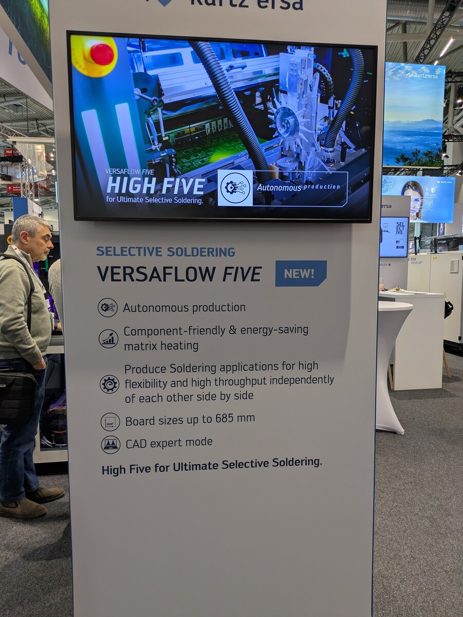
Produce Soldering applications for high flexibility and high throughput independently of each other side by side. Board sizes up to 685 mm. CAD expert mode. High Five for Ultimate Selective Soldering.
useful method is to place the circuit board flat on the surface of the etching solution, with the side to be etched facing downwards towards the etching solution. The circuit board floats easily on top, especially with etching solutions that already have a high density. With this method, the heavier copper chloride (CuCl) sinks to the bottom and fresh copper dichloride (CuCl2) flows in from the sides. This has the same effect as moving the circuit board or the etching bath, but does not require any mechanical movement. The dreaded gas bubbles that form on the circuit board and prevent contact with
measured under board mounted and still air conditions. Symbol Definition Min. Max. Units VB High side floating supply voltage -0.3 625 VS High side floating supply offset voltage VB- 25 VB+ 0.3 V High side floating output voltage V - 0.3 V + 0.3 V HO S B VLO Low side output voltage -0.3 V CC+ 0.3 IOMAX
DFG-Förderung beantragen. Da muss aber trotzdem noch mindestens ein Shunt dran und ob das Teil wirklich High Side messen kann? Ich glaube, für meinen Zweck wird das nicht das Richtige sein. Aber trotzdem danke.
in under 1 Release the right-hand side of the slider in under 1 second whilst still pressing the On sensor 4 second whilst still pressing the On sensor 5 A short flash of all segments 5 A short flash of all segments 6 Press and hold the sensor furthest to the right in under 1 Press and hold the right-hand side of the slider in under second 6 “P” and “0” flash on the displays. The services program 1 second 7 “P” and “0” flash on the displays. The services program has been initiated 7 has been initiated The
Boot-Loop zu sein. Ich würde gerne herausfinden: 1. Was ist das für ein IC (Step-Down? LDO? High-Side-Switch?) 2. Ob es einen kompatiblen Ersatz gibt 3. Welche Spannungen an den Pins anliegen sollten 4. Ob jemand das Pinout oder ein internes Schema des PCM 3 kennt Messungen kann
pull forward will gentle rocking (B) Directional Switch – Lever has eight contact motion from back side of panel easing switch out. positions and will operate in horizontal, vertical, and Install new switch and secure using clip retainer on in four intermediate directions. back side of control panel.
siehe Bilder und hier https://newhavendisplay.com/de/128x64-graphic-cog-lcd-fstn-display-with-white-side-backlight-mounting-holes/ Alles für 8€ + 2,70€ Bücherversand (Versand DHL/Post und Paypal Bei Interesse bitte PM mit Artikelangabe. Danke! MFG Roger
Ergebnis. Kurz zur Schaltung (Basis WS2814F): -Ich gehe davon aus, dass der WS2814F ein Low-Side-Treiber ist und die LEDs über die Kathode ansteuert. (Chinesisches Datenblatt ist sehr schwer zu lesen) -Alle LEDs sind identisch, erhalten aber noch farbspezifische Vorwiderstände zur Strombegrenzung
Nico schrieb im Beitrag #7979684: > -Ich gehe davon aus, dass der WS2814F ein Low-Side-Treiber ist und die > LEDs über die Kathode ansteuert. (Chinesisches Datenblatt ist sehr > schwer zu lesen) Bis auf das Package und den Auxiliary Data Input ist der wie der WS2814 https://www.superlightingled.com
increased by + 0,3 mm. Toroidal tape core with oil and temperature-resistant varnish coat on all sides. = L Die Unrundheit ist in den Durchmessertoleranzen enthalten. The non-circularity is included in the diameter tolerances. For Toroidal tape core, impregnated with a low-contraction impregnation varnish
Shou dig SDB628 PACKAGE DESCRIPTION **Yearweek B 628** TOP VIEW RECOMMENDED LAND PATTERN FRONT VIEW SIDE VIEW DETAIL “A” Figure 4. TSOT23-6/SOT23-6 Physical Dimensions NOTE: 1)ALL DIMENSIONS ARE IN MILLIMETERS. 2) PACKAGE LENGTH DOES NOT INCLUDE MOLD FLASH,PROTRUSION OR GATE BURR. 3) PACKAGE WIDTH DOES
,1 enabling high dynamic range for phased-array systems and dense RF front-ends. On the transmit side, up to sixteen 16 GSPS RF-DACs support output bandwidth up to and beyond 18 GHz, achieving fully symmetric TX/RX operation for multi-channel and multi-mission flexibility. The result: engineers gain
relays, electrovalves,etc. TECHNICAL DATA The instrument is removable from its housing by the front side : is recommended to disconnect the power supply from ELECTRICAL DATA the instrument when it’s necessary to effectuate this Power supply: 12 VDC/VAC, 24, 115, 230 VAC +/- 10% operation. Frequency AC:
of coupling path in degree reference impedance: The port on the same Z 50 Ohm reference impedance side is decoupled, the input power splits according to the coupling factor to the ports on the other side, i.e. power out of the straight port = (1-in·Pd power out of the cross port = k·in with the specified
Hi, ich möchte einen Längsregler bauen mit High-Side N-Mosfet. Regelung soll analog ablaufen (OP). Der Sollwert kommt von einem MCU via DAC (0 bis 3V3). Da der N-Mos High-Side liegt brauche ich eine galvanische Trennung für das Ansteuersignal. Letztendlich
J. schrieb im Beitrag #7964287: > ich möchte einen Längsregler bauen mit High-Side N-Mosfet. Regelung soll > analog ablaufen (OP). Was genau soll das ganze werden? Spannung? Strom? Last? Warum Mosfet und kein NPN oder PNP? > Da der N-Mos High-Side liegt brauche ich eine
camera (model CS165CU, Thorlabs, Newton, NJ, USA). It 2 features 1440 1080 pixels , each having 3.45lm2side length. The total active area is 4.968 3.726mm . Moreover, the camera is able to resolve colors. While this feature is not necessary in principle, it adds instructional value and has proven to be of
zwischen B und C auf dieser 850-EVO-Revision tatsächlich die 5-V-eFuse bzw. ein kompatibler High-Side-Switch, oder ist es ein anderes Power-Bauteil Darf ich für einen kurzen Diagnose-Test die 5 V von SATA P7–P9 direkt an Bauteil B oder einen eindeutig identifizierten VIN-Knoten der eFuse legen, alternativ
zwischen B und C auf dieser 850-EVO-Revision > tatsächlich die 5-V-eFuse bzw. ein kompatibler High-Side-Switch, oder > ist es ein anderes Power-Bauteil TPS62130, Schaltregler.
case, set the CTL pin from “L” to “H”. • Before the battery connection, short-circuit the battery side pins R VDD and R1, shown in the figure in “ Battery Protection IC Connection Example”. • The application conditions for the input voltage, output voltage, and load current should not exceed the package
future. 10 External View & Equivalent Circuit Series Name Dimensions Equivalent Circuit <Top View> <Side View> ① ① Fuse(1) Heater ② SFJ Series ② 3.0 Fuse(2) ③ 4.0 0.85 ③ Unit : mm *NotiThe specification may be subject to change without prior notice in the future. 11 Terminal Size & Reflow Soldering ●Terminal
alter, selten genutzter login hier funktionierte nicht mehr) Situation: Ich suche gerade einen side-assist-Fehler am VW Phaeton. Bekannt ist, daß die Radarsensoren öfter kaputtgehen, wohl öfter der Slave J770 7L6907568D, der Master ist der 7L6907566D, J769. Bei mir wird der Slave als defekt
fallen ja weg. Zum Glück ist ACC nicht betroffen, das ist bei anderen teilweise der Fall, wenn Side Assist defekt ist. Ich habe ohne bisherige Erfahrung mit Cangaroo den CAN-BUS gelesen, kann da aber nichts deuten. Ich möchte eigentlich lieber reparieren, als gebrauchte Sensoren einzubauen,
schrieb im Beitrag #7962796: > Ich habe diese Schaltung bisher nirgends gefunden Ewig alt, high side current sense, mit einem OpAmp wie es der ZXCT1009 tut und MOSFET: [pre] --+---SHUNT----+-- | | 1k | | | +---------+ |
new U matrix, and the matrix equation do not need to be solved again, because only the right-hand side was changed. So altogether this is a quickly done task. This is also true for every further node whose noise voltage should be calculated, because only the right-hand side of step 1 changes, i.e. LU
nun aber nicht der Fall ist. Anhand der Spannungen ist auch klar, warum: Zum einen muss der High-Side MOSFET Q102 von der Controller-PCB aktiviert werden. Zusätzlich müssen die beiden N-Kanal MOSFETs Q100 und Q101 im GND-Zweig eingeschaltet sein. Es wird jedoch nur Q101 angesteuert, Q100 hat 0 V am
recommended nowadays to embed even the standard fonts; you can’t know how it looks exactly at the viewer side unless you embed every font. In this simple file we don’t specify in what way the file should be opened, for instance full screen or clipped. A closer look at the page object no. 2 (/Type/Page) shows
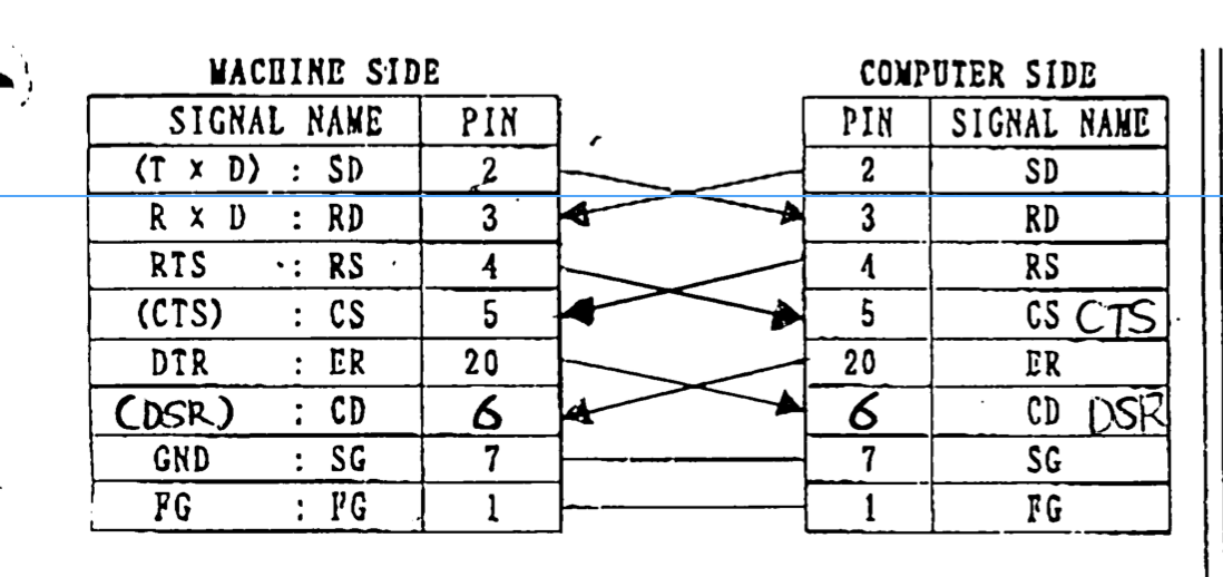
MACHINE SIDE
SIGNAL NAME PIN
(T x D) : SD 2
R x D : RD 3
RTS : RS 4
(CTS) : CS 5
DTR : ER 20
(DSR) : CD 6
GND : SG 7
FG : FG 1
COMPUTER SIDE
PIN SIGNAL NAME
2 SD
3 RD
4 RS
5 CS CTS
20 ER
6 CD DSR
7 SG
1 FG
"nur" der HDMI 1 verabschiedet. Wenn der eingesteckt ist geht er nicht an. Aber HDMI 2 und HDMI side arbeiten noch. So nutze ich jetzt am HDMI side Eingang einen HDMI Switcher. Beim HDMI 1 tippe ich auf sowas wie verbogenen GND Pin der dann beim einstecken kurzgeschlossen wird.
args, **kwargs) self.btn = T.Button(self, text=f'Name_{index}', command=self.onclick) self.btn.pack(side=T.TOP) def onclick(self, event=None): print('%s called on %s'%(event, self.index)) class MainWin(T.Tk): def __init__(self, *args, **kwargs): super().__init__(*args, **kwargs) self.btns = [BtnFrame(self, i, *args, **kwargs) for i in range(5)] for btn in self.btns: btn.pack(side=T.TOP) self.btnExit = T.Button(self, text='Exit', command=self.destroy) self.btnExit.pack(side=T.BOTTOM) if __name__ == '__main__': MainWin().mainloop()
3DRecentlyViewedItemsV2WithMLRPboosterAndUpdatedFeatures_BP&_trksid=p4375194.c102726.m162918 und der IC: power switch high-side 2,6A N-Channel SMD SO8 INFINEON? https://www.ebay.de/itm/297561537649 Wollte mal nachfragen, bevor ich bestelle das es auch die richtigen Teile sind.
Smith chart axis: • The horizontal axis of the Smith chart represents a pure resistor: at the left side, z = 0 (short circuit) and at the right side z = ∞. • The upper section (red part) of the horizontal axis represents impedances with positive imaginary part (series inductor +jx or parallel capacitor
done by inserting a dummy plug into the microphone jack. 8) If you record more than one file on a side, SAVE an empty file named "END" for example, after the last file of interest. If you read this file header, you will know not to search beyond it for files you are seeking. 9) Do not record on the first or last 30 seconds of tape on a side. The tape at the ends gets the most physical abuse. 10) Most cassette recorders have a feature that allows you to protect a cassette from accidental erasure. On the edge of the cassette opposite the
buck regulator, designed to operate from 4.5V to 18V input voltage range. Built-in low R high/low side Power-MOSFETS not only reduce external components and has DS(ON) up to 95% efficiency, ideal for 2A output current applicatiThe EA8252 is designed to take into account the light load mode operation.
for ESR 〔e.g. 9 shows 9m Ω〕 Capacitance Tolerance Packing Orientation 〔M:± 20%〕 R:Cathode on the Side Capacitance (pF) of Sprocket Hole First two digits represent significant figures. Tape width Third digit specifies number of zeros to follow. 〔8:8mm〕 DC rated voltage in volts 〔0E:2.5V〕 Part number

 Bild
Bild
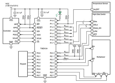
 Bild
Bild

 Bild
Bild

 Bild
Bild