-
Datei
bsp.c
******************************************************* */ static void BSP_InitTickISR (void) { INT32U num; INT32U denom; TCCR0 = 0x0E; /* Set TIMER0 prescaler to CTC Mode, CLK/256 */ TCNT0 = 0; /* Start TCNT at 0 for a new cycle */ num = (INT32U)CPU_CLK_FREQ; denom = 2 * 256 * (INT32U)OS_TICKS_PER_SEC; OCR0 = (INT8U)((2 * num / denom + 1) / 2 - 1); TIFR |= 0x02; /* Clear TIMER0 compare Interrupt Flag */ TIMSK |= 0x02; /* Enable TIMER0 compare Interrupt */ } /* ****************************************************
in „gcc-avr: two or more data types in declaration specifiers“ · Mikrocontroller und Digitale Elektronik ·
-
 Bild
Bild
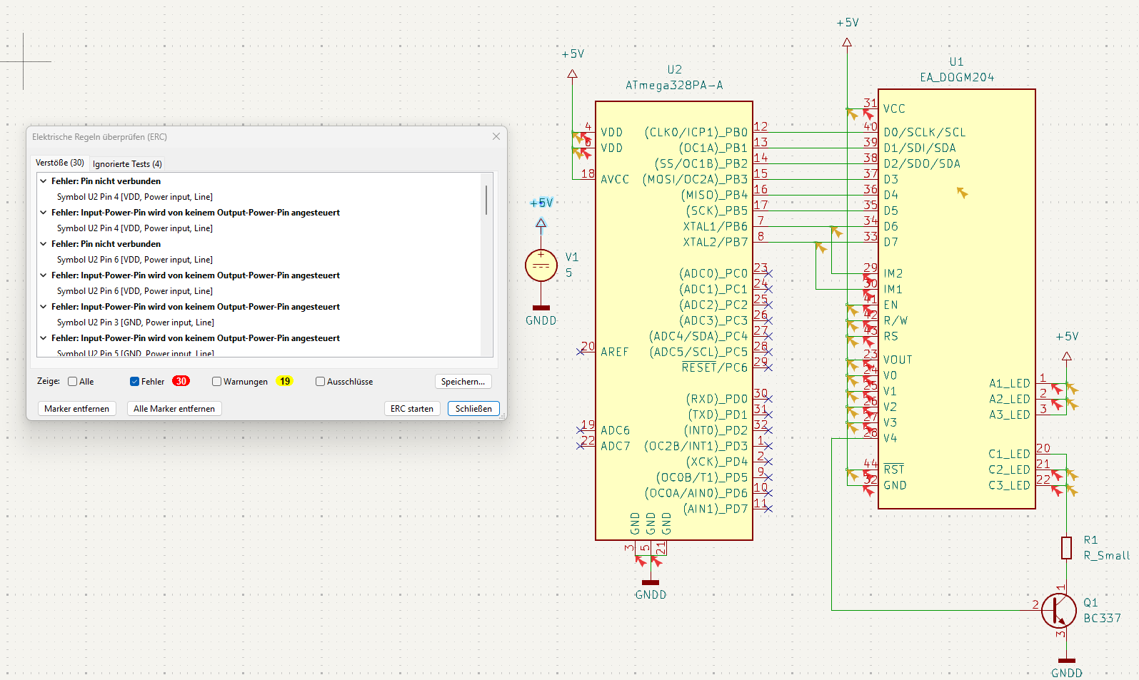
Schaltplan mit Fehlermeldungen aus einer ERC-Prüfung
(ERC) Fehler: Pin nicht verbunden, Input-Power wird von keinem Output-Pin angesteuert, GND, VDD, ATmega32BPA-A, U1 EA_DOGM204, V1 5, GNDD, ADC6, ADC7, U2 ATmega32BPA-A, R1 R_Small, Q1 BC337, A1_LED, A2_LED, A3_LED, C1_LED, C2_LED, C3_LED
in „KiCAD 9.06: ERC mit unberechtigten Fehlern ?“ · Platinen · · Screenshots
-
Datei
timer1.ino
= ripu[ripuM - 1].za32 - ripu[2].za32; avg = avg / (ripuM - 3); sprintf(str, " P %2u auto %1u avg %10ld uspt ", ripuP, autoOn, avg); Serial.print(str); Serial.print(uspt, 6); //sprintf doesn't like floats Serial.print(" clo
in „AVR Timer1 Capture und Overflow gleichzeitig“ · Mikrocontroller und Digitale Elektronik ·
-
PDF
AVR_Z180_CP_M.pdf
1 2 3 4 5 6 A7 74HC00D 5 74HC00D 6 2 SDREQ 74HCT32D 4 3 A IC2B 1 1 R1 A IC2A 3 WE 2 1k GND GND GND IC1A V V U$1G$1 4 IC1B R2 U2 3 3 6 7 XTAL2 VCC_2 5 100n + 13 ST /MREQ 63 5 OE VCC_3 17 60 /HALT /IORQ 62
in „CP/M auf ATmega88“ · Mikrocontroller und Digitale Elektronik ·
-
Datei
gdriver.c
///////////////////////////////////////////////////////////////////////////// void uart1_init (uint32_t baud) { uint32_t fdiv; PCONP |= (1 << 4); // Uart 1 einschalten // Pinsel Bits für UART1 Funktion setzen (Pinsel4 TXD1=1:0 RXD1=2:3 <- 10(0x02) einschreiben) PINSEL4 &= ~((0x03 << 0) | (0x03 << 2)) ; PINSEL4 |= ((0x02 << 0) | (0x02 << 2)); U1IER = 0x00; // Alle IRQ absschalten U1IIR; // IIR ID Register löschen U1RBR; // clear receive register U1LSR; fdiv = (F_apb / 16) / baud; // Baudrate etc einstellen U1LCR = 0x83; // divisor latch
in „Einfacher Low Cost LCD Controller für 320x240 LCD im Textmodus“ · Projekte & Code ·
-
Datei
Achims_I2C.c
} i2c_readNak(); i2c_stop(); } void Ausgabe_Zeile(uint8_t zeile) { uint8_t y; int16_t u; y = 10+10*zeile; // Y Wert für alle Graphikausgaben // Ausgabe des ADC-Werts itoa(adc_werte[zeile-1], Buffer, 10 );
in „PCF 8591 - Hard- und Software“ · Mikrocontroller und Digitale Elektronik ·
-
PDF
adwandler.pdf
Der Analog-Digital-Wandler des ATmega32 Der Analog-Digital-Wandler des Atmega32 arbeitet nach dem Verfahren der sukzessiven Approximation mit einer Auflösung von 10 Bit. Über einen Multiplexer können 8 Spannungsquellen angeschlossen werden
in „ADC initialisieren, Grundlagen“ · Mikrocontroller und Digitale Elektronik ·
-
Datei
main.c
#else lhfe *= M48_RH_RL_RATIO; #endif if(uBE[1]<11) uBE[1] = 11; lhfe /= uBE[1]; hfe[1] = (unsigned int) lhfe; lcd_eep_string(hfestr); //"hFE=" lcd_string(utoa(hfe[1], outval, 10)); SetCursor(2,7); //Cursor auf Zeile 2, Zeichen 7 if(NumOfDiodes
-
PDF
_Dokumentation_V1.2_Stand_29.03.2012.pdf
HI/LO damit das Bitmuster gehalten wird. Danach neues Bitmuster für Säule 9bis 16 ans zweite Latch u.s.w. bis alle 13 Latches gefüllt sind. Die Ebenen werden ja ATMega32 eigentlich durch die Mosfets geschaltet. µC Pinbenutzung: 8 x Datenleitungen für Bitmuster zu denLatches 13 x Latch Enabled 10 x Ebenensteuerungder
in „Tutorial 10x10x10 LED-Cube“ · Mikrocontroller und Digitale Elektronik ·
-
PDF
_Dokumentation_V1.6_Stand_04.08.2012.pdf
HI/LO damit das Bitmuster gehalten wird. Danach neues Bitmuster für Säule 9 bis 16 ans zweite Latch u.s.w. bis alle 13 Latches gefüllt sind. Die Ebenen werden ja ATMega32 eigentlich durch die Mosfets geschaltet. µC Pinbenutzung: 8 x Datenleitungen für Bitmuster zu den Latches 13 x Latch Enabled 10 x
in „Tutorial 10x10x10 LED-Cube“ · Mikrocontroller und Digitale Elektronik ·
-
Datei
PPS5330_hack.c
buf[3]+32); SPI_wr2(buf[1]+32); SPI_wr2(buf[0]+32); } else { SPI_wr2(buf[3]+32); SPI_wr2(buf[2]+32); SPI_wr2(buf[0]+32); SPI_wr2(0x5D); } } void I_measurement () { start_Measurement(I_Mess); uint16_t mess_time
in „PPS5330 Labor-Netzteil hack“ · Mikrocontroller und Digitale Elektronik ·
-
Datei
PPS5330_hack.c
buf[3]+32); SPI_wr2(buf[1]+32); SPI_wr2(buf[0]+32); } else { SPI_wr2(buf[3]+32); SPI_wr2(buf[2]+32); SPI_wr2(buf[0]+32); SPI_wr2(0x5D); } } void I_measurement () { //uint16_t mess_time = ((counter_h << 8) | TCNT0
in „PPS5330 Labor-Netzteil hack“ · Mikrocontroller und Digitale Elektronik ·
-
PDF
AVR042.pdf
voltages do not have internal capacitors (except Atmega162). Note that AT90S8535, Atmega163 and Atmega103 does not have the CKOPT-fuse, instead they have dedicated pins (TOSC1-TOSC2), to connect the 32.768 kHz watch crystal to. Using the clock option that
in „Beschaltung MEGA128 mit ISP und UARD0“ · Mikrocontroller und Digitale Elektronik ·
-
PDF
AVR042.pdf
voltages do not have internal capacitors (except Atmega162). Note that AT90S8535, Atmega163 and Atmega103 does not have the CKOPT-fuse, instead they have dedicated pins (TOSC1-TOSC2), to connect the 32.768 kHz watch crystal to. Using the clock option that
in „Widerstände an MISO und MOSI?“ · Mikrocontroller und Digitale Elektronik ·
-
PDF
doc2521.pdf
voltages do not have internal capacitors (except Atmega162). Note that AT90S8535, Atmega163 and Atmega103 does not have the CKOPT-fuse, instead they have dedicated pins (TOSC1-TOSC2), to connect the 32.768 kHz watch crystal to. Using the clock option that
in „Quarz will nicht anschwingen Atmega8“ · Mikrocontroller und Digitale Elektronik ·
-
PDF
AVR042.pdf
voltages do not have internal capacitors (except Atmega162). Note that AT90S8535, Atmega163 and Atmega103 does not have the CKOPT-fuse, instead they have dedicated pins (TOSC1-TOSC2), to connect the 32.768 kHz watch crystal to. Using the clock option that
in „Mein erstes Projekt“ · Mikrocontroller und Digitale Elektronik ·
-
PDF
AVR042.pdf
voltages do not have internal capacitors (except Atmega162). Note that AT90S8535, Atmega163 and Atmega103 does not have the CKOPT-fuse, instead they have dedicated pins (TOSC1-TOSC2), to connect the 32.768 kHz watch crystal to. Using the clock option that
in „Programier leitungen doppelt nutzen“ · Mikrocontroller und Digitale Elektronik ·
-
PDF
AVR042-doc2521.pdf
voltages do not have internal capacitors (except Atmega162). Note that AT90S8535, Atmega163 and Atmega103 does not have the CKOPT-fuse, instead they have dedicated pins (TOSC1-TOSC2), to connect the 32.768 kHz watch crystal to. Using the clock option that
in „Anfänger: Atmel 8 beschaltung ?“ · Mikrocontroller und Digitale Elektronik ·
-
PDF
Inline_AVR8ASM_arduino.pdf
1: Arbeitsspeicher mit 32 Registern bei den ATmega-MikrocontrTMELDatenblatt AVR Microcontroller 2009] Die Register ab r16 können von jedem sinnvollen Assmeblerbefehl genutzt werden. Um einen Wert in ein solches Arbeitsregister
in „Mit dem ATMEL STUDIO 7 klarkommen“ · Mikrocontroller und Digitale Elektronik ·
-
PDF
assembler_arduino.pdf
1: Arbeitsspeicher mit 32 Registern bei den ATmega-MikrocontrTMELDatenblatt AVR Microcontroller 2009] Die Register ab r16 können von jedem sinnvollen Assmeblerbefehl genutzt werden. Um einen Wert in ein solches Arbeitsregister
in „Arduino Timerprobleme - suche programmierbaren Oszillator“ · Mikrocontroller und Digitale Elektronik ·
-
PDF
AVR_8-bit_AppNote_HardwareDesignConsiderations_AVR042.pdf
voltages do not have internal capacitors (except Atmega162). Note that AT90S8535, Atmega163 and Atmega103 does not have the CKOPT-fuse, instead they have dedicated pins (TOSC1-TOSC2), to connect the 32.768 kHz watch crystal to. Using the clock option that
in „RFM01 Problem“ · Mikrocontroller und Digitale Elektronik ·
-
PDF
IQP_500_GSM.pdf
. Damit diese Baudrate vom Atmega8 mit möglichst keiner Abweichung eingehalten wird, wird ein Oszillator mit einer Frequenz von 11059200 Hz verwendet. Die Abweichung beträgt dann – laut Datenblatt des Atmega8 0,0 % sowohl bei 19,2
in „IQP 500 GSM Bildübertragung Tonerätzverfahren“ · Projekte & Code ·
-
Datei
uart.c
bit */ #ifdef URSEL UCSRC = (1<<URSEL)|(3<<UCSZ0); #else UCSRC = (3<<UCSZ0); #endif #elif defined (ATMEGA_USART0 ) /* Set baud rate */ if ( baudrate & 0x8000 ) { UART0_STATUS = (1<<U2X0); //Enable 2x speed baudrate &= ~0x8000; } UBRR0H = (unsigned char)(baudrate>>8); UBRR0L = (unsigned char) baudrate;
in „SHT11 misst Mist“ · Mikrocontroller und Digitale Elektronik ·
-
Datei
Fehlerhaft1.TXT
KBytes) mtd_dataflash spi0.6: AT45DB642x (8448 KBytes) at_t6816_probe at_t6816 - Using 1 MHz SPI... atmega_probe Atmega168 - Using 1000000 Hz SPI... Atmega168 - Read ID failed, retrying ... Atmega168 - Read ID failed, retrying ... Atmega168 - Read ID failed, retrying ... Atmega168 - Read ID failed, retrying ... Atmega168 - Read ID failed, retrying ... Atmega168 - Read ID failed, retrying ... Atmega168 - Read ID failed, retrying ... Atmega168 - Read ID failed, retrying ... Atmega168 - Read ID failed, retrying ...
in „embedded Linux startet nicht mit bad-blocks (NAND)“ · Mikrocontroller und Digitale Elektronik ·
-
Datei
wiring.c
#endif // busy wait __asm__ __volatile__ ( "1: sbiw %0,1" "\n\t" // 2 cycles "brne 1b" : "=w" (us) : "0" (us) // 2 cycles ); // return = 4 cycles } void init() { // this needs to be called before setup() or some functions won't // work there sei(); // on the ATmega168,
in „Sekunden,Minuten zählen mit der Funktion Millis()“ · Mikrocontroller und Digitale Elektronik ·
-
PDF
wama-online-dokumentation-public.pdf
ARTICLE=9265 L1 0,17 0,17 1SMCC 10µ Induktivitaet http://www.reichelt.de/?ARTICLE=18193 IC1 3,90 3,90 1ATMEGA 32-16 DIP ATmega32 DIL http://www.reichelt.de/?ARTICLE=45026 0,10 0,10 1GS 40 IC-Sockel 40-pol http://www.reichelt.de/?ARTICLE=8224 C6 0,04 0,04 1RAD 105 100/35 Elko 100uF http://www.reichelt.de/?ARTICLE
-
Datei
Unterprogramme.h
and receive complete interrupt */ UART0_CONTROL = _BV(RXCIE)|_BV(RXEN)|_BV(TXEN); #elif defined (ATMEGA_USART) /* Set baud rate */ if ( baudrate & 0x8000 ) { UART0_STATUS = (1<<U2X); //Enable 2x speed baudrate &= ~0x8000; } UBRRH = (unsigned char)(baudrate>>8); UBRRL = (unsigned char) baudrate; /* Enable
in „Roboter-Linienverfolgung mit P-Regler und Ausweichmodus“ · Mikrocontroller und Digitale Elektronik ·
-
PDF
TTester_096k.pdf
P-Channel-Mosfet etc. It was the idea of Markus F. to hand over the work to a AVR microcontroller. 2 Chapter 1 Features 1. One key operation with automatic power shutdown. 2. Battery operation is possible since shutdown current is only about 20nA. 3. Operates with ATmega8, ATmega88, ATmega168 or ATmega328
-
PDF
TTester_096k.pdf
P-Channel-Mosfet etc. It was the idea of Markus F. to hand over the work to a AVR microcontroller. 2 Chapter 1 Features 1. One key operation with automatic power shutdown. 2. Battery operation is possible since shutdown current is only about 20nA. 3. Operates with ATmega8, ATmega88, ATmega168 or ATmega328
-
Datei
releasenotes414rc1.txt
releases. Part support ============ The following new parts have been added to AVR Studio since 4.13 SP2: * ATxmega128A1 * ATxmega64A1 * ATmega32M1 * ATmega32C1 * ATmega32U4 * ATtiny167 * ATtiny88 Check the device matrix in the help system to see which devices are supported by which tools. New Features ============ * Support for the new XMEGA device family in Simulator 2, JTAGICE mkII and STK600. Read more about the new XMEGA family here: http://www.atmel.com/products/AVR/default_xmega.asp * AVR Simulator 2 has been released with complete and accurate simulation of all
in „Honeywell Rondostat HR20E per AVR steuern und konfigurieren“ · Mikrocontroller und Digitale Elektronik ·
-
PDF
3d_drucker_print_v16.pdf
PG0 PH0(RXD2) (WR)PG0 X1-17 10K X1-18 N ATMEGA2560-16AU ATMEGA2560-16AU X1-19 R53 G X1-20 X1-21 +5V 10K X1-22 X1-23 GND X1-24 Z-1 U2 V Z-3 V V V V V 1 3V3 GND3 38 + V X 2 2 2 2 2 2 37 SPI_MOSI + V + + + + + 1 A01
in „Eigenes 3D-Drucker Board - Viele Fragen“ · Mikrocontroller und Digitale Elektronik ·
-
PDF
HEIZUNG_UNGARN.PDF
1 2 3 4 5 6 7 8 A A TXD_MC RXD_MC PD1 P1 D99 R1 100K 1N4148 U3 PD2 P1 U2 CY2 802UIP PI U3101 OSCI VCC PI8U3 08 PI10 PD01 P IU2202 RESIN RST PI U2 06 PY0 PY22 PI U3202 OSCO PI U2 05 PI7U3 07 D10 1N4148 P6 P3 3 RST CLKOUT R66 C3 P IU2 03 CT 32.768KHZ 2K2 100nF P IU2101 REF PY3 PI U3303 INT P3 SCL PI6U3 06 PS14 PS13 P IU2707 CO5 PI PI U3404 PI5U3 05 P6 SEN GND SDA CSW1 402UIP 22pF PI PCF8563/SO08 OC BUT_RESET TLC7705I/SO08 C6 PC1 PT
-
Datei
gdriver.c
///////////////////////////////////////////////////////////////////////////// void uart1_init (uint32_t baud) { uint32_t fdiv; PCONP |= (1 << 4); // Uart 1 einschalten // Pinsel Bits für UART1 Funktion setzen (Pinsel4 TXD1=1:0 RXD1=2:3 <- 10(0x02) einschreiben) PINSEL4 &= ~((0x03 << 0) | (0x03 << 2)) ; PINSEL4 |= ((0x02 << 0) | (0x02 << 2)); U1IER = 0x00; // Alle IRQ absschalten U1IIR; // IIR ID Register löschen U1RBR; // clear receive register U1LSR; fdiv = (F_apb / 16) / baud; // Baudrate etc einstellen U1LCR = 0x83; // divisor latch
in „Grafikfähiger LCD Controller für 320x240 LCD mit 4 Graustufen“ · Projekte & Code ·
-
PDF
ATMEGA128.pdf
P0P1030 PB60PB6 16 P0U1016 P0U1033 33 PG0N0PG0 Vbus0VBUS VCC P0P20331 32 P0P2032 DGND (OC1B)PB6 PG0(/WR) P0P10331 32 P0P1032 7 2 3 HEADER 16X2 B 0 1 D D DGND HEADER 16X2 P D D ) ) VCC ) 3 4 ) ) 2 3 5 1 G P 0 1 T T 4 D 2 2
in „Was nehme ich nur?“ · Offtopic ·
-
Datei
uart.c
and receive complete interrupt */ UART0_CONTROL = _BV(RXCIE)|_BV(RXEN)|_BV(TXEN); #elif defined (ATMEGA_USART) /* Set baud rate */ if ( baudrate & 0x8000 ) { UART0_STATUS = (1<<U2X); //Enable 2x speed baudrate &= ~0x8000; } UBRRH = (unsigned char)(baudrate>>8); UBRRL = (unsigned char) baudrate; /* Enable
in „AVR Bootloader in C, geht mit mega8 nicht“ · Mikrocontroller und Digitale Elektronik ·
-
PDF
Lueftungszentrale.pdf
2 LM3489 D1 C15 2 5 6 R110 7 B RE 2 1 3 HCPL0601 100pF R11 7 8 120R 330R FB2 60V 12k 9 10 Data+ 6 A DE 3 R30 A R32 10k 4U11 IDC-Steckerl. 10pol. 5 GND DI 4 0R C33 GND R111 100nF 8 V+ 2 GND 470R GND_2 VCC
in „Umfrage zu installierten Hausbussen“ · Haus & Smart Home ·
-
Datei
I2Ckpl0.c
int k, char led) { PORTC=led; for (i=0; i<k; i++); PORTC=0xFF; for (i=0; i<k; i++); PORTC=led; } /* 2x grün = 60 255-128-64=60 */ /* 1x orange = 223 255-32=223 */ /* 2x gn+2xrt= 32 */ /* 2. Startsignal und (spätere) Adressierung der PCF's*/ void start(void) { TWCR = (1<<TWINT) | (1<<TWSTA) | (1<<TWEN
in „Wie avr-gcc starten?“ · Mikrocontroller und Digitale Elektronik ·
-
Datei
test_lcd.c
boot test_lcd.elf > test_lcd.lst $ avr-objdump -P mem-usage test_lcd.elf test_lcd.elf: file format elf32-avr AVR Memory Usage ---------------- Device: atmega162 Program: 2512 bytes (15.3% Full) (.text + .data + .rodata + .bootloader) Data: 38 bytes (3.7% Full) (.data + .bss + .noinit) $ avrtest -mmcu=avr5
in „Fehlermeldung: near initialization for“ · Mikrocontroller und Digitale Elektronik ·
-
Datei
pins.h
OCIE3A #define TIMERx_COMPA_vect TIMER3_COMPA_vect // ATmega #define TCCRxA TCCR3A #define COMxA0 COM3A0 #define OCRxA OCR3A #define TCCRxB TCCR3B #define WGMx2 WGM32 #define CSx0 CS30 #else #error TIMER fehlt #endif #define UBRRnL UBRR0L #define UBRRnH UBRR0H #define UCSRnA UCSR0A #define U2Xn U2X0 /* #define USARTn_RX_vect USART0_RX_vect #define USARTn_UDRE_vect USART0_UDRE_vect */ // m1284p // mighty ARDUINO +----\/----+ // RST |1 ISP 36| VCC // RX0 (D 8) PD0 |2 | PB7 (D 7) PWM/SCK #define
in „ATmega328P mit mehr Pins“ · Mikrocontroller und Digitale Elektronik ·
-
PDF
BLDC-_Controller.pdf
1 -VIN 1-VOUT 6 C14 N C15 N C24 DC/DC CONVERTER 7 G 7 G r Art.Nr. 30383. GND 2 r C A GND GND GND Controller PWM Phase U 4 0 4 1 9 + +C16 5 5 N N + + Art.Nr. 810586 u 2 k IR2181 Q1 Q2 1 0 2 0 IRFB3206 IRFB3206 GND L 1 R 1 ATMEGA168-20AU N$51 1 IC5A N$9 R1 3 N$22 N$22 1 8 R27 29
in „BLDC- Controller 44VDC“ · Mikrocontroller und Digitale Elektronik ·
-
Datei
avr_oscilloscope_1_.htm
: 0px" align=justify><B>Programming The ATmega32</B></P> <P style="LINE-HEIGHT: 100%; MARGIN-TOP: 0px; MARGIN-BOTTOM: 0px" align=justify>Burn the ATmega32 with <B>AVR_oscilloscope.hex </B> and select <B>external crystal</B> at the fuses section
in „AVR-OZZI_fuses_help“ · Mikrocontroller und Digitale Elektronik ·
-
Datei
ok2_hynix1.TXT
KBytes) mtd_dataflash spi0.6: AT45DB642x (8448 KBytes) at_t6816_probe at_t6816 - Using 1 MHz SPI... atmega_probe Atmega168 - Using 1000000 Hz SPI... Atmega168 - Read ID failed, retrying ... Atmega168 - Read ID failed, retrying ... Atmega168 - Read ID failed, retrying ... Atmega168 - Read ID failed, retrying ... Atmega168 - Read ID failed, retrying ... Atmega168 - Read ID failed, retrying ... Atmega168 - Read ID failed, retrying ... Atmega168 - Read ID failed, retrying ... Atmega168 - Read ID failed, retrying ...
in „embedded Linux startet nicht mit bad-blocks (NAND)“ · Mikrocontroller und Digitale Elektronik ·
-
PDF
REV4.1_sch.pdf
1 2 3 4 5 6 7 8 R1 不安装 ADS7843/XTP2064 VCC U3 VUSB 0R 1 16 SCK VCC VCC DCLK R8 P1 R3 V5V U? VCC VCC U2 2.8V电源 V28 X+ 2 X+ CS 15 TP_CS VCC 1 3 IN OUT 2 1 VIN OUT 5 R2 Y+ 3 Y+ DIN 14 MOSI 10K 2 0R 1 GND OUT
in „SCCB cameramodul XCLK-Problem“ · Mikrocontroller und Digitale Elektronik ·
-
PDF
fuse_calculator.pdf
settings) can be reviewed and even be set in the last form at the bottom of this page. AVR part name: ATmega32M1 Select (141 parts currently listed) Feature configuration This allows easy configuration of your AVR device. All changes will be applied instantly. Features Ext. Crystal Osc.; Frequency 8.0- MHz;
in „mega32m1 Fuses falsch“ · Mikrocontroller und Digitale Elektronik ·
-
PDF
Protel_Schematic.pdf
1 2 3 4 VCC L1 C5 10uH C6 C9 U1 X1 U2 U3 100nF 100nF 22uF 4 VCCIO TXD 1 D1 Rcv fB 15 Rcv fB 15 D 1 20 5 Input1 3 +IN Input2 3 +IN D VCC RXD D2 Rcv Out 14 Sen1 Rcv Out 14 Sen2 2 GND GND GND 16 USBDM 2 12
in „Spannungsdifferenz Laptop - Veroboard Aufbau“ · Analoge Elektronik und Schaltungstechnik ·
-
PDF
ch32v003_getting_started.pdf
Programmers einen Ardudino UNO / nano oder eines AVR-Systems mit zugänglichen GPIO-Pins und einer USB2UART Bridge. ATmega328, ATmega168, ATmega8 und ATtiny2313 sind in der Lage, die Firmware in den Programmer zu flashen. Übersicht der Schritte zum Aufbau des Selbstbauprogrammers und „erste Schritte“ bei
in „CH32V003: Selbstbauprogrammer und "Getting started"“ · Projekte & Code ·
-
PDF
_Dokumentation_V1.9_Stand_23.09.2013.pdf
HI/LO damit das Bitmuster gehalten wird. Danach neues Bitmuster für Säule 9 bis 16 ans zweite Latch u.s.w. bis alle 13 Latches gefüllt sind. Die Ebenen werden ja ATMega32 eigentlich durch die Mosfets geschaltet. µC Pinbenutzung: 8 x Datenleitungen für Bitmuster zu den Latches 13 x Latch Enabled 10 x
in „Tutorial 10x10x10 LED-Cube“ · Mikrocontroller und Digitale Elektronik ·
-
PDF
_Dokumentation_V1.7_Stand_27.02.2013.pdf
HI/LO damit das Bitmuster gehalten wird. Danach neues Bitmuster für Säule 9 bis 16 ans zweite Latch u.s.w. bis alle 13 Latches gefüllt sind. Die Ebenen werden ja ATMega32 eigentlich durch die Mosfets geschaltet. µC Pinbenutzung: 8 x Datenleitungen für Bitmuster zu den Latches 13 x Latch Enabled 10 x
in „Tutorial 10x10x10 LED-Cube“ · Mikrocontroller und Digitale Elektronik ·
-
PDF
_Dokumentation_V1.8_Stand_27.03.2013.pdf
HI/LO damit das Bitmuster gehalten wird. Danach neues Bitmuster für Säule 9 bis 16 ans zweite Latch u.s.w. bis alle 13 Latches gefüllt sind. Die Ebenen werden ja ATMega32 eigentlich durch die Mosfets geschaltet. µC Pinbenutzung: 8 x Datenleitungen für Bitmuster zu den Latches 13 x Latch Enabled 10 x
in „Tutorial 10x10x10 LED-Cube“ · Mikrocontroller und Digitale Elektronik ·
-
PDF
L-KISS_Schema_v01.pdf
1 2 3 4 5 6 Vcc T3 X7 SCHALT R2 JUMPER 1 2 3 C10 D 5k D U2 U1 100n X3 Vcc FT232R 1 2 3 ATMEGA32 1 PORTA L1 20 1 14 40 GND GND 2 4 VCC TXD PD0 PA0 39 3 1 47u VCCIO 5 15 PA1 38 4 2 16 RXD Vcc PD1 PA2 37 5
in „ATMEGA644 programmieren“ · Mikrocontroller und Digitale Elektronik ·