-
Datei
DABLCD.ino
service].Label); } else { lcd.setCursor(0, 0); lcd.print("No DAB stations "); } } else { char freqstring[32]; if (strlen(fm_ps) == 0) { sprintf(freqstring, "%-8s %3d.%01d", "FM ", fm_freq / 100, (fm_freq % 100) / 10); } else { sprintf(freqstring, "%-8s %3d.%01d", fm_ps, fm_freq / 100, (fm_freq % 100) / 10)
in „DAB Shield Frage zu Arduino Code“ · Mikrocontroller und Digitale Elektronik ·
-
Datei
DABLCD.ino
service].Label); } else { lcd.setCursor(0, 0); lcd.print("No DAB stations "); } } else { char freqstring[32]; if (strlen(fm_ps) == 0) { sprintf(freqstring, "%-8s %3d.%01d", "FM ", fm_freq / 100, (fm_freq % 100) / 10); } else { sprintf(freqstring, "%-8s %3d.%01d", fm_ps, fm_freq / 100, (fm_freq % 100) / 10)
in „DAB Shield Frage zu Arduino Code“ · Mikrocontroller und Digitale Elektronik ·
-
PDF
Private_Entruempelung_des_Bastel-Lagers_V4.pdf
#26 – KFZ FM-T ransmitter • 2 Stück vorhanden • Für den Zigarettenanzünder • Zusammen 5€ #27 – USB MP3 Player • 4 Stück vorhanden • Zusammen 5€ #28 – Arduino MKR 1500 NB • 50€ #29 – Step-Up / Step-Down • Hochwertige Module u.A. von Pololu LT3060 Watterott 5x je 4€ S18V20F5 Pololu#2574 1x je 30€ U1V10F3
-
PDF
Private_Entruempelung_des_Bastel-Lagers.pdf
#26 – KFZ FM-T ransmitter • 2 Stück vorhanden • Für den Zigarettenanzünder • Zusammen 5€ #27 – USB MP3 Player • 4 Stück vorhanden • Zusammen 5€ #28 – Arduino MKR 1500 NB • 50€ #29 – Step-Up / Step-Down • Überwiegend hochwertige Module von Pololu LT3060 Watterott 5x S18V20F5 Pololu#2574 1x U1V10F3 Pololu
-
PDF
Private_Entruempelung_des_Bastel-Lagers_V2.pdf
#26 – KFZ FM-T ransmitter • 2 Stück vorhanden • Für den Zigarettenanzünder • Zusammen 5€ #27 – USB MP3 Player • 4 Stück vorhanden • Zusammen 5€ #28 – Arduino MKR 1500 NB • 50€ #29 – Step-Up / Step-Down • Überwiegend hochwertige Module von Pololu LT3060 Watterott 5x S18V20F5 Pololu#2574 1x U1V10F3 Pololu
-
PDF
Private_Entruempelung_des_Bastel-Lagers_V3.pdf
#26 – KFZ FM-T ransmitter • 2 Stück vorhanden • Für den Zigarettenanzünder • Zusammen 5€ #27 – USB MP3 Player • 4 Stück vorhanden • Zusammen 5€ #28 – Arduino MKR 1500 NB • 50€ #29 – Step-Up / Step-Down • Überwiegend hochwertige Module von Pololu LT3060 Watterott 5x S18V20F5 Pololu#2574 1x U1V10F3 Pololu
-
Bild
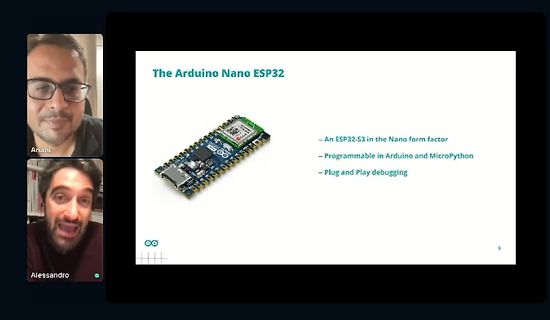
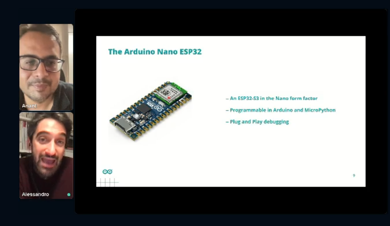
Video-Call mit Präsentation über Arduino Nano ESP32
The Arduino Nano ESP32 An ESP32-S3 in the Nano form factor Programmable in Arduino and MicroPython Plug and Play debugging Anant Alessandro
in „Arduino und Espressif - Neues zum Nano ESP32 und zu MicroPython“ · Mikrocontroller und Digitale Elektronik · · Fotos
-
Bild
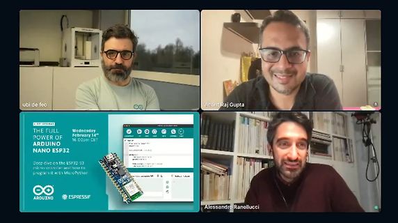
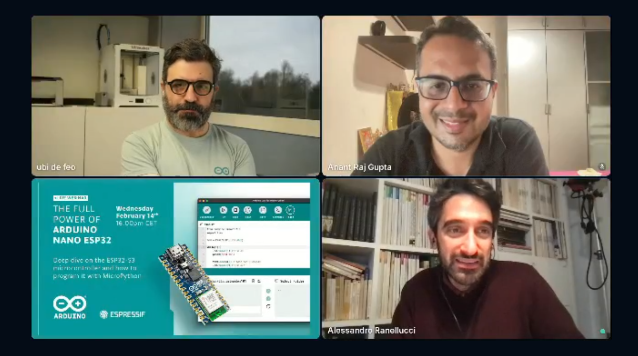
Videokonferenz mit Präsentation eines Arduino Nano ESP32
ubi de feo Anant Raj Gupta THE FULL POWER OF ARDUINO NANO ESP32 Deep dive on the ESP32-S3 microcontroller and learn to program it with MicroPython ARDUINO ESPRESSIF Alessandro Ranellucci
in „Arduino und Espressif - Neues zum Nano ESP32 und zu MicroPython“ · Mikrocontroller und Digitale Elektronik · · Fotos
-
Bild
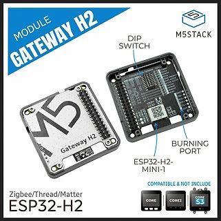
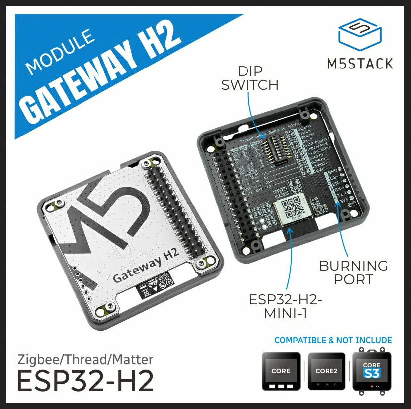
M5Stack Gateway H2 Modul mit ESP32-H2
MODULE GATEWAY H2 M5STACK DIP SWITCH Threadz Gateway M5 H2 ESP32-H2-MINI-1 BURNING PORT Zigbee/Thread/Matter ESP32-H2 CORE CORE2 CORE S3
in „Neue Bauteile: ESP32-C5 in Produktion, spulenloses Relais und neue Mikrocontroller“ · Mikrocontroller und Digitale Elektronik · · Fotos
-
PDF
Last_board_mixed.pdf
/SCK3/PMA1/RB14 1 D- 36 1 kOhm @ 100MHz SPI3_SS_DAC_GROBR815 49,9Ohm 30 AN10/EMDC/AEMDC/RPB15/OCFB/PMA0/RB15 C 1 VUSB3V3 34 L808 VDD / C VBUS 33 R834 K I 0Ohm np L L 2 3 4 5 6 2 3 4 5 / / p S S S S S S S D
in „Schaltplankontrolle Last- + HMI-Board“ · Mikrocontroller und Digitale Elektronik ·
-
PDF
pb_digiconnectme9210-1281450_1_.pdf
aboutthespecificsoftwareplatformcapabilities. WWW.DIGI.COM SPECIFICATIONS Digi Connect ME® 9210 HARDWARE PROCESSORTYPE 32-bit Digi NS9210 processor ARM CORE ARM926EJ-S PROCESSORSPEED 75 MHz CACHE 4k I/D Cache MEMORYBASEPOPULATION Support up to 8 MB NORFlash;Supportupto16MBSDRAM FLEXIBLEINTERFACEMODULES(FIMS) 300 MHz DRPIC165X
in „[V] 18St. DigiConnect ME9210 4/8 Modules for NET+OS (12€ St.)“ · Markt ·
-
PDF
pb_digiconnectme9210-1281450.pdf
aboutthespecificsoftwareplatformcapabilities. WWW.DIGI.COM SPECIFICATIONS Digi Connect ME® 9210 HARDWARE PROCESSORTYPE 32-bit Digi NS9210 processor ARM CORE ARM926EJ-S PROCESSORSPEED 75 MHz CACHE 4k I/D Cache MEMORYBASEPOPULATION Support up to 8 MB NORFlash;Supportupto16MBSDRAM FLEXIBLEINTERFACEMODULES(FIMS) 300 MHz DRPIC165X
in „[V] 2St. neue DIGI-Connect ME Module "Seriell / Lan Umsetzter"“ · Markt ·
-
Datei
PCF8574.cpp
; // removed pre 1.0 support // added begin(dsa, scl) for ESP32 // added reverse() // // 0.1.9 2017-02-27 fix warning about return in readButton8() // 0.1.08 2016-05-20 Merged work of Septillion // Fix/refactor ButtonRead8() - see https://github.com/RobTillaart
in „Fehler bei PCF8574.h Bibliotheke“ · Mikrocontroller und Digitale Elektronik ·
-
PDF
Esp8266-DomoticzAlarm-2B.pdf
CH_12V EN BP CH_C3 21 N CH_C2 GPIO3/RXD CH_C4 JP2 SWITCH_ALARMSTATUS A MIC521G-3.3YM5 2 ADC GPIO4 19 A þÿ4,7µF U2 20 CH_A2 REL1 2 100nF GPIO5 CH_GND GNDD 9 CS0 ESP-12E GPIO12 6 CH_GND GNDD CH_C5 10 7 CH_ALARM_BREAKE_A
in „Zeigt her eure Kunstwerke (ab 2023)“ · Projekte & Code ·
-
Bild
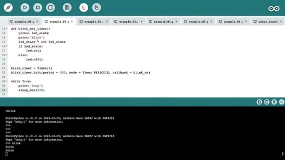
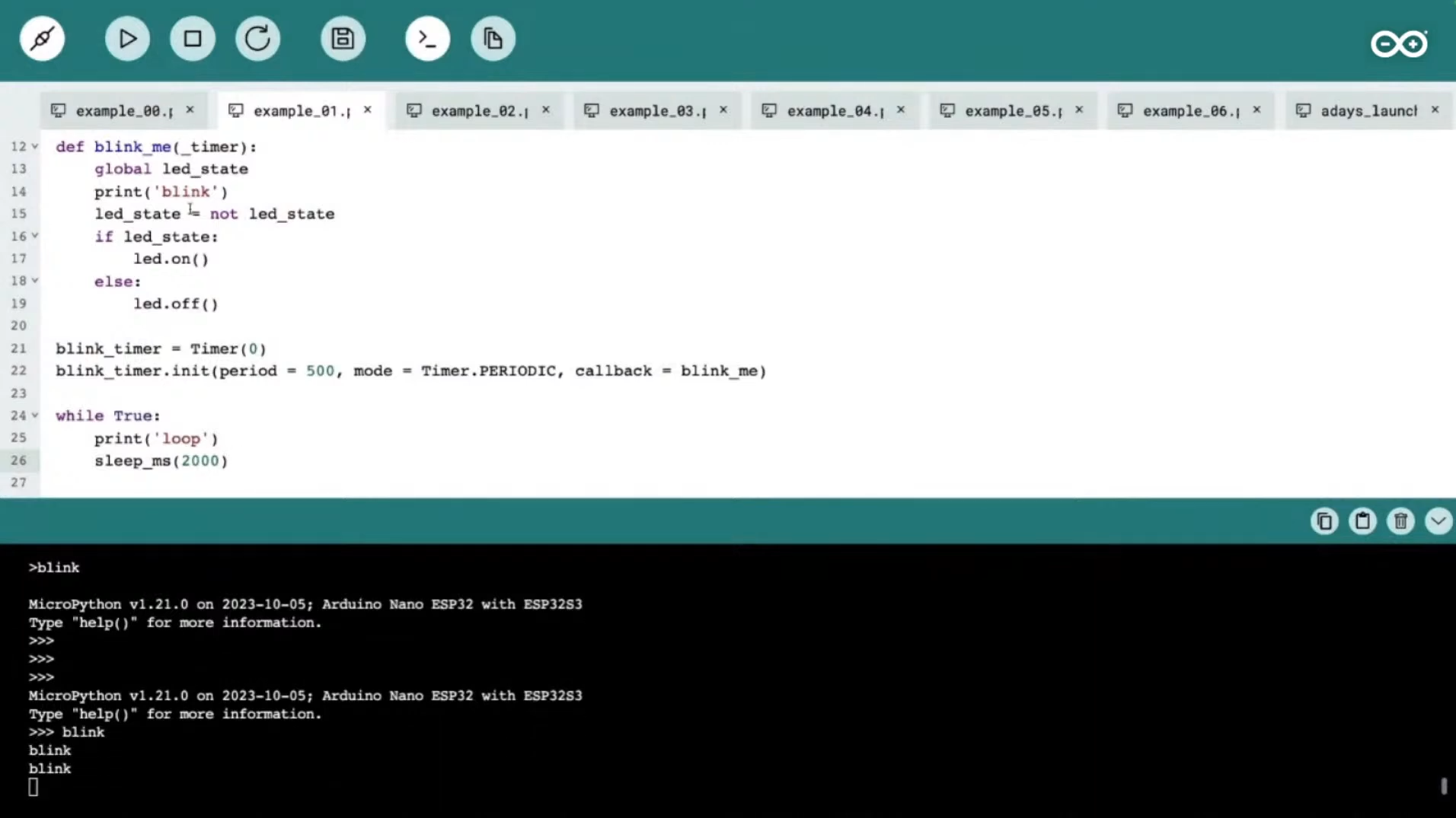
Screenshot eines Code-Editors und einer Python-Konsole
while True: print('loop') sleep_ms(2000) >blink MicroPython v1.21.0 on 2023-10-05; Arduino Nano ESP32 with ESP32S3 Type "help()" for more information. >>>blink blink blink
in „Arduino Days: Neuer Matter-Arduino, Erweiterungen für Arduino-SPS und Cloud“ · Mikrocontroller und Digitale Elektronik · · Screenshots
-
Bild
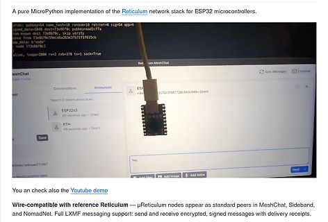
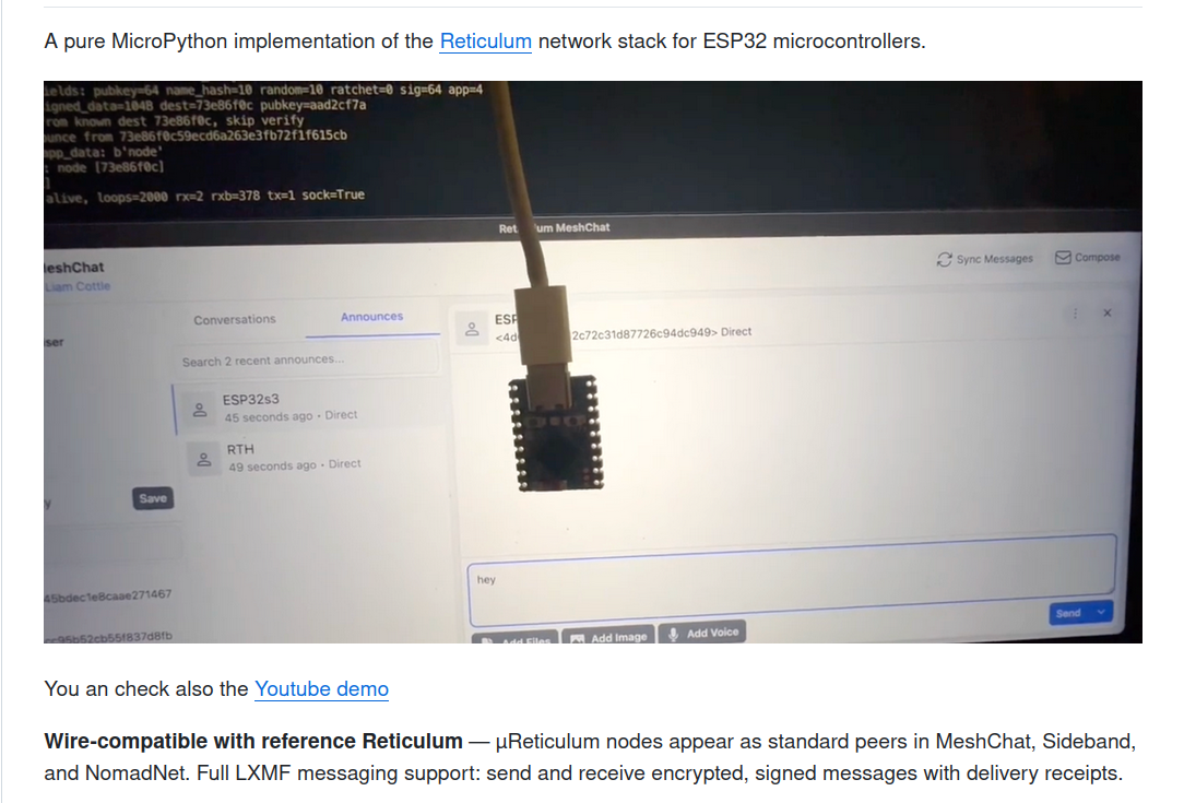
Abfotografierter Bildschirm mit MicroPython Reticulum Implementierung und MeshChat
A pure MicroPython implementation of the Reticulum network stack for ESP32 microcontrollers. fields: pubkey=64 name_hash=10 random=10 ratchet=sig=64 app= signed_data=104 dest=73e86fc0 pubkey=aad2cf7a from=... sig=... skip verify ance from 73e86fc059ecd6b263e5f072f1f615cb
in „Armbian 26.2, preiswerte Rigol-VNAs, Bluetooth und WLAN am Arduino uvam“ · Mikrocontroller und Digitale Elektronik · · Fotos
-
PDF
controller.pdf
P P P P P P P P P P P P P P P P P P P P P P P P P P P P P P P P P P P P P P P 1K5 2 R32 USB_5V 8 8 2 2 5 5 5 5 6 6 6 6 6 6 7 7 7 7 2 2 4 4 4 4 3 3 3 3 3 3 3 3 8 8 8 8 9 9 9 9 9 9 GND 3 K R 3 1 1 1 2 1 1 4 1 1 N 1 3 1 1 X 0 Z Y X e W X I X I X I 2 0 0 X X Y Y Z Z T S E 7 6 5 4 2 _ I E E
in „lpc1768 uart Bootloader funktioniert nicht“ · Mikrocontroller und Digitale Elektronik ·
-
Bild
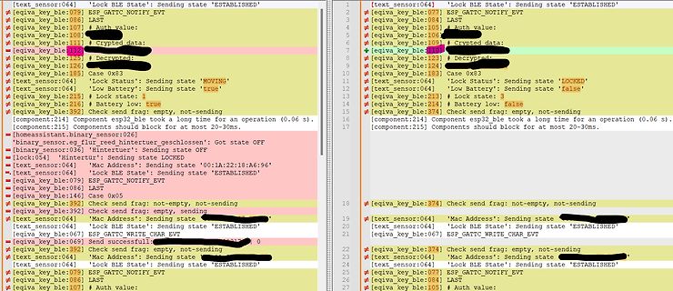
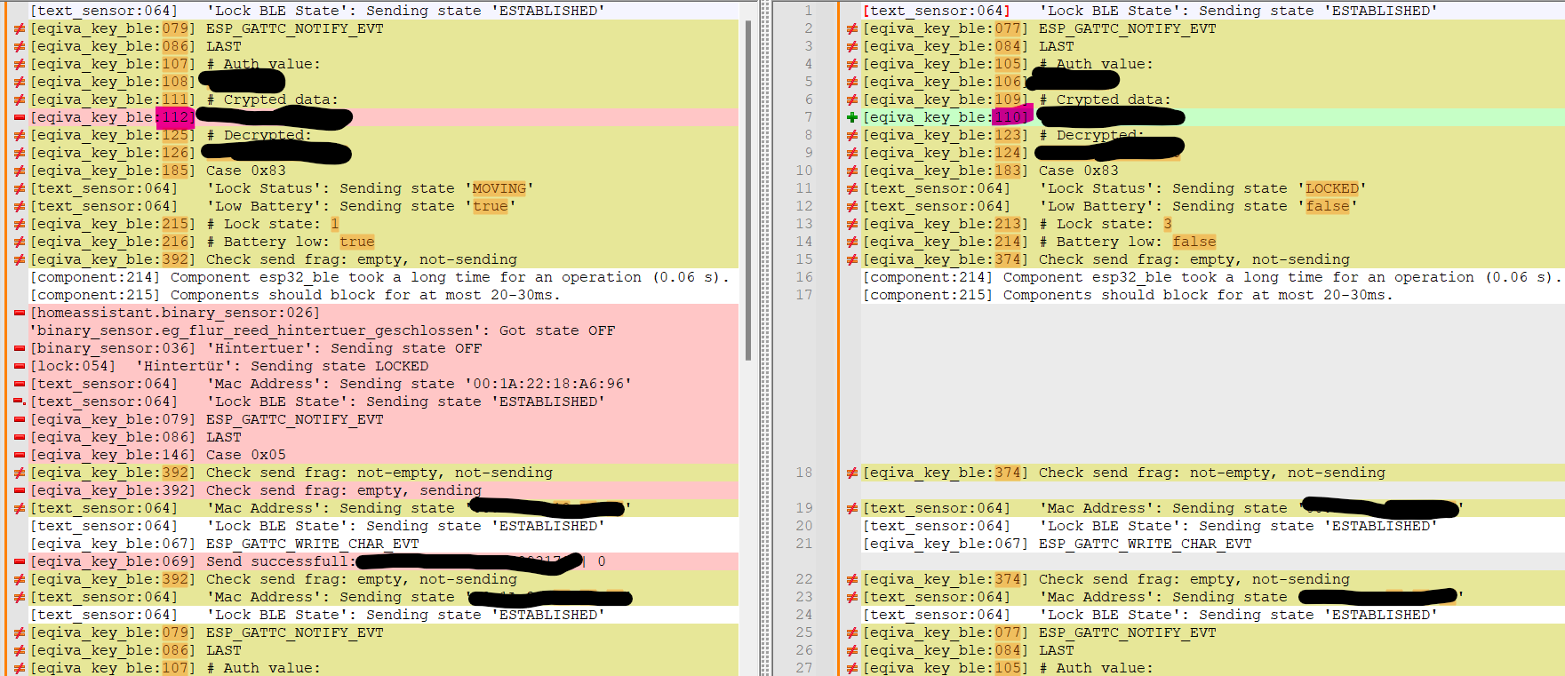
Log-Ausgabe eines Bluetooth-Protokolls
state 'MOVING' [text_sensor:064] 'Low Battery': Sending state 'true' [eqiva_key_ble:215] 'Lock state: 3' [eqiva_key_ble:214] # Battery low: false [eqiva_key_ble:392] Check send frag: empty, not-sending [component:214] Component esp32_ble took a long time for an operation (0.06 s). [component:215] Components
in „Software zum Steuern des Türschlossantrieb "eqiva eQ-3 Bluetooth Smart Lock"“ · Projekte & Code · · Screenshots
-
PDF
LED_Matrix_Controller_V5.pdf
betreibt. Für ein typisches 64x64 LED-Modul werden 6 Schieberegister mit je 64 Bit verwendet. Jeweils 3 für die oberen 32 Reihen und 3 für die unteren 32 Reihen. Jede 3er Gruppe treibt dabei jeweils die roten, grünen und blauen RGB-LEDs an. Die Eingänge der genannten 6 Schieberegister sind an 6 Pins als
in „Universeller 64x64 LED-Matrix Controller“ · Projekte & Code ·
-
PDF
Airframe-Esp32.pdf
1 P N 6 5 D D S I U O K 8 ESP32-S3FN8 P 3.3pF P 3.3pF N A A L _ O O X X M T P D C O 2 2 G D D A A P P 0 0T T M _ T T P D D T T G G U U M P MM G GND GND V V X X 3 C D C V VDD 3V3 CL2 PIIC01 LNA_IN GPIO37 PIC142 ADC Ctrl
in „CP2102 ESP32-S3 USB Verbindung“ · Mikrocontroller und Digitale Elektronik ·
-
Datei
SPI_Interrupt_UDP_Beta.ino
--------------END REGISTER SETTINGS ---------------------*/ // Initialize serial interface #ifndef ESP8266 while (!Serial); // for Leonardo/Micro/Zero #endif Serial.println("Accelerometer Test"); Serial.println(""); // Set Wifi values Serial.printf("Connecting to %s ", ssid); WiFi.begin(ssid, password
in „ADXL345 und ESP8266: Echtzeitdatenergassung mit konstanter Abtastrate und Interrupts“ · Mikrocontroller und Digitale Elektronik ·
-
PDF
pb_digiconnectme9210.pdf
aboutthespecificsoftwareplatformcapabilities. WWW.DIGI.COM SPECIFICATIONS DigiConnectME®9210 HARDWARE PROCESSORTYPE 32-bit Digi NS9210 processor ARM CORE ARM926EJ-S PROCESSORSPEED 75 MHz CACHE 4k I/D Cache MEMORYBASEPOPULATION Support up to 8 MB NORFlash;Supportupto16MBSDRAM FLEXIBLEINTERFACEMODULES(FIMS) 300 MHz DRPIC165X
in „V] 2St. DIGI-Connect ME Module "Seriell TTL RS232 / LAN Umsetzter"“ · Markt ·
-
Datei
wetter.ino
#include "main.h" #include <ArduinoJson.h> #include <ESP8266WiFi.h> #include <pgmspace.h> #include <stdio.h> #include <String.h> #include <stdint.h> const String HFc = "2"; // Forecast = (Hfc-1) * 3h const int HFcN = 2; // Muss identisch sein mit dem String
-
PDF
D_Vivaro_TD_Kap_4.pdf
i k 5 4 5 3 2 8 6 5 8 5 4 h l S i c r . e a i . u b g r . 8 0 3 1 3 7 7 9 4 0 2 i i f n k 3 3 4 2 1 6 4 3 6 4 3 e m e E s v c u n e r r A 0 A A A A A A A A A A r e h k 4 3 5 2 1 8 5 4 7 4 3 r L i b h S i s r h b b i . A A A A i e g e . 2 4 6 3 A 2 5 7 7 9 1 m h r n k 3 2 3 1 5 6 3 2 5 2 2 o v E L L L n R R R R R R R s u s C D s + C D s + C D s + C D A a B A + B e A + B e A + B e A + s A a A a A a A B B B e 9 E 1 1 E t h S A L A S A T A L A
in „Wie wird eine zweite Batterie eingebaut?“ · Fahrzeugelektronik ·
-
Datei
memcopy2.py
print(f'alloc: {ticks_diff(t1,t0):6} µs') # alloc: 2286 µs print(f'BYTE: {td2:6} µs {SIZE/td2:6.1f} MB/s') # BYTE: 25019 µs 9.6 MB/s print(f'HALF: {td3:6} µs {SIZE/td3:6.1f} MB/s') # HALF: 13508 µs 17.8 MB/s print(f'WORD: {td4:6} µs {SIZE/td4:6.1f} MB/s') # WORD: 6758 µs 35.5 MB/s # print(f'WORDasm:{td5:6} µs {SIZE/td5:6.1f} MB/s') # WORDasm: 1772 µs 187.8 MB/s cpufreq(normfreq) test()
-
Datei
espLogger.ino
CONTENT=\"noindex,nofollow\"><link rel=\"icon\" href=\"/favicon.ico\" type=\"image/x-icon\"><TITLE>ESP32 Log</TITLE></HEAD><BODY><P>"); line_t* ptr = root; uint_fast8_t firstline_flag = 1U; char puffer[128]; uint8_t* cp; uint32_t cctr; receive(); Serial.println("Seitenabruf"); while (NULL != ptr) { receive
in „Fehlersuche ESP32, der mit Hilfe der Arduino IDE programmiert wurd“ · Mikrocontroller und Digitale Elektronik ·
-
Bild
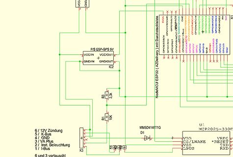
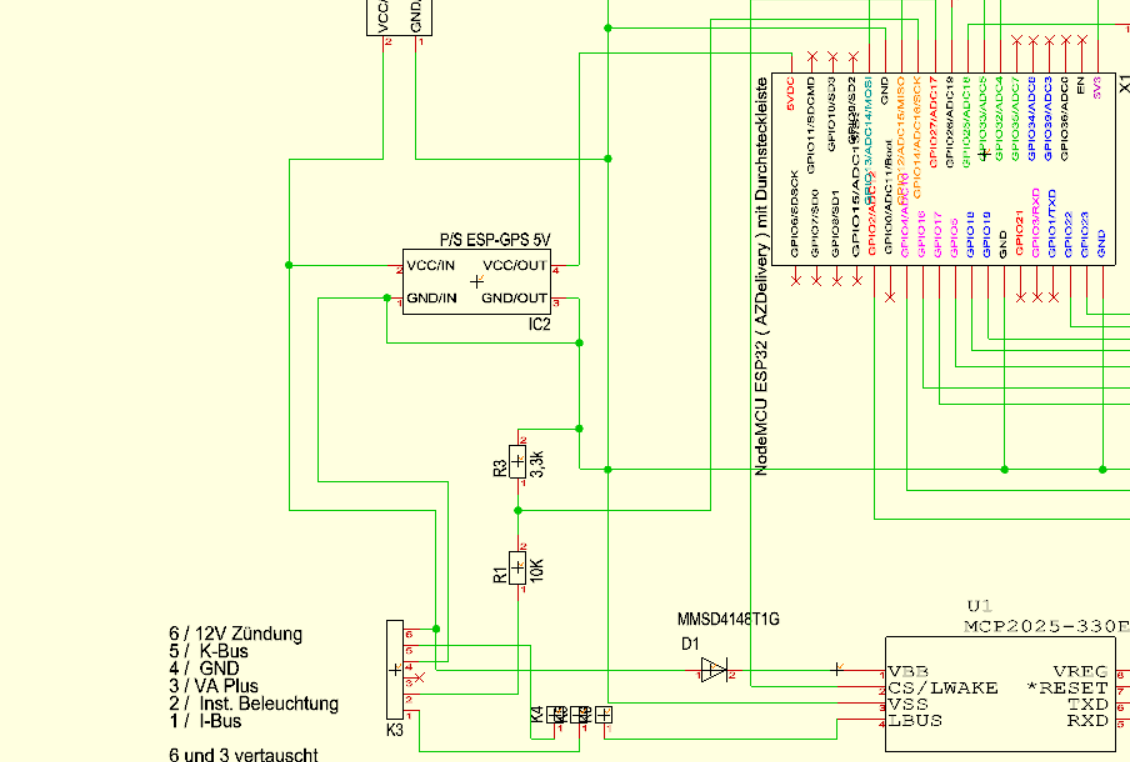
Schaltplan mit NodeMCU ESP32 und GPS Modul
VCC GND P/S ESP-GPS 5V VCC/IN VCC/OUT GND/IN GND/OUT IC2 NodeMCU ESP32 (AZDelivery) mit Durchsteckleiste GPIO6/SD, GPIO7/U0TXD, GPIO10/U0RXD, GPIO11/SD, GPIO12/SD, GPIO13/SD, GPIO14/SD, GPIO15/SD, GPIO16/RXD, GPIO17/TXD, GPIO18, GPIO19, GPIO21, GPIO22, GPIO23, GND, 5V1, 3.3k, 10K, 6/12V Zündung, 5/ K-Bus, 4/ GND, 3/ VA Plus, 2/ Inst. Beleuchtung, 1/ I-Bus, K3, MMSD4148T1G, D1, U1, MCP2025-330F, VBB, CS/LWAKE, RESET, VSS, TXD, LBUS, RXD
in „ESP32 und einfacher spannungsteiler“ · Mikrocontroller und Digitale Elektronik · · Schaltpläne
-
PDF
iot.pdf
Q1 S8050 R2 A D DTR 1 B C 3 EN . . VDD33 12k 2 E _ _ C A D 3 A-GNDA 3 Q4 A-GNDD + S8050 A RTS 12k 1 3 IO0 A N 2 B C N G 3 GND R14 E G A 0,1uF k C A R 1 C43 0,1uF VDD3V3 0,1uF C52 IC1 N N ESP32-WROOM-32D__
in „Schaltung des IOT-Steckdoses mit Eagle entwickeln“ · Mikrocontroller und Digitale Elektronik ·
-
PDF
raffstorecontrol.pdf
1 2 3 4 5 6 Input 24V Display und Steuerung U5 - PullUps ESP intern ULN2803A - Logik high mit 24V 128x64px C4 3 10 SDA 1 SSD1315 3 COM SCL 2 1,3 inch OLED 100nF 1 I1 O1 18 1 GND J5 U9 2 17 2 3 Conn_01x04 GND
in „mcp23017 pull up / Vorwiderstand erforderlich?“ · Mikrocontroller und Digitale Elektronik ·
-
Datei
main.c
manipulation, while the slower digits calculation is only done once per change. */ #include "Arduino.h" // esp32c3, ACM-native usb, usb_cdc enabled uint8_t seg[10]={0x3F,0x06,0x5B,0x4F,0x66,0x6D,0x7D,0x07,0x7F,0x6F}; // 7 segment font uint8_t clo[25]={0,1,0,2,0,3,4,1,2,3,3,4,4,4,2,1,3,4,0,1,2,3,2,1,0}; // charlieplex lowpin uint8_t chi[25]={1,0,2,0,3,0,0,2,1,2,1,1,2,3,3,3,5,5,5,5,5,4,4,4,4}; // .. and highpin hw_timer_t *t=NULL;int32_t b,port; // buffers nstuff uint8_t i,s,pin[6]={4,5,6,7,20,21}; // *** CHANGE THIS *** // display io pins void set
in „fumot 12.000-Puffs Einweg-Vape mit LED-Display“ · Offtopic ·
-
Datei
Wall-E_ESP8266_v1.15.ino
boolean DebugOn = false; const char* ssid1 = "ssid1"; const char* ssid2 = "ssid2"; const char* ssid3 = "ssid3"; const char* password = "password"; ESP8266WiFiMulti wifiMulti; const char* host = "wall-e"; const String noResponse = "no response"; ESP8266WebServer server(80); ESP8266HTTPUpdateServer httpUpdater
in „Automower G3 mit USB Diagnoseport fernsteuern?“ · Mikrocontroller und Digitale Elektronik ·
-
Datei
Wall-E_ESP8266_v1.14.ino
[type=submit], input[type=reset], button {"; s += " -webkit-appearance: none;"; s += " background-color: #303031;"; s += " border: 1px solid #404040;"; s += " color: white;"; s += " font-size: 20px;"; s += " padding: 16px 32px;"; s += " text-decoration
in „Automower G3 mit USB Diagnoseport fernsteuern?“ · Mikrocontroller und Digitale Elektronik ·
-
Bild
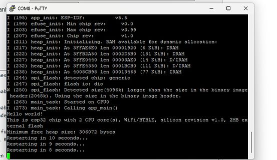
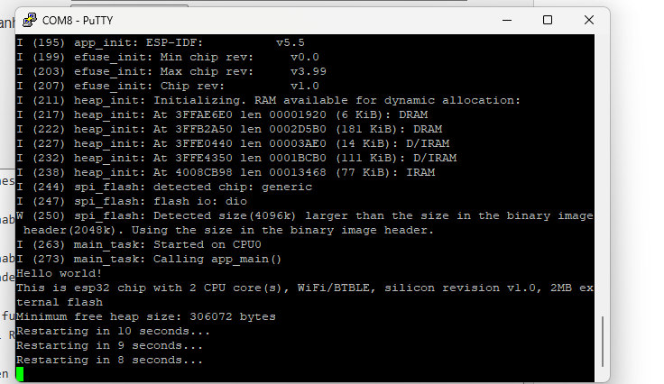
PuTTY Terminal Ausgabe ESP-IDF Bootvorgang
COM8 - PuTTY I (195) app_init: ESP-IDF: v5.5 I (199) efuse_init: Min chip rev: v0.0 I (203) efuse_init: Max chip rev: v3.99 I (207) efuse_init: Chip rev: v1.0 I (211) heap_init: Initializing. RAM available for dynamic allocation: I (
in „Keine Kommunikation zu esp32 möglich“ · Mikrocontroller und Digitale Elektronik · · Screenshots
-
Datei
irmpconfig.h
------------------------------------------------------------------------------------ * Change IRMP_32_BIT here * * Normally, IRMP_32_BIT ist 0. Then we use irmp.command as a 16 bit value. * If you set IRMP_32_BIT to 1, we will use irmp.command as a 32 bit value. * A 32 bit command costs more CPU resources
in „IRMP - Infrared Multi Protocol Decoder“ · Projekte & Code ·
-
PDF
raffstorecontrol.pdf
1 2 3 4 5 6 Input GND Display und Steuerung U5 - PullUps ESP intern ULN2803A - Logik high mit 24V 128x64px C4 3 10 Q1 SDA 1 SSD1315 3 COM 2N7002 SCL 2 1,3 inch OLED 100nF 1 I1 O1 18 1 GND J5 U9 2 17 2 2 3
in „mcp23017 pull up / Vorwiderstand erforderlich?“ · Mikrocontroller und Digitale Elektronik ·
-
Datei
Solar_v2.5_OTA_ext_LOLIN.ino
content_strings3[10] = iap_buf.substring(16, 32) ; // len = 16 holds: date & time content_strings3[10].setCharAt(4, '/') ; // change single signs content_strings3[10].setCharAt(7, '/') ; content_strings3[10].setCharAt
in „Unerwartet Kompilierungsfehler ESP8266 / Funkwetteranzeige treibt mich in den Wahnsinn“ · Mikrocontroller und Digitale Elektronik ·
-
PDF
Schematic_Aktor_Steuerung_2020-07-13_19-22-06.pdf
+3.3V +3.3V +5V R6 ESP32-WROOM-32DC CN1 10k XH-5A_C26521 3 5 LED4 LED3 LED2 LED1 D 4 VCC WS2812B WS2812B WS2812B WS2812B N SDA 3 SDA 1 4 1 4 1 4 1 4 C37 1 G 38 SCL 2 SCL 2VDD DIN 3 2 VDD DIN 3 2 VDD DIN
in „Schaltplan kontrolle“ · Mikrocontroller und Digitale Elektronik ·
-
Datei
irmpconfig.h
------ * Hardware pin for ARM STM32 (HAL) - don't change here, define IRMP_RECEIVE_GPIO_Port & IRMP_RECEIVE_PIN in STM32Cube (Main.h) *--------------------------------------------------------------------------------------------------------------------------------------------------- */ #elif defined (ARM_STM32_HAL) // STM32: IRMP_RECEIVE_GPIO_Port & IRMP_RECEIVE_PIN must be defined in STM32Cube # define IRMP_PORT_LETTER IRMP_Receive_GPIO_Port # define IRMP_BIT_NUMBER IRMP_Receive_Pin /*--------------------
in „IRMP - Infrared Multi Protocol Decoder“ · Projekte & Code ·
-
Datei
LOADER.HTM
Protected-mode <ul> <li>CS: set to 8 (2nd GDT entry) with access to the whole 4GB range (base=0, limit=4GB, 32-bit code)</li> <li>DS, ES, SS: set to 16 (3rd GDT entry) with access to the whole 4GB range (base=0, limit=4GB, 32-bit data)</li> <li>ESP: set to the top of 640KB (ESP=000A0000h),</li> <li>EIP: set according
in „Pollin Netbox“ · Mikrocontroller und Digitale Elektronik ·
-
Bild
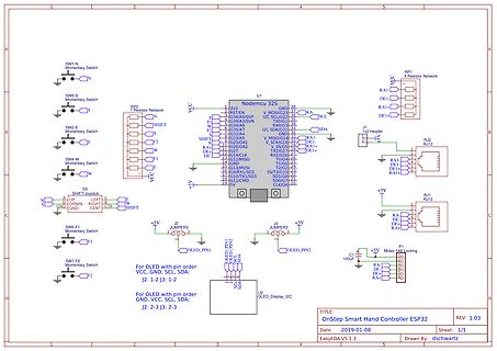
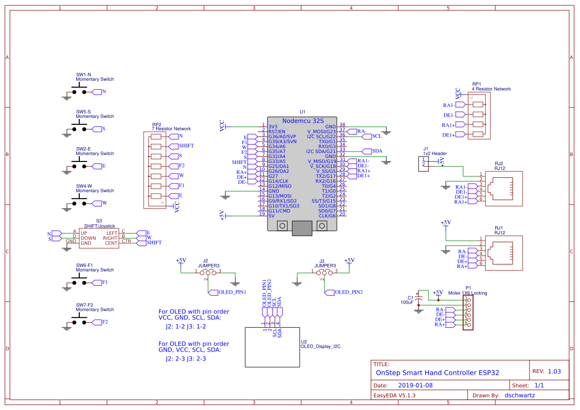
Schaltplan eines OnStep Smart Hand Controllers ESP32
SW1-N Momentary Switch, SW5-S Momentary Switch, SW2-E Momentary Switch, SW4-W Momentary Switch, S3 Joystick, SW6-F1 Momentary Switch, SW7-F2 Momentary Switch, RP2 Resistor Network, U1 NodeMCU 32S, J2 JUMPER3, J3 JUMPER3, U2 OLED_Display_I2C, RP1 4 Resistor Network, RJ2, RJ1, F1, C1 100uF, TITLE: OnStep Smart Hand Controller ESP32, Date: 2019-01-08, REV: 1.03, Drawn By: dschwartz, EasyDA V5.1.3
in „Labornetzteil vs Batterie“ · Mikrocontroller und Digitale Elektronik · · Schaltpläne
-
Bild
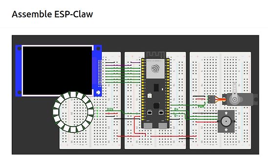
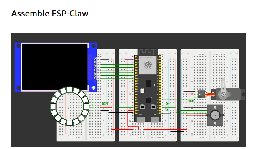
Virtueller Aufbau eines ESP-Claw mit Breadboards
Assemble ESP-Claw ESP32-S3 WROOM-1 DIN D+ D- PWM
in „Raspberry Pi CM0 bei AliExpress, STMicroelectronics mit PX5, neue Messtechnik und AI-Assistenten“ · Mikrocontroller und Digitale Elektronik · · Screenshots
-
Datei
SPI_Interrupt.ino
+++++ //+++++++++++++++++++++++++++++++++++++++++++++++++++ // Initialize serial interface #ifndef ESP8266 while (!Serial); #endif Serial.begin(2500000); Serial.println("Accelerometer Test"); Serial.println(""); // Set Wifi values Serial.printf("Connecting to %s ", ssid); WiFi.begin(ssid, password);
in „ADXL345 und ESP8266: Echtzeitdatenergassung mit konstanter Abtastrate und Interrupts“ · Mikrocontroller und Digitale Elektronik ·
-
PDF
esp8266player2-sch.pdf
C IC10 C TVDD $ $ RESET RESET TX GND T P P C4 ADC RX GND 10*2 TVSS D D S CH_PD GPIO4 CS_RFID 5 GND AUX1 19 0E 1 E R TOUCH_INT GPIO16 GPIO5 CS_TOUCH C 1 I2C AUX2 20 6P 6 P $ $ SCK GPIO14 GPIO0 GLOBAL_RST GND 32 EA EO E O P P MISO GPIO12 GPIO2 CS_MEM OSCOUT 22 Q1 L T L T GPIO13
-
PDF
Schematic.pdf
LNA_IN GND 0▯' C22 C23 7 6 5 4 3 2 1 0 9 8 7 6 5 4 3 TBD TBD 5 5 5 5 5 5 5 5 4 4 4 4 4 4 4 U32 P _ _ P N 4 4 DD S D U O K 3 E A A L L I I RT T T C T T I GND GND D D T T P P 0U M M 3 M M P V V X X G G U P G D 1 D LNA_IN LNA_IN GPIO37
-
PDF
211101-Espressif_ESP32_Schema.pdf
3.5 Peripherais and Sensors 3 F U N C T I O N A L D E S O R P T I O N 3.5.2 Peripheral Schematics V D D 3 3 V D D 3 3 9 9 C1 l O u F |.GND C 2 0 . 1 u F R I ■Ü N U G N D U A R T D O W N L O A D 1 0 K U l 1 )1 I G N D G N D 3 0 2 3 7 1023 CO C 3 3 3 V 3 1 0 2 3 3 6 C N GND.| 0.1 uF ..EN 1022 SENSOR VP 4 1 0 2 2 3 5 T X D SENSOR_VP T X D O |iGND S E N S O R V N 5 R X D O 3 4 R X D 1 0 3 4 6 SENSOR_VN 3 3 1021 1034 1021 1 0
in „ESP32 MicroPython Brownout detector was triggered“ · Mikrocontroller und Digitale Elektronik ·
-
Bild
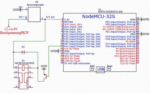
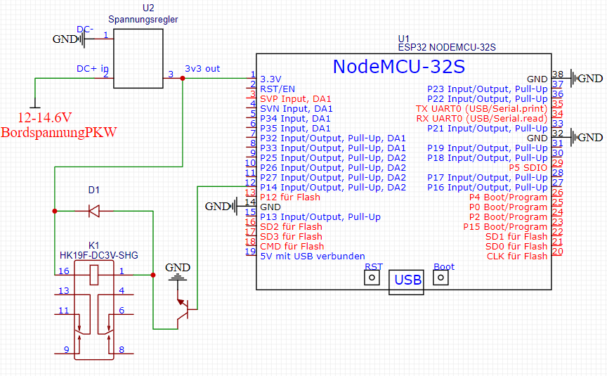
Schaltplan mit ESP32 NodeMCU und Relais
U2 Spannungsregler GND DC+ in 3v3 out 3,3V RST/EN SVP Input, DA1 SVN Input, DA1 P34 Input, DA1 P35 Input, DA1 P32 Input/Output, Pull-Up, DA1 P33 Input/Output, Pull-Up, DA1 P25 Input/Output, Pull-Up, DA2 P26 Input/Output, Pull-Up, DA2
in „ESP32 im PKW an Spannungsteiler Relais schalten“ · Analoge Elektronik und Schaltungstechnik · · Schaltpläne
-
PDF
Baubeschreibung_1.0.pdf
die Verluste durch die doch höheren Ströme zu hoch. Aus den 5V werden über einen Linearregler die 3.3V abgeleitet. Da die 3.3V nur minimal belastet werden, sind die Verluste gering und kein Kühlkörper erforderlich. Microcontroller ESP32 WROOM mit 18 IO-Pins und zwei AD-Pins. Zwei Schrittmotortreiber
in „Schachbrettposition Erkennung“ · Mikrocontroller und Digitale Elektronik ·
-
PDF
Firework_Peri_Mainboard.pdf
3 ON_ARMED_MODE R14 GND R26 D O O E 1 4K7 5 M D S CH4- 14 GND 100K S ON_SAFE_MODE 3 C7 U5 GND 4K7 GND _ M V 13 N u OKI-78SR-5_1.5-W36h-C +5V R20 E _ CH4+ - 2 1 0 l 3 M F GND 9 Adr0 CH3- 12 GND F J2 1 n

in „Again: ESP32 external Power funktioniert nicht“ · Mikrocontroller und Digitale Elektronik ·
-
PDF
REV12schoen.pdf
A 4 K L MINUS48 M GND2 0 4 1 I/O1 I/O5 6 S GND C13 IC4 1 0 C14 2 I/O2 I/O6 7 3 ICSPWM L 3 C1206C104M5RAC ESP32-WROOM-32D_(8MB) W 1 C1206C104M5RAC 3 GND I/O7 8 3 3,3öP I 3 1 2 V+ C W 1 2 4 I/O3 I/O8 9 + A + GND2 1 GND_1 SD0 21 7 R 2 C GND 5 I/
in „Probleme mit Konstantstromtreiber / gatetreiber“ · Analoge Elektronik und Schaltungstechnik ·
-
PDF
JuCanSchematic.pdf
7 IO35 IO21 26 +VOUT LED2 IO32 GND2 GND GND LED3 8 IO33 IO19 27 SPI_MISO LED1 9 IO25 IO18 28 SPI_SCK 10 IO26 IO5 29 SPI_CS 11 IO27 IO17 30 SPI_INT 5 + C4 12 IO14 IO16 31 + 13 32 10uF GND 14 IO12 IO4 33 15 GND1 IO0 34 16 IO13 IO2 35 17 SD2 IO15 36 T_DATA GND TP2 TP1 SD3 SD1 18 CMD SD0 37 +5V 19 EXT_5V CLK 38 ESP32-DEVKITC-32D Header: 691313510004 Plug: 691351500004 CAN_P 1 1 CAN_N 2 2 GND 3 3 IC3 VIN 4 4 GND TJA1050T-CM/118 J1 1 8 N CAN_P 691313510004 2 TXD S 7 G JP2