-
PDF
ATMega16.pdf
bi-directional counter unit. Figure 41 shows a block diagram of the counter and its surroundings. 88 ATmega16(L) 2466E–AVR–10/02 ATmega16(L) Figure 41. Counter Unit Block Diagram DATA BUS (8-bit) (Int.Req.) TEMP (8-bit) Clock Select Count Detector Tn TCNTnH (8-bit) TCNTnL (8-bit) Clear Control Logicn TCNTn
in „DCF auf INT0“ · Mikrocontroller und Digitale Elektronik ·
-
Datei
stk500boot.c
__) #define SIGNATURE_BYTES 0x1E9306 #elif defined (__AVR_ATmega8535__) #define SIGNATURE_BYTES 0x1E9308 #elif defined (__AVR_ATmega162__) #define SIGNATURE_BYTES 0x1E9404 #else #error "no signature definition for MCU available" #endif #if defined(__AVR_ATmega8__) || defined(__AVR_ATmega16__) || defined(__AVR_ATmega32__) \ || defined(__AVR_ATmega8515__) || defined(__AVR_ATmega8535__) \ /* ATMega8 with one USART */ #define UART_BAUD_RATE_LOW UBRRL #define UART_CONTROL_REG UCSRB #define
in „STK500v2-Bootloader von Peter Fleury“ · Projekte & Code ·
-
PDF
_ATmega32.pdf
1 0.0% 1 -7.8% 3 -7.8% 0.5M – – 0 -7.8% – – 0 0.0% 0 -7.8% 1 -7.8% 1M – – – – – – – – – – 0 -7.8% Max (1) 230.4 kbps 460.8 kbps 250 kbps 0.5 Mbps 460.8 kbps 921.6 kbps 1. UBRR = 0, Error = 0.0% 164 ATmega32(L) 2503C–AVR
in „Anschwingvorgang µC & Quarz“ · Mikrocontroller und Digitale Elektronik ·
-
PDF
Amadeus.pdf
Tested - High-voltage serial programming ATtiny12 Tested - High-voltage serial programming only ATmega48 Not Tested* ATmega8 Not Tested* ATmega88 Not Tested* ATmega8515 Not Tested ATmega8535 Not Tested ATmega16 Not Tested ATmega162 Not Tested ATmega168 Not Tested* ATmega169 Not Tested ATmega32 Not Tested
in „USB-Programmer PIC/AVR Jetzt auch auf Deutsch :-)“ · Mikrocontroller und Digitale Elektronik ·
-
PDF
GPS_Datenlogger.pdf
GPS-Maus auf die Unterseite gelegt (Abbildung 7) und der weiße Folienkleber entfernt (vgl. Abbildung 8). Abbildung 7: RGM-2000 Unterseite Abbildung 8: RGM-2000 ohne Folienkleber 9 Man erkennt (vgl. Abbildung 8) vier Haltemagnete und zwei Schrauben. Die Schrauben werden nun mit einem Schraubendreher (z
in „GPS Datenlogger Eigenbau Montageanleitung“ · Projekte & Code ·
-
Datei
Arduino.h
AVR_ATtiny45__) || defined(__AVR_ATtiny85__) #define DEFAULT 0 #define EXTERNAL 4 #define INTERNAL1V1 8 #define INTERNAL INTERNAL1V1 #define INTERNAL2V56 9 #define INTERNAL2V56_EXTCAP 13 #else #if defined(__AVR_ATmega1280__) || defined(__AVR_ATmega2560__) || defined(__AVR_ATmega1284__) || defined(__AVR_ATmega1284P
in „Sekunden,Minuten zählen mit der Funktion Millis()“ · Mikrocontroller und Digitale Elektronik ·
-
PDF
ATT5FCA9.pdf
ATmega48 ATmega169 STK502 ATmega3290 STK504 ATtiny12 AT90S1200 ATmega64 STK501 ATmega169P STK502 ATmega6450 STK504 ATtiny13 AT90S2313 ATmega88 ATmega323 ATmega6490 STK504 ATtiny15 AT90S2323 ATmega103 STK501
in „Angebot STK500+STK501+JTAGICE“ · Mikrocontroller und Digitale Elektronik ·
-
Datei
log.txt
141291], GMP version 5.0.1, MPFR version 3.0.0-p8, MPC version 0.8.2 GGC heuristics: --param ggc-min-expand=30 --param ggc-min-heapsize=4096 Compiler executable checksum: 3b5c1459ff36aeee3e399eb7528509d4 COLLECT_GCC_OPTIONS='-w' '-O2' '-flto' '-D' 'STACK_SIZE=2048' '-D' 'NO_TRAMPOLINES' '-D' 'SIGNAL_SUPPRESS' '-mmcu=atmega128' '-I' '/home/georg/gnu/install/gcc-4.7/avr/include' '-v' '-save-temps' /local/gnu/install/gcc-4.7/lib/gcc/avr/4.7.0/../../../../avr/bin/as -mmcu=atmega128 -o 980709-1.o 980709-1.s COMPILER_PATH=
in „avr-libc: relocation truncated to fit“ · Mikrocontroller und Digitale Elektronik ·
-
PDF
Rollladensteuerung.pdf
densteuerung konsequent über I2C-Portexpander vom Typ MCP23017 erfolgen. Im ersten Ansatz wurde daher ein Atmega168 gewählt. Im Einsatzfall sind maximal 8 Rollläden zu steuern. Der mechanische Aufwand ließ sich beim Einsatz eines Atmega16 besser gestalten, wobei die Aktoren anstelle MCP23017 über inte- grierte
-
Datei
yaap.ini
AT90S1200 Dev2=ATtiny12 Dev3=ATtiny15 ;Dev4=ATtiny22 Dev5=AT90S2313 Dev6=AT90S2323 Dev7=AT90S2333 Dev8=AT90S2343 Dev9=AT90S4414 Dev10=AT90S4433 Dev11=AT90S4434 Dev12=AT90S8515 Dev13=AT90S8535 Dev14=ATmega103 Dev15=ATmega103_Old Dev16=ATmega161 Dev17=ATmega162 Dev18=ATmega163 Dev19=ATtiny26L Dev20=ATmega8515 Dev21=ATmega8 Dev22=ATmega32 Dev23=ATmega16 Dev24=ATmega128 [Fuses] A=CKSEL0 B=CKSEL1 C=CKSEL2 D=CKSEL3 E=BODEN F=BODLEVEL(0) G=SPIEN H=BOOTRST I=BOOTSZ0 J=BOOTSZ1 K=SUT0 L=SUT1 M=ESAVE N=CKOPT O=PLLCK P=RSTDISBL
in „Problem: ATMega16 und YAAP“ · Mikrocontroller und Digitale Elektronik ·
-
PDF
Rollladensteuerung.pdf
1-aus-2 Auswahl des Zielprozessors getroffen: MCU_TARGET = atmega16 #MCU_TARGET = atmega168pa Mit Auswahl des atmega168pa wird automatisch die Generiervariante eingestellt, wonach die Relais über MCP23017 angesteuert werden. 8.2 Setzen der RV3029 EEPROM Funktionsbits
-
PDF
AVRISPmkII_UG.pdf
prompt the user to upgrade AVRISP mkII The following devices are supported: Tiny Mega Other ATtiny12 ATmega48 AT86RF401 ATtiny13 ATmega8 AT89S51 ATtiny15 ATmega88 AT89S52 ATtiny22 ATmega8515 AT90PWM2 ATiny2313 ATmega8535 AT90PWM3 ATtiny24 ATmega16 AT90CAN32 ATtiny26 ATmega162 AT90CAN128 ATtiny45 ATmega165
in „AVRISP mkII - 10-polig?“ · Mikrocontroller und Digitale Elektronik ·
-
PDF
AVRISPmkII_UG.pdf
prompt the user to upgrade AVRISP mkII The following devices are supported: Tiny Mega Other ATtiny12 ATmega48 AT86RF401 ATtiny13 ATmega8 AT89S51 ATtiny15 ATmega88 AT89S52 ATtiny22 ATmega8515 AT90PWM2 ATiny2313 ATmega8535 AT90PWM3 ATtiny24 ATmega16 AT90CAN32 ATtiny26 ATmega162 AT90CAN128 ATtiny45 ATmega165
in „ISP Leiterbahnen an ATMega328 funktionieren nicht“ · Mikrocontroller und Digitale Elektronik ·
-
Datei
Atmega16_vs_Atmega644.cpp
countdown.h" #include <avr/io.h> #include <avr/interrupt.h> void ioinitB(void) { #if defined (__AVR_ATmega16__) /**PIN 1..8*/ //PB0 (XCK/T0) //PB1 (T1) //PB2 (INT2/AIN0) //PB3 (OC0/AIN1) //PB4 (_SS) //PB5 (MOSI) //PB6 (MISO) //PB7 (SCK) #endif #if defined (__AVR_ATmega644__) /**PIN 1..8*/ //PB0 (XCK/T0)
in „Umstieg Atmega16 auf Atmega644“ · Mikrocontroller und Digitale Elektronik ·
-
PDF
TransistorTester_eng_094k.pdf
display layout is changed from hFE= to B= to save space. 11. The differences of reference voltage ofATmega8,ATmega88,ATmega168 andATmega328 are applied as noted in the data sheet. You can also use the feature WITH_AUTO_REF with a Makefile option, in this case the reference Voltage is read out withADC. The
-
PDF
Rollladensteuerung.pdf
densteuerung konsequent über I2C-Portexpander vom Typ MCP23017 erfolgen. Im ersten Ansatz wurde daher ein Atmega168 gewählt. Im Einsatzfall sind maximal 8 Rollläden zu steuern. Der mechanische Aufwand ließ sich beim Einsatz eines Atmega16 besser gestalten, wobei die Aktoren anstelle MCP23017 über inte- grierte
-
PDF
Rollladensteuerung.pdf
-2 Auswahl des Zielprozessors getroffen: MCU_TARGET = atmega16 #MCU_TARGET = atmega168pa Mit Auswahl des atmega168pa wird automatisch die Generiervariante eingestellt, wonach die Relais über MCP23017 angesteuert werden. 8.2 Setzen der RV3029 EEPROM Funktionsbits
-
Datei
irsnd.c
Frank Meyer - frank(at)fli4l.de * * Supported mikrocontrollers: * * ATtiny45, ATtiny85 * ATtiny84 * ATmega8, ATmega16, ATmega32 * ATmega162 * ATmega164, ATmega324, ATmega644, ATmega644P, ATmega1284 * ATmega88, ATmega88P, ATmega168, ATmega168P, ATmega328P * * $Id: irsnd.c,v 1.41 2011/09/20 10:45:28 fm Exp
in „IRMP - Infrared Multi Protocol Decoder“ · Projekte & Code ·
-
Datei
v_Ausgabe.txt
ggc-min-expand=100 --param ggc-min-heapsize=131072 Compiler executable checksum: 1890460b4b165287ed8fe8676119f931 COLLECT_GCC_OPTIONS='-funsigned-char' '-funsigned-bitfields' '-D' 'F_CPU=20000000' '-D' 'DEBUG' '-I' 'C:\Program Files (x86)\Atmel\Studio\7.0\Packs\Atmel\ATmega_DFP\1.3.300\include' '-O1
in „cannot read spec file 'device-specs/specs-atmega4808'“ · Mikrocontroller und Digitale Elektronik ·
-
PDF
2019-02-22_SCH_ATMega_Eval_DEVEL_v0_2_.PDF
1 2 3 4 5 6 7 8 ATMega_Eval 22.02.2019 A Variante:[No Variations] A 0.2 Projektverzeichnis: SHE1/... BOM Link: http://... Page Index Page Index Page Index Page Index 1 DECKBLATT 11 ..................................
in „AD.wandler und FFT auf Atmega 128A“ · Mikrocontroller und Digitale Elektronik ·
-
Datei
main_TX.c
+ Module sei(); wl_module_tx_config(wl_module_TX_NR_0); //Config Module //Timer aktivieren ATMEGA8 #if defined(__AVR_ATmega8__) TCCR0 |= ( (1<<CS02) | (1<<CS00)); //Prescaler auf 1024 ATMEGA8 TIMSK |= ( (1<<TOIE0)); //enable TOVF ATMEGA8 #endif // __AVR_ATmega8__ //Timer aktivieren ATMEGA88A #if defined(__AVR_ATmega88A__) TCCR0B |= ( (1<<CS02) | (1<<CS00)); TIMSK0 |= ( (1<<TOIE0)); #endif // __AVR_ATmega88A__ while(1) { if (timercounter >= 30) //30 entspricht ~1 Sekunde bei 8MHz { timercounter = 0; for (k=0; k
in „Probleme mit NRF24L01 Tutorial“ · Mikrocontroller und Digitale Elektronik ·
-
Datei
wiring.c
// this needs to be called before setup() or some functions won't // work there sei(); // on the ATmega168, timer 0 is also used for fast hardware pwm // (using phase-correct PWM would mean that timer 0 overflowed half as often // resulting in different millis() behavior on the ATmega8 and ATmega168)
in „IRMP - Infrared Multi Protocol Decoder“ · Projekte & Code ·
-
PDF
AvrBoard.pdf
dieser kann mehr schaden als nutzen. Aber bitte auch nicht sinnlos sparen (siehe z.B. MAX232). - ATmega8-16PI: Typ für 16MHz im PDIP-Gehäuse, Industrieller Temperaturbereich -40°C...85°C ATmega8-16PC: Ebenfalls verwendbar, Commercial temperature 0...70°C ATmega8L-8PI: Sehr gut verwendbar, LowPower ab 2,7V - 8MHz ATmega8-8AC, -8MC, -16AC, -16MC, -8AI, -8MI, -16AI, -16MI: Nicht verwendbar, anderes Gehäu- se! Der ATmega8A ist seit Sommer 2009 verfügbar und ein verbesserter voll kompatibler ATmega8. - MAX232A
in „LED flackern“ · Mikrocontroller und Digitale Elektronik ·
-
PDF
AvrBoard__1_.pdf
dieser kann mehr schaden als nutzen. Aber bitte auch nicht sinnlos sparen (siehe z.B. MAX232). - ATmega8-16PI: Typ für 16MHz im PDIP-Gehäuse, Industrieller Temperaturbereich -40°C...85°C ATmega8-16PC: Ebenfalls verwendbar, Commercial temperature 0...70°C ATmega8L-8PI: Sehr gut verwendbar, LowPower ab 2,7V - 8MHz ATmega8-8AC, -8MC, -16AC, -16MC, -8AI, -8MI, -16AI, -16MI: Nicht verwendbar, anderes Gehäu- se! Der ATmega8A ist seit Sommer 2009 verfügbar und ein verbesserter voll kompatibler ATmega8. - MAX232A
in „portpin PD.3 liefert kein signal“ · Mikrocontroller und Digitale Elektronik ·
-
Datei
DevComSlave.h
} void dcs_atmega88_init(DevComSlave_t* rSlave, uint32_t vFcpu, uint32_t vBaudrate); void dcs_atmega88_rw_init(DevComSlave_t* rSlave, uint32_t vFcpu, uint32_t vBaudrate); void dcs_atmega8_init(DevComSlave_t* rSlave, uint32_t vFcpu, uint32_t vBaudrate); void dcs_atmega8_rw_init(DevComSlave_t* rSlave, uint32_t vFcpu, uint32_t vBaudrate); void dcs_atmega32_init(DevComSlave_t* rSlave, uint32_t vFcpu, uint32_t vBaudrate); void dcs_atmega32_rw_init(DevComSlave_t* rSlave
in „API-Feedback / Protokollfeedback: Kommunikationsstack für serielle Bussysteme“ · Mikrocontroller und Digitale Elektronik ·
-
Datei
ok2_hynix1.TXT
KBytes) mtd_dataflash spi0.6: AT45DB642x (8448 KBytes) at_t6816_probe at_t6816 - Using 1 MHz SPI... atmega_probe Atmega168 - Using 1000000 Hz SPI... Atmega168 - Read ID failed, retrying ... Atmega168 - Read ID failed, retrying ... Atmega168 - Read ID failed, retrying ... Atmega168 - Read ID failed, retrying ... Atmega168 - Read ID failed, retrying ... Atmega168 - Read ID failed, retrying ... Atmega168 - Read ID failed, retrying ... Atmega168 - Read ID failed, retrying ... Atmega168 - Read ID failed, retrying ...
in „embedded Linux startet nicht mit bad-blocks (NAND)“ · Mikrocontroller und Digitale Elektronik ·
-
Datei
output_build-console.txt
-v -imultilib avr4 -iprefix /usr/local/avr/avr8-gnu-toolchain-linux_x86/bin/../lib/gcc/avr/4.8.1/ -MMD main.d -MF main.d -MP -MT main.d -D F_CPU=1000000UL ../main.c -quiet -dumpbase main.c -mmcu=atmega8 -auxbase-strip main.o -Os -Wall -std=gnu99 -
in „missing ; behind __flash -> Was übersehe ich?“ · Mikrocontroller und Digitale Elektronik ·
-
Datei
0001-Visual-Studio-2015-Files.patch
>Header Files</Filter> + </ClInclude> + <ClInclude Include="src\atmega668base.h"> + <Filter>Header Files</Filter> + </ClInclude> + <ClInclude Include="src\atmega8.h"> + <Filter>Header Files</Filter> + </ClInclude> + <ClInclude Include="src\attiny2313.h"> + <Filter>Header
in „Simulavr unter Windows mit Visual Studio 2015 kompilieren“ · Mikrocontroller und Digitale Elektronik ·
-
Datei
Lauftext.asm
?ch */ ;---------------------------------------------------------------------- ; Titel :Lauftext Atmega ;---------------------------------------------------------------------- ; ;---------------------------------------------------------------------- ; Prozessor : ATmega8 ; Takt : 4.19538 MHz ; Sprache
in „LCD Lauftext Atmega8“ · Mikrocontroller und Digitale Elektronik ·
-
PDF
AVR-Studio_4.19_Release_Notes.pdf
AVR Studio 4.19: * ATtiny24 / ATtiny24A * ATtiny44 / ATtiny44A * ATtiny84 / ATtiny84A * ATtiny26 * ATmega8 / ATmega8A * ATmega16 / ATmega16A * ATmega32 / ATmega32A * ATmega64 / ATmega64A * ATmega2560 * ATmega2561 * ATmega640 Bug Fixes 13075 - avrdragon.exe not able generate .cac file in Windows 7 64 bit
in „Plugins für AVR-Studio 4 Was“ · Mikrocontroller und Digitale Elektronik ·
-
PDF
atmel-8393-mcu_wireless-atmega256rfr2-atmega128rfr2-atmega64rfr2_datasheet.pdf
8.3 EEPROM Data Memory The ATmega256/128/64RFR2 contains 8K/4K/2K Bytes of data EEPROM memory. It is organized as a separate data space. Read access is byte-wise. The access between the EEPROM and the
in „AVR-Verlustleistung maximieren“ · Mikrocontroller und Digitale Elektronik ·
-
Datei
Doc.txt
NOP (0000 0000) 5. Befehle vom ATMega8 zum AT90S2313 5.1 SCYCLE (0000 0010) Fordert einen Calibrierdurchgang beim AT90S2313 an. Der ATMega8 läuft auf dem internen RC-Oscilator bei 8MHz. Dieser Befehl ermöglicht die genaue Calibrirung des
in „DMX-512 Dongel Schnitstellenprotokoll“ · Softwareentwicklung ·
-
Datei
i2c-slave.c
******** * Data. ****************************************************************************/ uint8_t i2c_address; volatile uint8_t i2c_rdbuf[I2C_RDSIZE]; volatile uint8_t i2c_rdlen, i2c_rdptr; volatile uint8_t i2c_wrbuf[I2C_WRSIZE]; volatile uint8_t i2c_wrlen; volatile uint8_t usi_state; // #define
in „LCD ueber i2c mit ATMega88PA“ · Mikrocontroller und Digitale Elektronik ·
-
PDF
nRF24L01_.pdf
2.4GHz-HowTo von der Beschreibung abweichend sind die folgenden Verbindungen: • nRF24L01+ CE → Arduino D8 (ATMega8 PB0) • nRF24L01+ CSN → Arduino D4 (ATMega8 PD4) • nRF24L01+ IRQ → Arduino D3 (ATMega8 PD3) Gaaaanz wichtig der 100µF Kondensator nahe bei der 3,3V Versorgung für den nRF24L01+ nicht vergessen
in „Repeating und Routing Netzwerk mit Arduino und nRF24L01+“ · Projekte & Code ·
-
Datei
atmega32u2.patch
* 4, // 29 interrupt vectors + DEVFL_MKII_ONLY, + atmega32u2_io_registers, + false, + 0x07, 0x8000, // fuses + { + 0 // no mkI support + }, + { + CMND_SET_DEVICE_DESCRIPTOR, + { 0xF8,0x0F,0x60,0xF8,0xFF,0x3F,0xB9,0xF0 }, // ucReadIO + { 0X00,0X00,0X00,0X00,0X00,0X00,0X00,0X00
in „avarice und atmega32u2“ · Mikrocontroller und Digitale Elektronik ·
-
PDF
nRF24L01plus.pdf
2.4GHz-HowTo von der Beschreibung abweichend sind die folgenden Verbindungen: • nRF24L01+ CE → Arduino D8 (ATMega8 PB0) • nRF24L01+ CSN → Arduino D4 (ATMega8 PD4) • nRF24L01+ IRQ → Arduino D3 (ATMega8 PD3) Gaaaanz wichtig der 100µF Kondensator nahe bei der 3,3V Versorgung für den nRF24L01+ nicht vergessen
in „Repeating und Routing Netzwerk mit Arduino und nRF24L01+“ · Projekte & Code ·
-
PDF
doc8002.pdf
Grouped by oscillator version. Oscillator Device RC oscillator CKDIV CLKPR version frequency [MHz] 2.0 ATmega163 1.0 - - 3.0 ATmega16 1.0, 2.0, 4.0, and 8.0 - - (1) (2) 3.1 ATmega128 1.0, 2.0, 4.0, and 8.0 - XDIV 4.0 ATmega169 8.0 Yes Yes 5.0 ATmega169P 8.0 Yes Yes Notes: 1. The ATmega103 Compatible Mode fuse
in „Genauigkeit interner Oszillator Mega8 ...“ · Mikrocontroller und Digitale Elektronik ·
-
PDF
uC_Einfuehrung.pdf
beachten, dass die Interrupt-Vektoren bei den AVR-Controllern mit bis zu 8 KiB Flash- Speicher 16 Bit (1 Wort) breit sind, während bei AVRs mit mehr als 8 KiB Flash (also auch beim ATMega16) aufgrund des erweiterten Adressbereiches 32 Bit (2 Worte) pro Vektor vorgesehen sind
in „AVR Atmega16 Timer Problem“ · Mikrocontroller und Digitale Elektronik ·
-
 Bild
Bild
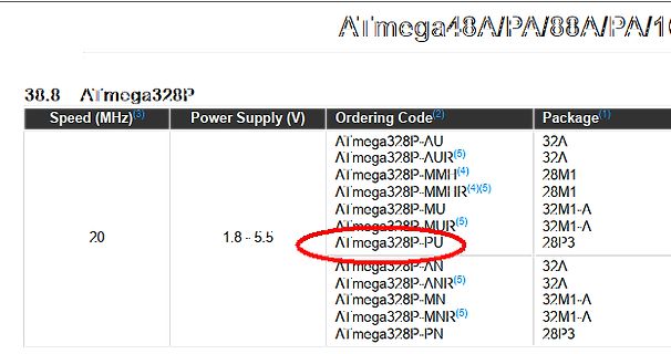
Tabellenausschnitt mit ATmega328P Bestellcodes
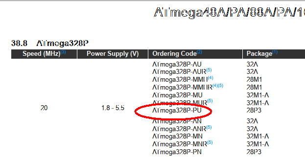
ATmega48A/PA/88A/PA/16... 38.8 ATmega328P Speed (MHz) Power Supply (V) Ordering Code Package ATmega328P-AU 32A ATmega328P-AUR 32A ATmega328P-MMI 2.8M1 ATmega328P-MMIR 2.8M1 ATmega328P-MU 32M1-A ATmega328P-MUIR 32M1-A ATmega328P-PU 28IP3 ATmega328P-AN 32A ATmega328P-ANIR 32A ATmega328P-MN 32M1-A ATmega328P-MNIR 32M1-A ATmega328P-PN 28IP3
in „ATmega: unerwatetes Reset“ · Mikrocontroller und Digitale Elektronik · · Screenshots
-
Datei
device2007.txt
ATTINY11, ATTINY12, ATTINY15L, ATTINY26, ATTINY26L, ATTINY28L, ATTINY28V, ATTINY2313, ATTINY2313V, ATMEGA8, ATMEGA8L, ATMEGA16, ATMEGA16L, ATMEGA32, ATMEGA32L, ATMEGA8515, ATMEGA8515L, ATMEGA8535, ATMEGA8535L, ATMEGA48*PDIP28, ATMEGA88*PDIP28, ATMEGA168*PDIP28, ATMEGA48V*PDIP28, ATMEGA88V*PDIP28, ATMEGA168V
in „24C04 beschreiben und auslesen“ · Mikrocontroller und Digitale Elektronik ·
-
Datei
wiring.c
// this needs to be called before setup() or some functions won't // work there sei(); // on the ATmega168, timer 0 is also used for fast hardware pwm // (using phase-correct PWM would mean that timer 0 overflowed half as often // resulting in different millis() behavior on the ATmega8 and ATmega168)
in „Sekunden,Minuten zählen mit der Funktion Millis()“ · Mikrocontroller und Digitale Elektronik ·
-
Datei
serial.h
UCSR0B= (1<<RXCIE) | (1<<TXCIE) | (1<<RXEN) | (1<<TXEN) #define UART0_CONFIGURE2 NOP //Ho, ho, hoo. 8 Bit,1 Stop, no parity #elif defined (__AVR_ATmega168__) || defined (__AVR_ATmega48__) || defined (__AVR_ATmega88__) || defined (__AVR_ATmega644__) #define TX0_BIT 1 #define TX0_PORT PORTD #define TX0
in „Atmel ist unter "Profis" nicht gerade beliebt - Warum?“ · Mikrocontroller und Digitale Elektronik ·
-
Datei
avr-size.txt
\Alpha Bord>avr-size --mcu=atmega169 -C ADC.o AVR Memory Usage ---------------- Device: atmega169 Program: 128 bytes (0.8% Full) (.text + .data + .bootloader) Data: 0 bytes (0.0% Full) (.data + .bss + .noinit) C:\Temp\AVR Programme
in „zu wenig speicher? atmega 169“ · Mikrocontroller und Digitale Elektronik ·
-
Datei
ausfuehrliche_Fehlermeldung.txt
\\arduino\\tools\\avr-gcc\\7.3.0-atmel3.6.1-arduino7/bin/avr-gcc" -w -Os -Wl,--gc-sections -mmcu=atmega88p -o "C:\\Users\\Michael Dallmann\\AppData\\Local\\Temp\\arduino-sketch-24D8B4E568FB3DD945C662CD9897EDFE/md-blink1.ino.elf" "C:\\Users\\Michael Dallmann\\AppData\\Local\\Temp\\arduino-sketch-24D8B4E568FB3DD945C662CD9897EDFE
in „Arduino Atmega88-PA Upload-Abbruch wegen Leerzeichen im Pfad“ · Mikrocontroller und Digitale Elektronik ·
-
Datei
ausfuehrliche-Fehlermeldung.txt
\\arduino\\tools\\avr-gcc\\7.3.0-atmel3.6.1-arduino7/bin/avr-gcc" -w -Os -Wl,--gc-sections -mmcu=atmega88p -o "C:\\Users\\Michael Dallmann\\AppData\\Local\\Temp\\arduino-sketch-24D8B4E568FB3DD945C662CD9897EDFE/md-blink1.ino.elf" "C:\\Users\\Michael Dallmann\\AppData\\Local\\Temp\\arduino-sketch-24D8B4E568FB3DD945C662CD9897EDFE
in „Arduino Atmega88-PA Upload-Abbruch wegen Leerzeichen im Pfad“ · Mikrocontroller und Digitale Elektronik ·
-
PDF
sd_mmc.pdf
der SD-Karte . . . . . . . . . . . . . . . . . . . . . . . 7 3.2 Benutzen der SPI-Schnittstelle am ATmega . . . . . . . . . . . . . . . . . 8 3.2.1 Initialisierung . . . . . . . . . . . . . . . . . . . . . . . . . . . . .8. 3.2.2 Bytes senden und empfangen . . . . . . . . . . . . . . . . . . . . . 9 3.3
in „MMC-Karte funktioniert nicht“ · Mikrocontroller und Digitale Elektronik ·
-
PDF
kicad_8450_dcm_liste_neu_v3.pdf
, 512B EEPROM ATMEGA8-16MU QFN/MLF32, 8k Flash, 1k SRAM, 512B EEPROM ATMEGA8-16PU PDIP28 Narrow, 8k Flash, 1k SRAM, 512B EEPROM ATMEGA8515-16AU TQFP44, 8k Flash, 512B SRAM, 512B EEPROM ATMEGA8515-16JU PLCC44, 8k Flash,
in „KiCAD Eeschema, Bibliotheksdokumentation *.dcm als PDF-Datei“ · Platinen ·
-
Datei
wiring_analog.c
if // there's something connected to AREF. analog_reference = mode; } int analogRead(uint8_t pin) { uint8_t low, high; #if defined(analogPinToChannel) #if defined(__AVR_ATmega32U4__) if (pin >= 18) pin -= 18; // allow for channel or pin numbers #endif pin = analogPinToChannel(pin); #elif defined
in „Arduino IDE mit Atmega32 - AD Wandler sind nicht benutzbar“ · Mikrocontroller und Digitale Elektronik ·
-
PDF
nRF24L01_.pdf
2.4GHz-HowTo von der Beschreibung abweichend sind die folgenden Verbindungen: • nRF24L01+ CE → Arduino D8 (ATMega8 PB0) • nRF24L01+ CSN → Arduino D4 (ATMega8 PD4) • nRF24L01+ IRQ → Arduino D3 (ATMega8 PD3) Gaaaanz wichtig der 100µF Kondensator nahe bei der 3,3V Versorgung für den nRF24L01+ nicht vergessen
in „Repeating und Routing Netzwerk mit Arduino und nRF24L01+“ · Projekte & Code ·
-
Datei
atmega32u2.patch
* 4, // 29 interrupt vectors + DEVFL_MKII_ONLY, + atmega32u2_io_registers, + false, + 0x07, 0x8000, // fuses + 0x66, // osccal + 1, // OCD revision + { + 0 // no mkI support + }, + { + CMND_SET_DEVICE_DESCRIPTOR, + { 0xF8,0x0F,0x60,0xF8,0xFF,0x3F,0xB9,0xF0
in „avarice und atmega32u2“ · Mikrocontroller und Digitale Elektronik ·