-
Datei
Vollfarbsteuerung_C.c
/* * Vollfarbsteuerung_C.c * * Created: 23.05.2014 17:56:48 * Author: Sam */ #define F_CPU 16000000UL #include <stdlib.h> #include <avr/io.h> // Informationen über den µC #include <avr/interrupt.h> // Definitionen der Interrupts #include <avr/pgmspace.h> #include
in „UART-Interrupt wird nicht ausgelöst“ · Mikrocontroller und Digitale Elektronik ·
-
PDF
AVR-ASM-Tutorial_16_05_08_v1.pdf
Widerstand abgeschaltet, bei einer 1 wird der Widerstand an den Eingangs-Pin zugeschaltet. • Bei den neuerenAVR (wie z.B.ATtiny13,ATtiny2313, ATtiny24/44/84,ATtiny25/45/85, ATmega48/88/168, usw.) kann man alsAusgang konfigurierte Pins toggeln (PORTx zwischen 0 und 1 „umschalten“), indem man eine 1 an die entsprechende
in „AVR-ASM-Tutorial: PDF 16.5.08“ · www.mikrocontroller.net ·
-
Datei
main.lst
main.elf: file format elf32-avr Sections: Idx Name Size VMA LMA File off Algn 0 .text 00000172 00000000 00000000 00000074 2**1 CONTENTS, ALLOC, LOAD, READONLY, CODE 1 .data 00000004 00800060 00000172 000001e6 2**0 CONTENTS, ALLOC,
in „AVR-GCC 4.7.2 Bug?“ · Mikrocontroller und Digitale Elektronik ·
-
Datei
OLED_2_42_SSD1309_test_igel1_v006b.ino
Information: ----------------------------------- OLED - Spec: 2.42 inch 2.42" OLED Display Module 128x64 LCD HD Screen Module SSD1309 7 Pin SPI/IIC I2C Serial Interface for Arduino UNO R3 OLED - Vendor: https://de.aliexpress.com/item/1005006473260235.html Recommended Readings: ---------------------
in „Induktiver Positionssensor - Fragen dazu“ · Mikrocontroller und Digitale Elektronik ·
-
Datei
AVR910JS_2313_v3_3_STK500.asm
;*************************************************************************** ;* ;* Title : AVR ISP (Auto adr inc, 19200bps) ;* Version : 3.2 ;* Last updated : 17/Jan/05 ;* Target : AT90S2313 @ 4Mhz (orig. AT90S1200) ;* File : AVR910_2313_v3_2.asm ;* Author(s) : Ole Saether, Terje Frostad, ;*
in „STK500 spinnt“ · Mikrocontroller und Digitale Elektronik ·
-
PDF
avrcpm_cpu_board.sch.pdf
3 A9_MISO D EX30 61 2 A8_MOSI GND GND GND PF0(ADC0) (RXD/PDI)PE0 Verbindung zu Controller ISP MEGA128-A Terminal-Board und V Erweiterungs-Board V X9 + http://www.mikrocontroller.net/articles/JTAG#Pinout_AVR-JTAG con terminal 3 MISO 1 2 VCC 1 2 + A9_MISO SCK 3 4 MOSI RX_PROP SCK RST GND A8_MOSI TX_PROP 3 4 /RESET_PRO /RESET_AVR 5 6 5 6 /RESET_AVR SDA_33 7 8 AVR ISP H1 H2 SCL_33 9 10 5 GND MOUNT-HOLE3.2 MOUNT-HOLE3.2 + X10 http://www.mikrocontroller.net/articles/AVR_In_System_Programmer#ISP 3 3 9 U1C V V 8 GND GND + + 10 1C
in „CP/M auf ATmega88“ · Mikrocontroller und Digitale Elektronik ·
-
PDF
ttester_ger109k.pdf
, 687mV B=428, 678mV B=380, 654mV BC556B PNP B=285, 689mV B=254, 668mV B=251, 684mV B=262, 653mV AC128 (Ge.) PNP B=63, 190mV B=59, 191mV B=59, 184mV B=48, 114mV BRY55/200 Thyristor Thyristor Thyristor Thyristor MAC97A6 Triac Triac Triac Triac Tabelle 5.3: Messergebnisse der Tests mit bipolaren Transistoren
in „Sammelbestellung Transistortester III - schnelle Runde“ · Markt ·
-
Datei
deinterleave2__2_.lst
main.out: file format elf32-avr Sections: Idx Name Size VMA LMA File off Algn 0 .text 0000010e 00000000 00000000 00000054 2**1 CONTENTS, ALLOC, LOAD, READONLY, CODE 1 .debug_aranges 00000020 00000000 00000000 00000162 2**0 CONTENTS
in „AVR/ATmega uint32_t Deinterleaving optimieren“ · Mikrocontroller und Digitale Elektronik ·
-
Datei
uart.c
UCSR1A #define UART1_CONTROL UCSR1B #define UART1_DATA UDR1 #define UART1_UDRIE UDRIE1 #elif defined(__AVR_ATmega64__) || defined(__AVR_ATmega128__) /* ATmega with two USART */ #define ATMEGA_USART0 #define ATMEGA_USART1 #define UART0_RECEIVE_INTERRUPT SIG_UART0_RECV #define UART1_RECEIVE_INTERRUPT SIG_UART1
in „SHT11 misst Mist“ · Mikrocontroller und Digitale Elektronik ·
-
PDF
Atiny2313.pdf
implement run-time changes of the internal clock frequency while still ensuring stable operation. 29 2543I–AVR–04/06 128 kHz Internal The 128 kHz Internal Oscillator is a low power Oscillator providing a clock of 128 kHz. The frequency is nominal at 3 V and 25°C. This clock may be selected as the system Oscillator
in „Suche tutorial“ · Mikrocontroller und Digitale Elektronik ·
-
PDF
attiny84.pdf
throughputs up to ten times faster than con- ventional CISC microcontrollers. 4 ATtiny24/44/84 8006H–AVR–10/09 ATtiny24/44/84 The ATtiny24/44/84 provides the following features: 2/4/8K byte of In-System Programmable Flash, 128/256/512 bytes EEPROM, 128/256/512 bytes SRAM, 12 general purpose I/O lines,
in „Attiny 84 ISP?!“ · Mikrocontroller und Digitale Elektronik ·
-
PDF
AVR_ATtiny_24_44_84.pdf
throughputs up to ten times faster than con- ventional CISC microcontrollers. 4 ATtiny24/44/84 8006K–AVR–10/10 ATtiny24/44/84 The ATtiny24/44/84 provides the following features: 2/4/8K byte of In-System Programmable Flash, 128/256/512 bytes EEPROM, 128/256/512 bytes SRAM, 12 general purpose I/O lines,
in „AVR Programm brennen ohne Bootloader“ · Mikrocontroller und Digitale Elektronik ·
-
PDF
Attiny24a-44a-84a.pdf
Frequency vs. OSCCAL Value V = 3V CC 16 85 °C 25 °C 14 -40 °C 12 )10 H ( y 8 n u r 6 F 4 2 0 0 16 32 48 64 80 96 112 128 144 160 176 192 208 224 240 OSCCAL (X1) 238 ATtiny24A/44A/84A 8183F–AVR–06/12 ATtiny24A/44A/84A 21.4 ATtiny84A 21.4.1 Current Consumption in Active Mode Figure 21-112. Active Supply
in „Kann jemand über meine Inialisierung drüberfliegen?“ · Mikrocontroller und Digitale Elektronik ·
-
Datei
main.c
16000000UL #include <stdint.h> // Header File für Datentypen (uint8_t, etc.) #include <stdlib.h> #include <avr/io.h> // Header File für IO Ports #include <avr/interrupt.h> // Header File Interrupt Vektoren #include <avr/pgmspace.h> // Markos für PGM Space // INCLUDES für UART #include "uart.h" #define ANZAHL1
in „µC rechnet falsch oder ich finde den Fehler nicht“ · Mikrocontroller und Digitale Elektronik ·
-
Datei
hello_world__3_.c
Steuerung der Solarzelle * 07.04.2016 * Version 1 *********************/ #include "u8g.h" #if defined(__AVR__) #include <avr/io.h> #endif uint8_t adc(uint8_t Nr); uint8_t stromadc(uint8_t Nr); u8g_t u8g; void u8g_setup(void); void sys_init(void); void u8g_setup(void) { //u8g_InitSPI(&u8g, &u8g_dev_ssd1306_128x64_hw_spi, U8G_PIN_NONE, U8G_PIN_NONE, PN(2, 1), PN(2, 0), U8G_PIN_NONE); // PB4 PB0 PC6 u8g_InitSPI(&u8g, &u8g_dev_pcd8544_84x48_hw_spi, PN(1,5), PN(1,4), PN(1,3), PN(1,0), PN(3,6)); //uint8_t u8g_InitSPI
in „zwei ADC zeigen dasselbe an“ · Mikrocontroller und Digitale Elektronik ·
-
PDF
ImplementierungEinerFiniteStateMachine.pdf
Problem soll mit der Tabellenversion gelöst werden. 6. Implementation des Toaster Beispiels auf einem AVR Die Implementation auf einem Atmel ATmega128 in C++ ist so ausgelegt, dass diese gut im AVR-Studio mit dem Simulator nachvollzogen werden kann. Als Sprache kommt C++ zum Einsatz, da erstens die Implementation
in „Artikel über Finite State Machines“ · Mikrocontroller und Digitale Elektronik ·
-
 Bild
Bild
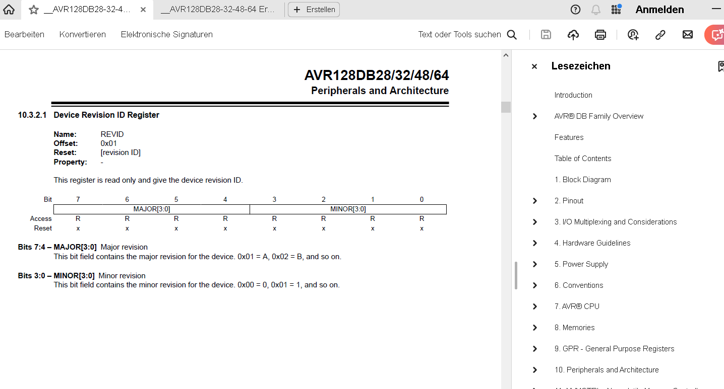
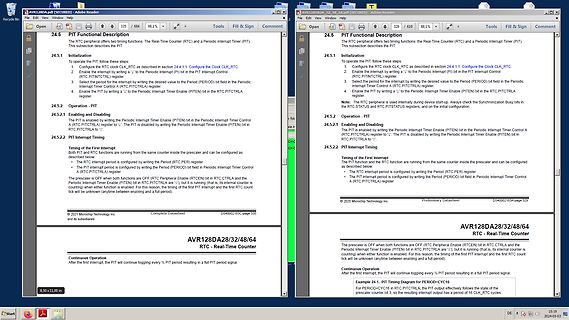
Ausschnitt eines Datenblatts für AVR128DA Mikrocontroller
AVR128DA28/32/48/64 RTC - Real-Time Counter 24.5 PIT Functional Description 24.5.1 Initialization 24.5.2 PIT Timing © 2021 Microchip Technology Inc.
in „AVR64EA28: PIT-Interrupt“ · Mikrocontroller und Digitale Elektronik · · Screenshots
-
PDF
tiny13.pdf
ensuring stable operation. Refer to “System Clock Prescaler” on page 25 for details. 24 ATtiny13 2535E–AVR–10/04 ATtiny13 128 kHz Internal The 128 kHz internal Oscillator is a low power Oscillator providing a clock of 128 kHz. The frequency is nominal at 3V and 25°C. This clock may be select as the system
in „ATtiny13 Datenblatt External Clock Source on T0-Pin“ · Mikrocontroller und Digitale Elektronik ·
-
Datei
gls330.bas
' Program: GSED1330.BAS written using Bascom-AVR ver 1.11.6.2 ' Basic program to interface with a graphic LCD ' which has a Seiko SED1330 controller. This program will set up ' the LCD and allow one to position and write text as well as load and display
in „LCD-Modul EPSON ECM-A0428 von Pollin“ · Mikrocontroller und Digitale Elektronik ·
-
 Bild
Bild
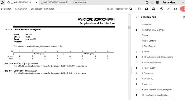
Datenblatt Ausschnitt AVR128DB Device Revision ID Register
AVR128DB28/32/48/64 Peripherals and Architecture 10.3.2.1 Device Revision ID Register Name: REVID Offset: 0x01 Reset: [revision ID] Property: This register is read only and give the device revision ID.
in „AVR128DA64 TCA1 funktioniert nicht mit alternativen Output?“ · Mikrocontroller und Digitale Elektronik · · Screenshots
-
Datei
led_matrix.asm
.nolist .include "C:\Programme\Atmel\AVR Tools\AvrAssembler\Appnotes\8515def.inc" .list .def tmp=r16 ;Universalregister deklarieren .def leds=r17 .def zahler=r19 .def shift_cnt=r20 .org 0 ;Stimmt die Interrupttabelle? Simulator springt bei
in „BCD Z ählen (AVR ASM)“ · Mikrocontroller und Digitale Elektronik ·
-
 Bild
Bild
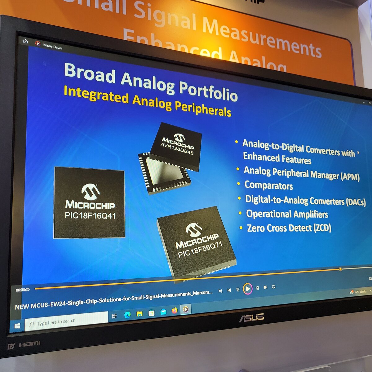
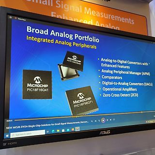
Präsentation von Microchip Analog-Peripheriegeräten auf Monitor
Signal Measurements Enhanced Analog Broad Analog Portfolio Integrated Analog Peripherals MICROCHIP AVR128DB48 Analog-to-Digital Converters with Enhanced Features Analog Peripheral Manager (APM) Comparators Digital-to-Analog Converters (DACs) Operational Amplifiers Zero Cross Detect (ZCD) MICROCHIP PIC18F16Q41
in „Embedded World 2024 - mehr Chips, Software uvam“ · Mikrocontroller und Digitale Elektronik · · Fotos
-
Datei
avr.txt
sein für Leute, die sich in die Programmierung der AVR Mikrocontroller einarbeiten wollen. Mit einfachen Assembler-Programmen wird ausprobiert, was sich mit den Input-Output-Registern eine AVR Mikrocontrollers so alles bewirken läßt. Um mit Assembler etwas
-
Datei
Wie_sag_ich_es_dem_AVR.txt
Zur Startseite Zur Artikelübersicht Wie sag ich's meinem AVR ? Einleitung Gerhard Paulus gp@gnomsoft.de Copyright (c) 2002 GNOM SOFT GmbH, Dresden Dieser Text ist für alle Leute interessant, die sich in die Programmierung der AVR Mikrocontroller einarbeiten wollen
in „Assembler Sprache erlernen“ · Mikrocontroller und Digitale Elektronik ·
-
Datei
main.c
#include <avr/io.h> #include <avr/interrupt.h> #include <util/delay.h> #include <QA/uart/uart.h> #include <Q/osc/osc.h> #include <Q/color_lcd/SSD1289.h> #include <Q/color_lcd/SSD1289_types.h> #ifndef F_USB #include <avr/iox128a1u.h> #endif #include "cfg/Qssd1289_cfg.h" #include <Q/Qcopy/memcopy.c> volatile bool draw_ready = false; void init_ebi(void) __attribute__ ((naked)) \ __attribute__ ((section (".init0"))); void
in „Grafikdisplay mit SSD1289 mit XMEGA, DMA und 16bit Interface sehr schnell“ · Mikrocontroller und Digitale Elektronik ·
-
Datei
main.c
#include <avr/io.h> #include <avr/interrupt.h> #include <util/delay.h> #include <QA/uart/uart.h> #include <Q/osc/osc.h> #include <Q/color_lcd/SSD1289.h> #include <Q/color_lcd/SSD1289_types.h> #ifndef F_USB #include <avr/iox128a1u.h> #endif #include "cfg/Qssd1289_cfg.h" #include <Q/Qcopy/memcopy.c> volatile bool draw_ready = false; void init_ebi(void) __attribute__ ((naked)) \ __attribute__ ((section (".init0"))); void
in „Grafikdisplay mit SSD1289 mit XMEGA, DMA und 16bit Interface sehr schnell“ · Mikrocontroller und Digitale Elektronik ·
-
Datei
main_und_ad7305.txt
################################################### main.c #include <avr/io.h> #include "stdlib.h" #include "intern_adc.h" // intern_ADC-Funktionen #include "ad7305.h" // DAC-Funktionen int main(void) { unsigned char sin_table[255] = { 0x7F,0x82,0x85,0x88,0x8B,0x8E, 0x91,0x94,0x97,0x9B
in „8bit DAC an Mega32“ · Mikrocontroller und Digitale Elektronik ·
-
Datei
Unterprogramme.h
UCSR1A #define UART1_CONTROL UCSR1B #define UART1_DATA UDR1 #define UART1_UDRIE UDRIE1 #elif defined(__AVR_ATmega64__) || defined(__AVR_ATmega128__) /* ATmega with two USART */ #define ATMEGA_USART0 #define ATMEGA_USART1 #define UART0_RECEIVE_INTERRUPT SIG_UART0_RECV #define UART1_RECEIVE_INTERRUPT SIG_UART1
in „Roboter-Linienverfolgung mit P-Regler und Ausweichmodus“ · Mikrocontroller und Digitale Elektronik ·
-
PDF
nRF24L01plus.pdf
Schnittstelle im Arduinosystem verdoppelt werden. z.B. C:\Program Files (x86)\Arduino\hardware\arduino\avr\cores\arduino\HardwareSerial.h #define SERIAL_RX_BUFFER_SIZE 64 ändern in #define SERIAL_RX_BUFFER_SIZE 128 Arduino muss danach neu gestartet werden. Linuxsystem als Server Letztlich benötigt man einen
in „Repeating und Routing Netzwerk mit Arduino und nRF24L01+“ · Projekte & Code ·
-
PDF
TempSensorKTY81-120.pdf
RPTC ADC Aref RPTCR 1 2) Insgesamt sollte durch den PTC nicht mehr als 1 mA fließen.U Aref,ist beim AVR 2,56 V. U R= => Rmin R1 PTC=2560Ohm I Bei -30 Grad Celsius besitzt der KTY81-100 einen minimalen Widerstand von 609 Ohm. R1=2560Ohm−609Ohm=1951Ohm R =2kOhm 1 3) Der Widerstand im Bezug zur Temperatur
in „Wieviel Strom kann ich aus Aref beziehen?“ · Mikrocontroller und Digitale Elektronik ·
-
PDF
AT90CAN128.pdf
Bytes 1K Byte 2K Bytes AT90CAN64 64K Bytes 2K Bytes 4K Bytes AT90CAN128 128K Bytes 4K Byte 4K Bytes 1.2 Part Description The AT90CAN32/64/128 is a low-power CMOS 8-bit microcontroller based on the AVR enhanced RISC architecture. By executing powerful instructions in a single
in „Umrechnen von analog to digital“ · Mikrocontroller und Digitale Elektronik ·
-
Datei
Funzt_nicht.txt
>>>: avrdude -u -c avr910 -P COM2 -p m8 Detected 1e950f = ATmega328P ampel_neu.hex: 7.808 / 65.536 Bytes (11,91%) >>>: avrdude -u -c avr910 -P COM2 -p m8 Detected 1e950f = ATmega328P ampel_neu.hex: 7.808 / 32.768 Bytes (23,83%
in „Probleme mit AVRDUDESS 2.13“ · Mikrocontroller und Digitale Elektronik ·
-
Datei
Tiny_Lighthouse.c
the trigger pulse F_CPU = 1600000 Hz as the Tiny runs in ATTIny15 compatibility mode */ #include <avr/io.h> #include <avr/eeprom.h> #include <avr/interrupt.h> #include <avr/pgmspace.h> #include <util/delay.h> typedef struct LighthouseFlags { uint8_t Direction: 2; //! see table below for values uint8
in „LED Fader mit NE555 fadet nicht“ · Analoge Elektronik und Schaltungstechnik ·
-
Datei
freq-gen.c
/* mega48/88/168, Quarz 20MHz link auf libm.a LCD Ausgabe: lcd_pos(char zeile,char spalte) lcd_out(char "zeichenkette") lcd_data(char zeichen) Taster C0,C1,C2 - Runter, Hoch, Low/High LCD Backlight an B3 thx an Arne Groh für die Grundidee thx an Herrn Dannegger für 'outfloat' */ #include <avr/io.h> #include <avr/interrupt.h> #include <avr/eeprom.h> #include <util/delay.h> #include <stdio.h> #include <stdlib.h> #include "lcd.h" uint8_t lcd_string[1], save, eeChar EEMEM; uint16_t takt, timer0count
in „Einstellbarer Frequenzgenerator für 0.12 Hz - 8 MHz mit Atmega 8 und Bascom“ · Projekte & Code ·
-
PDF
AVR-Tutorial.pdf
Widerstand abgeschaltet, bei einer 1 wird der Widerstand an den Eingangs-Pin zugeschaltet. • Bei den neuerenAVR (wie z. B. ATtiny13, ATtiny2313, ATtiny24/44/84, ATtiny25/45/85, ATmega48/88/168, usw.) kann man alsAusgang konfigurierte Pins toggeln (PORTx zwischen 0 und 1 „umschalten“), indem man eine 1 an die
in „AVR-Tutorial als PDF“ · Offtopic ·
-
Datei
MD_NMRA_DCC.h
dcc detect and 1 for dcc generating) */ #ifndef NMRA_DCC_DRIVER #define NMRA_DCC_DRIVER #include <avr/eeprom.h> #define NULL 0 #define TRUE 1 #define FALSE 0 #ifndef F_CPU #error "NO FCPU SPEED DEFINED!!" #endif //NOTE: Check ISR in .c, there you must implement all used timers of output_t & accesoirs_t
in „FULL NMRA DCC Library, Encoder, Generator, Bremsmodul“ · Projekte & Code ·
-
PDF
assembler_beginner.pdf
lang- samer zu verarbeiten sind als Daten in Re- gistern. Dafür besitzt schon der zweit- kleinste AVR immerhin 128 Bytes an SRAM-Speicher. Da passt schon einiges mehr rein als in 32 popelige Register. Die größeren AVR ab AT90S8515 aufwärts bieten neben den eingebauten 512 Bytes zusätzlich die Mög- lichkeit
in „Assembler Tutorial als PDF ?“ · Mikrocontroller und Digitale Elektronik ·
-
Datei
CFD.asm
.include "AVR128DB48def.inc" .def tmpi = r15 .def tmp0 = r16 .macro CCP ldi tmp0,CPU_CCP_IOREG_gc sts CPU_CCP,tmp0 .endmacro rjmp reset .org CLKCTRL_CFD_vect sbi VPORTB_IN,3 lds tmpi,CLKCTRL_MCLKINTFLAGS sts CLKCTRL_MCLKINTFLAGS
in „AVR128DB - Clock Failure Detection“ · Mikrocontroller und Digitale Elektronik ·
-
Datei
Sender_V3.c
#define F_CPU 12000000L #define BAUD 19200L #include <avr/io.h> #include <util/delay.h> #include <stdint.h> #include <stdlib.h> #include <avr/interrupt.h> /*überprüfen ob baudrate mit CPU Frequenz zusammenpasst*/ #define UBRR_VAL ((F_CPU+BAUD * 8)/(BAUD*16
in „ATmega 8 ADC daten an RS232“ · Mikrocontroller und Digitale Elektronik ·
-
Datei
main.c
#include <avr/io.h> #include <util/delay.h> #include <avr/interrupt.h> #include <stdio.h> #include <stdbool.h> #include "TWI_Master.h" #include "mydefs.h" #include "taster.h" #include "functions.h" #include "ks108
in „Funktionszeiger in C“ · Mikrocontroller und Digitale Elektronik ·
-
Datei
BlinkingLED.txt
r24 6a: 20 83 st Z, r18 6c: 80 e0 ldi r24, 0x00 ; 0 6e: 90 e0 ldi r25, 0x00 ; 0 70: a8 e4 ldi r26, 0x48 ; 72 72: b3 e4 ldi r27, 0x43 ; 67 74: 89 83 std Y+1, r24 ; 0x01 76: 9a 83 std Y+2, r25 ; 0x02 78: ab 83 std Y+3, r26 ; 0x03 7a: bc 83 std Y+4, r27 ; 0x04 #endif __builtin_avr_delay_cycles(__ticks_dc)
in „AvrStudio 5 Programm zu groß für Attiny 13“ · Mikrocontroller und Digitale Elektronik ·
-
PDF
ttester.pdf
8-bit AVR with 4/8/16/32KBytes In-System Programmable Flash - ATme- ga48 - ATmega328,. Manual, 8271D-AVR-05/11, 2011 [4] Atmel Corporation Atmel AVR126: ADC of megaAVR in Single Ended Mode,. Application Note,
in „Sammelbestellung Transistortester III - schnelle Runde“ · Markt ·
-
Datei
eemanager.ino
----------------------------------------------------------- */ /* Atmel 512kb / 64 kb EEPROM ATMLUO48 AT24C512B */ /* ---------------------------------------------------------------------------------------- */ #define WORD_MASK 0xFFFF #define EEDEVICEADRDRESS 0x500000 #define EEPAGESIZE 0x80 /* Löscht
in „Cache Strategien für E2PROM in uC“ · Mikrocontroller und Digitale Elektronik ·
-
PDF
ATtiny261A_Complete.pdf
throughputs up to ten times faster than con- ventional CISC microcontrollers. 4 ATtiny261A/461A/861A 8197C–AVR–05/11 ATtiny261A/461A/861A The ATtiny261A/461A/861A provides the following features: 2/4/8K byte of In-System Program- mable Flash, 128/256/512 bytes EEPROM, 128/256/512 bytes SRAM, 16 general purpose
in „USI Interface als SPI Schnittstelle beim ATtiny261A“ · Mikrocontroller und Digitale Elektronik ·
-
Datei
bm01.asm
bm01.elf: file format elf32-avr Disassembly of section .text: 00000000 <__vectors>: 0: 0c 94 3e 00 jmp 0x7c ; 0x7c <__ctors_end> 4: 0c 94 50 00 jmp 0xa0 ; 0xa0 <__bad_interrupt> 8: 0c 94 50 00 jmp 0xa0 ; 0xa0 <__bad_interrupt> c:
in „FixedPoint in C und C++“ · Mikrocontroller und Digitale Elektronik ·
-
PDF
RN-Mega_Board.pdf
für Anwender, Bastler und Entwickler konzipiert die bereits Erfahrungen mit AVR-Controllern haben oder denen die kleineren AVR´s wie Mega8/Mega32 oder Mega128 noch nicht ganz ausreichen bzw. zu wenig Reserven bieten. Dieses Modul nutzt den neusten Controllerchip ATMega2560. Er dürfte derzeit ohne Frage einer der leistungsfähigsten AVR Controller überhaupt sein. Er bietet zum Beispiel wesentlich mehr Funktionen, Speicher als der recht bekannte Mega128. Dennoch ist dieses Modul genauso einfach zu programmieren wie auch die kleineren
in „ATmega2560 spinnt“ · Mikrocontroller und Digitale Elektronik ·
-
Datei
DC_Motor_Regler.c
aber schon reichen. Die Schaltungsbeschreibung, mit der man ggf. auch ohne Schaltplan auskommt: Ein AVR-Controller bekommt seine Versorgungsspannung von einem 5V-Regler (78L05) und wird mit passenden Abblockkondensatoren an Vcc (ggf. Vadc+Vref) mit internem 8 MHz Taktgeber betrieben. Der Sollwert fuer
in „Drehzahlregler für DC-Motor, ATmega48-328“ · Projekte & Code ·
-
Datei
irmp_trunk.patch
56_KHZ (IRSND_FREQ_TYPE) (56000) -# define IRSND_FREQ_455_KHZ (IRSND_FREQ_TYPE) (455000) -#else // AVR -# if F_CPU >= 16000000L -# define AVR_PRESCALER 8 -# else -# define AVR_PRESCALER 1 -# endif -# define IRSND_FREQ_TYPE uint8_t -# define IRSND_FREQ_30_KHZ (IRSND_FREQ_TYPE) ((F_CPU / 30000 / AVR_PRESCALER
in „IRMP - Infrared Multi Protocol Decoder“ · Projekte & Code ·
-
PDF
wama-online-dokumentation-public.pdf
V_Ref 2.56V // Definitionen und Einstellungen #define UART_BAUD_RATE 9600 #define UART_TX_BUFFER_SIZE 128 #define F_CPU 16000000 #define F_SAMPLE (50*16*7) // Signalfrequenz * Samples pro Welle * Anzahl der ADC // Includes #include <stdlib.h> // Zeug wie z.B. ltoa() #include <avr/io.h> // Definitionen für das spezifische Device #include <avr/interrupt.h> // Interrupt Krams #include <avr/pgmspace.h> // Zugriffe auf den Programmspeicher #include <stdint.h> // Definitionen der Integertypen fixer Länge #include <avr/wdt.h> // Watchdog //#include
-
PDF
MCP794xx.pdf
minute 0000000 = Disable digital trimming When CRSTRIM = 1: 1111111 = Add or subtract 254 clock cycles 128 times per second 1111110 = Add or subtract 252 clock cycles 128 times per second • • • 0000010 = Add or subtract 4 clock cycles 128 times per second 0000001 = Add or subtract 2 clock cycles 128 times
in „MCP794xx EUI-64 Node Adresse“ · Mikrocontroller und Digitale Elektronik ·