Suchergebnisse für "ESP32-S2"
28 VCC VIN 2 5 D 6 - PWM730 9 IO33 IO5 29 SDA SDA C F C4 mlcc 100V 4.7u 2 1 UVADIM 10 IO25 IO18 30 SCL SCL IC13 M U 2 1 D 0 11 IO26 IO19 31 SQW SQW 4N35S -TA1 S 0 IC5 R14 2 1 TASTER 12 IO27 NC 32 32 K 32 K R21 T 19
in
„Probleme mit Konstantstromtreiber / gatetreiber“
·
Analoge Elektronik und Schaltungstechnik
·
05.05.2020 04:15
Content-Length: 0"); AddSipLine(""); SendUdp(); iSignal = 0; } void Sip::Ack(const char *p) { char ca[32 ]; bool b = ParseParameter(ca, (int)sizeof(ca), "To: <", p, '>'); if (!b) return; pbuf[0] = 0; AddSipLine("ACK %s SIP/2 .0", ca); AddCopySipLine(p, "Call-ID: "); int cseq = GrepInteger(p, "\nCSeq: ");
in
„Sipdial per ESP8266 an Fritzbox“
·
Projekte & Code
·
19.04.2019 12:57
32 10uF GND 14 IO12 IO4 33 15 GND1 IO0 34 16 IO13 IO2 35 17 SD2 IO15 36 T_DATA GND TP2 TP1 SD3 SD1 18 CMD SD0 37 +5V 19 EXT_5V CLK 38 ESP 32 -DEVKITC-32 D Header: 691313510004 Plug: 691351500004 CAN_P 1 1 CAN_N 2 2 GND 3 3 IC3 VIN 4 4 GND TJA1050T-CM/118 J1 1 8 N CAN_P 691313510004 2 TXD S 7 G JP2 3 GND CANH 6 CAN_N VIN 1 4 VCC CANL 5 2 +5V RXD VREF VDD-LDO 3 R1 JP3 +C5 C6 3 CAN_P CAN_TERM 1 V F CAN_N 2 10uF
in
„Junkers CAN-Bus Protokoll“
·
Haus & Smart Home
·
13.10.2021 16:38
with HAL Library # include "gpio.h" # if defined(_IRSND_H_) # include"tim.h" # endif # define ARM_STM32 _HAL # define F_CPU SystemCoreClock #elif defined(__SDCC_stm8) // STM8 # define SDCC_STM8 #elif defined(TARGET_IS_BLIZZARD_RA2 ) // TI Stellaris (tested on Stellaris Launchpad with Code Composer Studio
in
„IRMP - Infrared Multi Protocol Decoder“
·
Projekte & Code
·
31.10.2018 00:31
with HAL Library # include "gpio.h" # if defined(_IRSND_H_) # include"tim.h" # endif # define ARM_STM32 _HAL # define F_CPU SystemCoreClock #elif defined(__SDCC_stm8) // STM8 # define SDCC_STM8 #elif defined(TARGET_IS_BLIZZARD_RA2 ) // TI Stellaris (tested on Stellaris Launchpad with Code Composer Studio
in
„IRMP - Infrared Multi Protocol Decoder“
·
Projekte & Code
·
31.10.2018 16:39
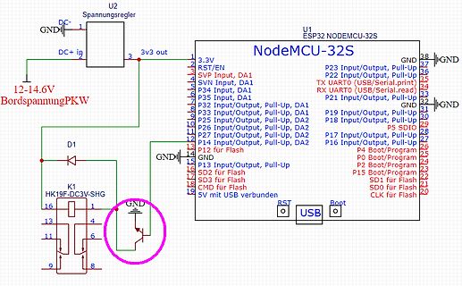
Bild
U2 Spannungsregler
GND
DC+ in
12-14.6V
BordspannungPKW
D1
K1 HK19F-DC3V-SHG
3v3 out
3,3V
RST/EN
SVP Input, DA1
SVN Input, DA1
P34 Input, DA1
P35 Input, DA1
P32 Input/Output, Pull-Up, DA1
P33 Input/Output
in
„ESP32 im PKW an Spannungsteiler Relais schalten“
·
Analoge Elektronik und Schaltungstechnik
·
17.06.2025 21:53
·
Schaltpläne
beziehe mich im folgenden auf die k8055d.dll vom April 2004 mit 21 Funktionen. Also: Wie macht man eine 32 -Bit Importlibrary, wenn man keine Objektdateien und keine Quelldateien hat? Diese Frage hat schon Microsoft bewegt... http://support.microsoft.com/default.aspx?scid=kb;en-us;131313 (Ob die dreifache
in
„Velleman K8055 und Cygwin GCC...“
·
Softwareentwicklung
·
11.10.2006 23:47
idx] = src[idx] @micropython.viper def memcpyHW(src: ptr16, dest: ptr16, size:int): idx: int = size//2 while (idx:=idx-1) >= 0: dest[idx] = src[idx] @micropython.viper def memcpyW(src: ptr32 , dest: ptr32 , size:int): idx: int = size//4 while (idx:=idx-1) >= 0: dest[idx] = src[idx] def test(): cpufreq(240
in
„Micropython Wetterstation“
·
Projekte & Code
·
25.01.2026 05:12
and union objects (except intrinsic vectors __m64, __m128, __m256, __m512) segment word size 16 bit 32 bit 64 bit compiler M o W M o W M G M W M L i r l t r l t c u c n c u s n o s n o O e O o , f d m f d m S c S s S t t p D t , max number of integer registe0s 2 2 2 1 1 2 2 1 2 used for return max number
in
„C und C++ kompatibilität“
·
Mikrocontroller und Digitale Elektronik
·
24.01.2024 10:27
(__SDCC_stm8) // STM8 # define SDCC_STM8 #elif defined(TARGET_IS_BLIZZARD_RA2 ) // TI Stellaris (tested on Stellaris Launchpad with Code Composer Studio) # define STELLARIS_ARM_CORTEX_M4 # define F_CPU (SysCtlClockGet()) #elif defined(__xtensa__) // ESP 8266 (Arduino) # include
in
„IR Fernbedienung mit IRSND“
·
Mikrocontroller und Digitale Elektronik
·
03.08.2020 18:34
1 2 3 4 5 6 7 8 Switch To GPIO curcuit Measure Curcuit Power Supply Switch Ignition Voltage Q2 U4 J1 +12V Q8 IRF4905 P7803-2000-S +3.3V +3V3 Power IRF4905 2 3 2 V_EIN 1 3 2 IN DUT V_EIN 3 2 U_IGN D C1 1
in
„Again: ESP32 external Power funktioniert nicht“
·
Mikrocontroller und Digitale Elektronik
·
03.12.2022 12:04
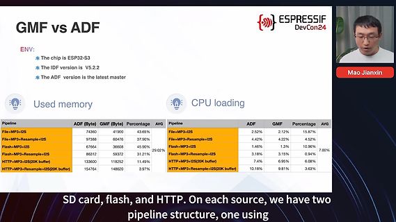
Bild
GMF vs ADF
ENV:
* The chip is ESP 32 -S 3
* The IDF version is V5.2 .2
* The ADF version is the latest master
ESPRESSIF DevCon24
Mao Jianxin
Used memory
Pipeline ADF GMF Percentage
File+MP3+I2 S 74360 41900 43.65%
File+MP3+Resample+I2 S 97388
in
„Komponenten und Buildsystem – Espressif DevCon 2024, Tag 2“
·
Mikrocontroller und Digitale Elektronik
·
04.09.2024 23:45
·
Screenshots
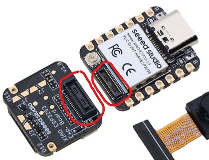
Bild
seeed studio
Model: XIAO ESP 32 -S 3
FCC ID: ZIT-XIAOESP32 S 3
FC CE
R
B
J2
J3
D11
D12
v1.0
in
„Wer kennt diese Steckverbindung?“
·
Mikrocontroller und Digitale Elektronik
·
10.08.2023 23:28
·
Platinenfotos
▯1 ▯2 ▯3 ▯4 ▯5 ▯6 Voltage Regulator ESP 8266 ▯A DC1 +12V U2 +3.3V H3 ▯A 1 3 2 GND 3 SW1 4 GND 1 1 PWM2 H2 2 VIN VOUT 4 U1 2 .4GHz 2 2 1 3 EP 1 1 2 1 22 GND 2 1 ADJ/GND 2 RST TXD 21 3 2 13 ADC RXD 20 4 3 GND
in
„PWM Lüfter Steuerung mit ESP8266 Tacho Problem“
·
Mikrocontroller und Digitale Elektronik
·
21.04.2025 19:58
/* * Connect the SD card to the following pins: * * SD Card | ESP 32 * D2 - * D3 SS = D5 * CMD MOSI = D23 * VSS GND * VDD 3.3V * CLK SCK = D18 * VSS GND * D0 MISO = D19 * D1 - */ #include "FS.h" #include "SD.h" #include "SPI.h" // const char * UDPWort = "14:14:44 <
in
„GPS Logger mit Atmega328 oder ESP8266“
·
Mikrocontroller und Digitale Elektronik
·
11.11.2020 00:23
long SleepTimer = (SleepDuration * 10 - ((CurrentMin % SleepDuration) * 60 + CurrentSec)); //Some ESP 32 are too fast to maintain accurate time esp _sleep_enable_timer_wakeup((SleepTimer+20) * 1000000LL); // Added extra 20-secs of sleep to allow for slow ESP 32 RTC timers #ifdef BUILTIN_LED pinMode(BUILTIN_LED
in
„ESP8266 mit Waveshare 7,5" E-Paper - funktioniert nicht“
·
Mikrocontroller und Digitale Elektronik
·
10.07.2022 23:29
E-EN 7 EN SDCMD 20 E-CMD R 1 6 X2 6 SDCLK 21 E-CLK 4 0 2 25q80bvsig /XTAL2 XTAL1 / 8 XPD-DCDCSDIO0 22 E-D0 R 1 2 E-RX 0 0 E-RST 32 RST# SDIO1 23 E-D1 3 2 5 26MHZ 2 5 1 3 E-TX F F 33 GND RES12K 31 1 R8 2 4 2 2 2 2 4 C 1 C 1 ESP 8266 12K
in
„SonOff S20 Leben, wirken und widerbelebung. :-)“
·
Haus & Smart Home
·
12.11.2022 21:52
compiler # if defined(__12F1840) // XC8 compiler # define Pre_Scaler 1 // define prescaler for timer2 e.g. 1,4,16 # define F_CPU 32000000UL // PIC frequency: set your freq here # define PIC_Scaler 2 // PIC needs /2 extra in IRSND_FREQ_32 _KHZ calculation for right value # else // C18 compiler # define
in
„IR Fernbedienung mit IRSND“
·
Mikrocontroller und Digitale Elektronik
·
03.08.2020 18:32
ZCZ 3 6 2 0 2 0 E-RST RST# SDIO1 E-D1 E-D3 WP# CLK E-CLK / 26MHZ / 33 31 1 R4 2 1 4 5 0 P 1 P GND RES12K GND DI E-D1 2 1 2 1 12K|F|0603 5V C C ESP 8266 VCC_BAR 25q80bvsig 1 1 hk32 f-g-005-hs 4 1 C 4 OUT B 2 N -
in
„Sonoff - seltsamer Kondensator“
·
Haus & Smart Home
·
12.04.2017 09:40
compiler # if defined(__12F1840) // XC8 compiler # define Pre_Scaler 1 // define prescaler for timer2 e.g. 1,4,16 # define F_CPU 32000000UL // PIC frequency: set your freq here # define PIC_Scaler 2 // PIC needs /2 extra in IRSND_FREQ_32 _KHZ calculation for right value # else // C18 compiler # define
in
„IRSND Daten für Roomba“
·
Mikrocontroller und Digitale Elektronik
·
21.02.2019 22:06
(",",argBegin+2 ); this->PW = this->decodeOnValue(s .substring(argBegin, argEnd)); } argBegin = s .indexOf("url:"); if(argBegin>0){ argEnd = s .indexOf(",",argBegin+2 ); this->TARGETURL = this->decodeOnValue(s .substring(
in
„DTZ541 mMe Datenlogger mit ESP (WEB-Sicht)“
·
Mikrocontroller und Digitale Elektronik
·
26.06.2021 16:55
1 2 3 4 5 6 7 8 A A U1 ESP 32 -WROOM-32 D(16MB) B GND 39 GND B GND 1 38 2 GND GND 37 GND VCC VDD33 IO23 WS2812 Ch3 EnableEN IO22 36 SCL 12V Input SENSOR_VP TXD0 35 TX 12V Input Rot 34 6 SENSOR_VN RXD0 33 RX 12V Inpu7 IO34 IO21 32 SDA 5v InputIO35 NC nicht verbunden 5v Input GIO32 IO19 31WS2812 Ch4 12 V Output ChIO33au IO18 30 12 V Output Ch3 Gruen 12 V Output Ch1 Rot 29WS2812 Ch2 s PWM signal at boot 11 IO25 IO5 28 12 V Output
in
„LD1117 3.3 V wird warm“
·
Analoge Elektronik und Schaltungstechnik
·
01.01.2021 21:02
OUT2 ESP 32 -S 3-WROOM-1(N8R2 ) B C6 U7 C12 DSUB1 1u ST3232BDR_C2987706 0.1u SUB-DRAF-607A-002 5 4 1 16 1 C7 2 C1+ VCC 15 6 11 1u 3 V+ GND 14 2 4 C1- DOUT1 13 7 GND 5 C2 + RIN1 12 3 +3V3 6 C2 - ROUT1 11 8 +3V3
in
„Datenlogger ESP32“
·
Mikrocontroller und Digitale Elektronik
·
17.01.2024 14:26
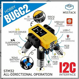
Bild
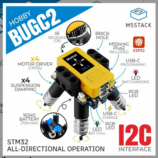
HOBBY BUGC2 M5STACK IR RECEIVER G36 BRICK HOLE M5StickC Plus2 INCLUDED ESP 32 USB-C PROGRAMING x4 MOTOR DRIVER (L9110S ) x4 SUSPENSION DAMPING USB-C CHARGE RGB LED LED BAT CHARGING 16340 BATTERY (700mAh) RGB LED USB-C CHARGE LED BAT FULL I2 C INTERFACE STM32 ALL-DIRECTIONAL OPERATION
in
„Bauteil-News: Entwicklerboards, Elektromechanik und vieles andere mehr“
·
Mikrocontroller und Digitale Elektronik
·
11.06.2024 23:45
·
Screenshots
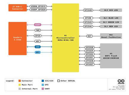
Bild
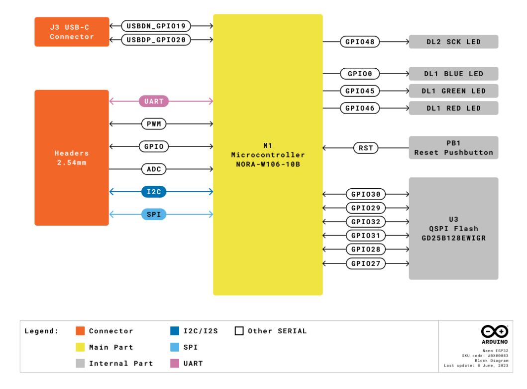
J3 USB-C Connector, USBDN_GPIO19, USBDP_GPIO20, M1 Microcontroller NORA-W106-10B, GPIO48, DL2 SCK LED, GPIO00, DL1 BLUE LED, GPIO45, DL1 GREEN LED, GPIO46, DL1 RED LED, UART, PWM, GPIO, ADC, I2 C, SPI, PB1 Reset Pushbutton, RST, U3 QSPI Flash GD25B128EWIGR, GPIO30, GPIO29, GPIO32 , GPIO31, GPIO28, GPIO27, Legend: Connector, I2 C/I2 S , SPI, UART, Main Part, Other SERIAL, Internal Part, ARDUINO Nano ESP 32 , SKU code: AR800083, BSKU Display, Last update: 8 June, 2023
in
„Arduino Nano mit ESP32-Prozessor“
·
Mikrocontroller und Digitale Elektronik
·
17.07.2023 22:09
·
Diagramme
color: white; padding: 16px 40px;"); client.println("text-decoration: none; font-size: 30px; margin: 2 px; cursor: pointer;}"); client.println(".button2 {background-color: #555555;}</style></head>"); // Web Page Heading client.println("<body><h1>Hardy ESP 32 Web Server</h1>"); // Display current state,
in
„sketch stört webserver - wer kann helfen?“
·
Mikrocontroller und Digitale Elektronik
·
24.02.2019 16:57
(",",argBegin+2 ); this->PW = this->decodeOnValue(s .substring(argBegin, argEnd)); } argBegin = s .indexOf("url:"); if(argBegin>0){ argEnd = s .indexOf(",",argBegin+2 ); this->TARGETURL = this->decodeOnValue(s .substring(
in
„Digitale Stromzähler auslesen und in DB speichern“
·
Mikrocontroller und Digitale Elektronik
·
19.02.2022 21:49
(",",argBegin+2 ); this->PW = this->decodeOnValue(s .substring(argBegin, argEnd)); } argBegin = s .indexOf("url:"); if(argBegin>0){ argEnd = s .indexOf(",",argBegin+2 ); this->TARGETURL = this->decodeOnValue(s .substring(
in
„Digitale Stromzähler auslesen und in DB speichern“
·
Mikrocontroller und Digitale Elektronik
·
11.09.2022 19:20
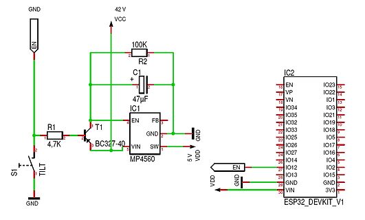
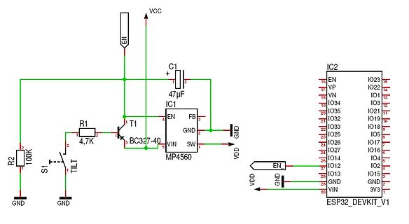
Bild
GND 42 V VCC 100K R2 C1 + 47µF IC1 EN FB GND 5 V VDD T1 BC327-40 R1 4.7K S 1 TILT GND IC2 EN VP VN IO34 IO35 IO32 IO33 IO26 IO27 IO14 IO12 IO13 VIN VDD GND GND 3V3 IO23 IO22 IO21 IO19 IO18 IO17 IO16 IO5 IO4 IO2 IO15 VIN ESP 32
in
„Bewegungssensor für Fahrrad Alarm“
·
Mikrocontroller und Digitale Elektronik
·
20.08.2023 14:32
·
Schaltpläne
Bild
VCC EN C1 47µF FB GND SW VIN T1 BC327-40 R1 4,7K R2 100K S 1 TILT GND IC1 MP4560 IC2 ESP 32 _DEVKIT_V1 EN VP VN IO35 IO32 IO25 IO26 IO27 IO14 IO12 IO13 GND VIN IO23 IO22 IO21 IO19 IO18 IO3 IO5 IO17 IO16 IO4 IO2 IO15 GND 3V3 VDD GND
in
„Bewegungssensor für Fahrrad Alarm“
·
Mikrocontroller und Digitale Elektronik
·
20.08.2023 00:57
·
Schaltpläne
(",",argBegin+2 ); this->PW = this->decodeOnValue(s .substring(argBegin, argEnd)); } argBegin = s .indexOf("url:"); if(argBegin>0){ argEnd = s .indexOf(",",argBegin+2 ); this->TARGETURL = this->decodeOnValue(s .substring(
in
„DTZ541 mMe Datenlogger mit ESP (WEB-Sicht)“
·
Mikrocontroller und Digitale Elektronik
·
28.08.2021 22:26
compiler # if defined(__12F1840) // XC8 compiler # define Pre_Scaler 1 // define prescaler for timer2 e.g. 1,4,16 # define F_CPU 32000000UL // PIC frequency: set your freq here # define PIC_Scaler 2 // PIC needs /2 extra in IRSND_FREQ_32 _KHZ calculation for right value # else // C18 compiler # define
in
„IRMP - Infrared Multi Protocol Decoder“
·
Projekte & Code
·
28.12.2020 11:12
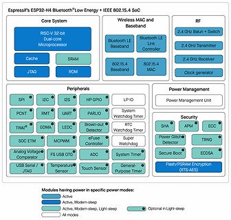
Bild
Espressif ESP 32 -H4 Bluetooth® Low Energy + IEEE 802.15.4 SoC
Core System
RISC-V 32 -bit Dual-core Microprocessor
Cache
SRAM
JTAG
ROM
Wireless MAC and Baseband
Bluetooth LE Baseband
Bluetooth LE Link Controller
802.15.4 Baseband
802.15.4 MAC
RF
2 .4 GHz Balun + Switch
2 .4 GHz Transmitter
2 .4 GHz Receiver
Clock generator
Peripherals
SPI
I2 C
I2 S
HP GPIO
LP IO
PCNT
RMT
UART
PARLIO
TWAI®
GDMA
LEDC
Brown-out Detector
System Watchdog Timer
SOC ETM
MCPWM
in
„ESP32-H4 mit zweikernigem RISC/V-Prozessor; OrangePi 5 Pro mit WiFi / Bluetooth“
·
Mikrocontroller und Digitale Elektronik
·
12.04.2024 16:37
·
Diagramme
Bild
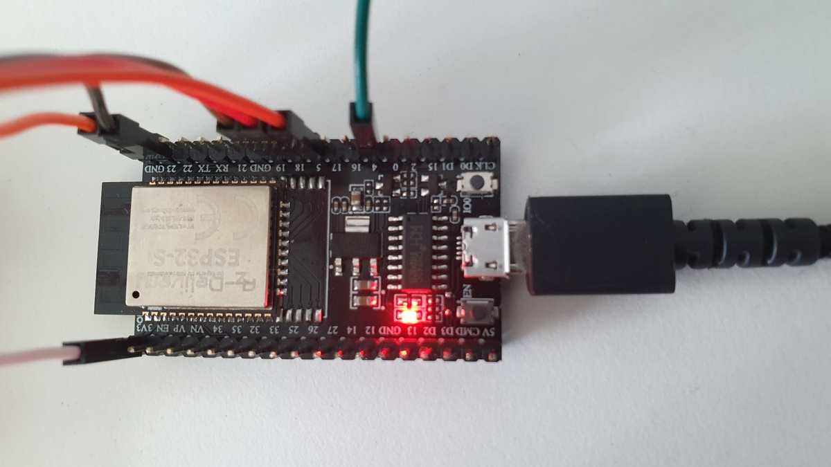
ESP 32 -S
GND 23 RX 22 TX 21 GND 19 18 17 15 14 13 12 2 0 CLK D0 D15
5V CMD D3 D2 GND 13 14 25 26 32 33 34 VIN EN VP VN V3
in
„ESP-32 SPI sendet falsche bits“
·
Mikrocontroller und Digitale Elektronik
·
08.08.2023 14:37
·
Platinenfotos
(",",argBegin+2 ); this->PW = this->decodeOnValue(s .substring(argBegin, argEnd)); } argBegin = s .indexOf("url:"); if(argBegin>0){ argEnd = s .indexOf(",",argBegin+2 ); this->TARGETURL = this->decodeOnValue(s .substring(
in
„Digitale Stromzähler auslesen und in DB speichern“
·
Mikrocontroller und Digitale Elektronik
·
14.05.2022 17:47
addPixelColor(m, 1, dimmer); if(hmark > 0) { for(byte i = 0; i<12; i++) { addPixelColor((5*i), 2 , hmark); } } h %= 12; h *= 5; h += (m/12); addPixelColor(h, 0, dimmer); // 0x RR GG BB if(fader) { byte dim_s 1 = dimmer; byte dim_s 2 = 0; byte px_s 2 = s +1; if(px_s 2 >= 60) px_s 2 = 0; unsigned long curMillis = millis()-lastMillis; if(curMillis < 250) { dim_s 2 = 0; dim_s 1 = dimmer; }else{ dim_s 2 = map(curMillis, 250, 1000, 0, dimmer); dim_s 1 = dimmer - map(curMillis, 250, 1000, 0, dimmer); } addPixelColor(s , 0, dim_s 1); addPixelColor(px_s 2 , 0, dim_s 2 ); }else
in
„LED Uhr mit RTC braucht Taster“
·
Mikrocontroller und Digitale Elektronik
·
08.07.2021 14:24
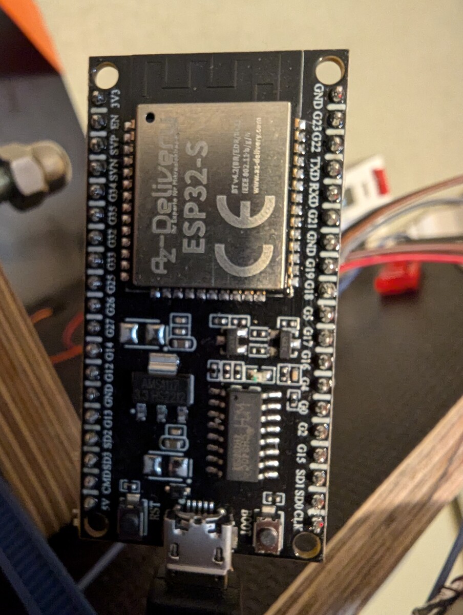
Bild
Az-Delivery ESP 32 -S 3V3 EN SVP G34 G35 G32 G33 G25 G26 G27 G14 G12 G13 GND SD2 SD3 G15 G2 G16 G17 G18 G19 GND RXD TXD G22 G23 GND RST BOOT AMS1117 3.3 HS2212 CE www.az-delivery.com
in
„Can Bus interface reagiert nicht. Was mache ich falsch?“
·
Mikrocontroller und Digitale Elektronik
·
23.07.2024 17:09
·
Platinenfotos
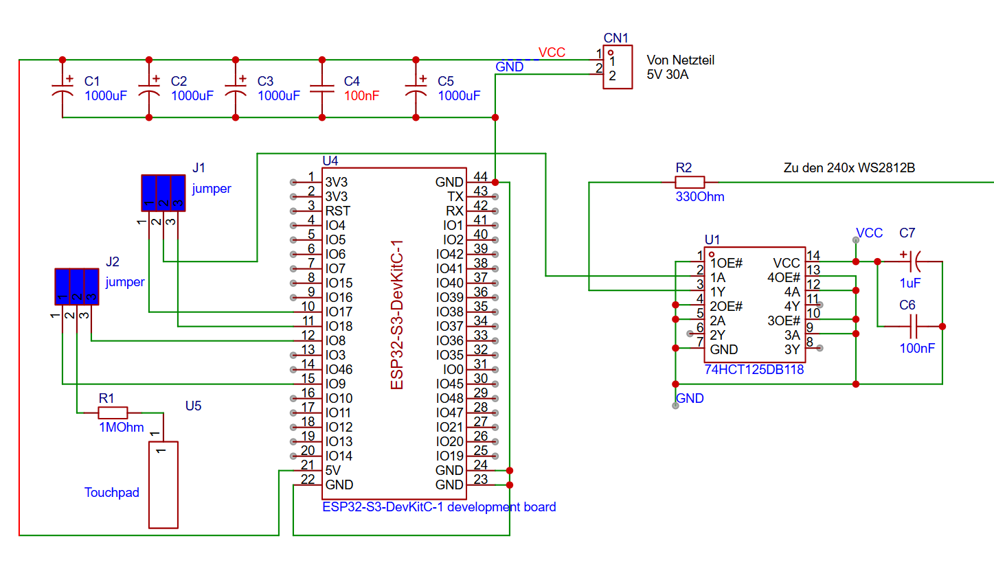
Bild
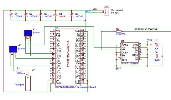
C1 1000uF C2 1000uF C3 1000uF C4 100nF C5 1000uF CN1 1 2 VCC GND 5V 30A J1 jumper J2 jumper R2 330Ohm Zu den 240x WS2812B U4 ESP 32 -S 3-DevKitC-1 1 3V3 2 3V3 3 RST 4 IO4 5 IO5 6 IO6 7 IO7 8 IO5 9 IO6 10 IO7 11 IO8
in
„ESP32 und 240Stück WS2812B“
·
Mikrocontroller und Digitale Elektronik
·
23.12.2025 17:04
·
Schaltpläne
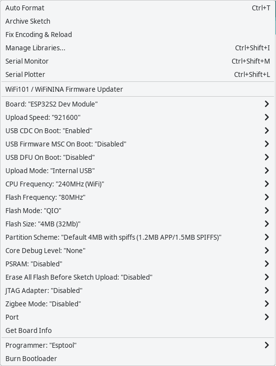
Bild
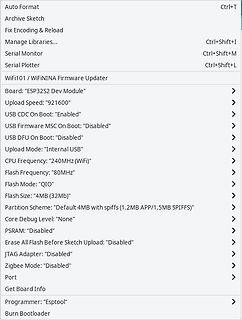
Serial Monitor Ctrl+Shift+M
Serial Plotter Ctrl+Shift+L
WiFi101 / WiFiNINA Firmware Updater
Board: "ESP 32 S 2 Dev Module"
Upload Speed: "921600"
USB CDC On Boot: "Enabled"
USB Firmware MSC On Boot: "Disabled"
USB DFU On Boot: "Disabled"
Upload Mode: "Internal USB"
CPU Frequency: "240MHz (WiFi)"
Flash Frequency: "80MHz"
Flash Mode: "QIO"
Flash Size: "4MB (32 Mb)"
Partition Scheme: "Default 4MB with spiFFS (1.2 MB APP/1.5MB SPIFFS)"
Core Debug Level: "None"
PSRAM: "Disabled"
Erase All Flash Before Sketch Upload: "Disabled"
JTAG Adapter: "Disabled"
Zigbee Mode
in
„Sammelbestellung AR488 kompatibler USB-GPIB Adapter. Interesse?“
·
Mikrocontroller und Digitale Elektronik
·
27.04.2025 16:39
·
Screenshots
| Rücklicht 12V | Bremslicht 0V | GND 1N4007 DC/DC Wandler 5V IN + OUT + 1N4007 IN - OUT - Relais ESP 32 Stecker S NO 3V3 GND + COM Rück DC/DC Wandler 3.3V EN G23 - NC Brems GND IN + OUT + SP G22 SN TXD IN - OUT - G34 RXD G35 G21 G32 GND G33 G19 G25 G18 G26 G5 MPU6050 G27 G17 VCC G14 G16 GND G4 G12 SCL GND G0 SDA G13 G2 XDA SD2 G15 XCL SD3 SD1 AD0 CMD SD0 INT V5 CLK
in
„Schon der zweiten ESP32 abgeraucht“
·
Fahrzeugelektronik
·
11.01.2024 15:25
12EA 81DD 1AD 21CA S S S S S S S S S S S S S S S S S 12DA 91DD 2 AD 31FA V V V V V V V V V V V V V V V V V TC223C080AF-101(ESP 4) 22FA 02DD 3AD 31DA 2 22EA 12DD 4AD 31CA 6 1 2 2 3 4 5 6 7 8 8 9 0 1 2 3 4 0 32 FA 22DD 5AD 41FA
in
„Roland G-70 fährt nicht hoch.“
·
Analoge Elektronik und Schaltungstechnik
·
31.03.2025 00:31
NC NC 28 BA3 23 A3 23 NC NC 27 BA2 24 A2 D +3.3 NC NC BA1 A1 D 3.3 IC80D 4 24 NC NC 26 TP6 25 A0 1 25 NC S S N D +3.3 HD74LV32 AT IC80E V V G TESTLAND1R2 S 1 12 HD74LV32 AT XCSFLASH 26 CE 11 C380 0.1 3 6 6 BXWE0 11 WE VDD 37 13 GRM39@ 1
in
„Roland G-70 fährt nicht hoch.“
·
Analoge Elektronik und Schaltungstechnik
·
26.03.2025 23:19
Verstärker versehen. Die Anschlüsse liegen im RM 2 ,54mm. Weiterhin kommt, wie oben erwähnt, der Si4732 zum Einsatz. Platinen können über DH4YM bezogen werden. (Bild Layout, nicht 1:1) Bauteilliste 1x TTGO ESP 32 S 3 1,9 Zoll 2 x SMA, kleine Ausführung für
in
„Widerstände am I2C“
·
Mikrocontroller und Digitale Elektronik
·
24.12.2024 22:29
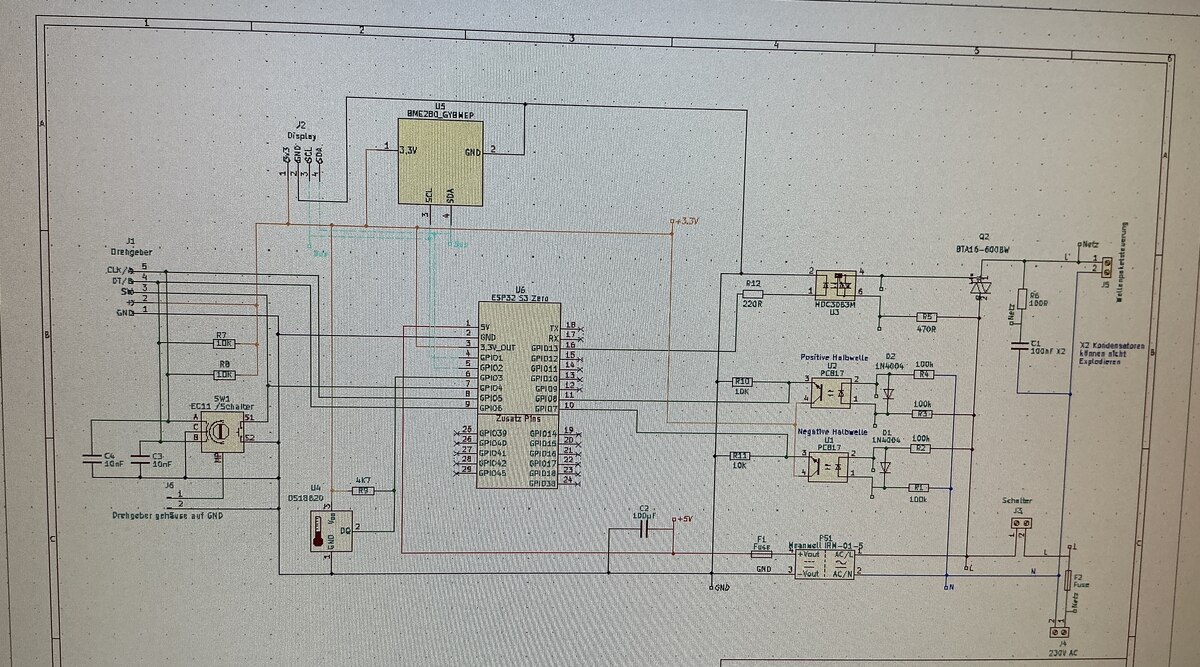
Bild
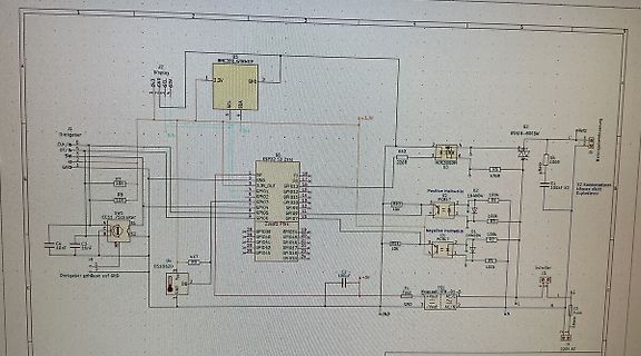
J2 Display 3.3V GND SCL SDA U5 BME280_GYBWEP R7 10R R8 10R SW1 Schalter U6 ESP 32 -S 3 Zeil C4 10uF C3 1gf R9 47R U4 DS18B20 DG 2 R10 220R R12 220R Q2 BTA16-600B U2 Positive Halbwelle IN4004 100k R11 1k R13 100k U3 Negative Halbwelle IN4004 100k R15 10k R14 470R C1 100nF C2 100nF R1 100k R2 100k R3 100k R4 100k R5 100k R6 100k R16 100k R17 100k R18 100k R19 100k R20 100k R21 100k R22 100k R23 100k R24 100k R25 100k R26 100k R27 100k R28 100k R29 100k R30 100k R31 100k R32
in
„ESP32 S3 Zero WLAN Probleme“
·
Mikrocontroller und Digitale Elektronik
·
30.06.2025 17:38
·
Fotos
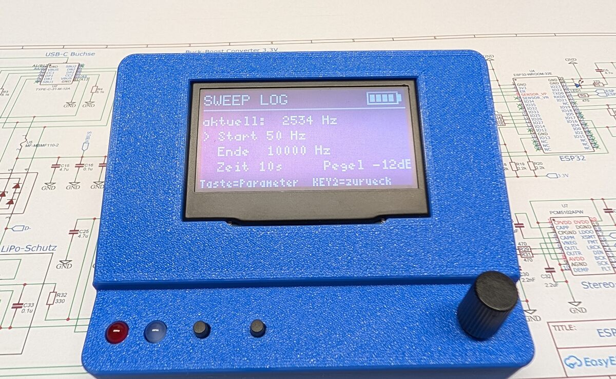
Bild
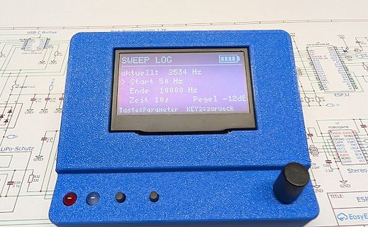
SWEEP LOG
aktuelle: 2534 Hz
> Start 50 Hz
> Ende 10000 Hz
Pegel -12dB
Zeit 10s
Taste=Parameter KEY2 =zurueck
USB-C Buchse
Buck-Boost Converter 3.3V
ESP 32 -WROOM-32 E
LiPo-Schutz
in
„Zeigt her eure Kunstwerke (ab 2023)“
·
Projekte & Code
·
09.10.2026 16:30
·
Fotos
],[] for i in range(4,MAX+1,4): x.append(i//4) # x axis in WORDS z = 14 + 2 *i # 14 cycles addr. setup plus two cycles per byte y.append(84/z*i) # read speed in MB/s #─────[ Tests ]───── cyc = 14 + 2 *4 # for 1WORD (4BYTE) print(f'{84 / cyc * 4:.3f} MB/s ') # 84MHz / cycles * numbytes cyc = 14 + 2 *256 # for 64WORD (256BYTE) print(f'{84 / cyc * 256:.3f} MB/s ') # 84MHz / cycles * numbytes #─────[ Plot ]───── plt.title('sequential forward reads (WORD size)') plt.xlabel('WORDS (32 bit)') plt.ylabel
in
„Micropython Wetterstation“
·
Projekte & Code
·
24.01.2026 15:02
0x0A, 0x0C, 0x0E, 0x10, 0x12, 0x14, 0x16, 0x18, 0x1A, 0x1C, 0x1E, 0x20, 0x22, 0x24, 0x26, 0x28, 0x2 A, 0x2 C, 0x2 E, 0x30, 0x32 , 0x34, 0x36, 0x38, 0x3A, 0x3C, 0x3E, 0x40, 0x42, 0x44, 0x46, 0x48, 0x4A, 0x4C, 0x4E, 0x50, 0x52, 0x54, 0x56, 0x58, 0x5A, 0x5C, 0x5E, 0x60, 0x62, 0x64, 0x66, 0x68, 0x6A, 0x6C,
in
„EMS > ESP8266-12 WLAN-Modul“
·
Haus & Smart Home
·
12.10.2015 16:20
channel, hidden); DEBUG_OUT.printf(PSTR(" %02d: [CH %02d] [%02X:%02X:%02X:%02X:%02X:%02X] %ddBm %c %c %s "), i, channel, bssid[0], bssid[1], bssid[2 ], bssid[3], bssid[4], bssid[5], rssi, (encryptionType == ENC_TYPE_NONE) ? ' ' : '*', hidden ? 'H' : 'V', ssid.c_str()); DEBUG_OUT.println(""); delay(1); boolean
in
„Wechselrichter Hoymiles HM-xxxx 2,4 GhZ Nordic Protokoll?“
·
Mikrocontroller und Digitale Elektronik
·
06.08.2022 20:38
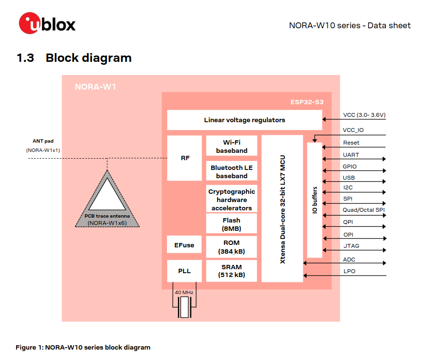
Bild
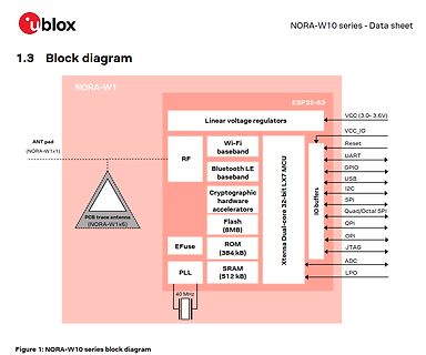
ublox NORA-W10 series - Data sheet 1.3 Block diagram NORA-W1 ESP 32 -S 3 Linear voltage regulators VCC (3.0- 3.6V) ANT pad (NORA-W1x1) RF Wi-Fi baseband Reset UART Bluetooth LE baseband GPIO Xtensa Dual-core 32 -bit LX7 MCU USB I2 C Cryptographic hardware accelerators
in
„Arduino Nano mit ESP32-Prozessor“
·
Mikrocontroller und Digitale Elektronik
·
17.07.2023 22:09
·
Diagramme
Einschalten definiert bleiben. Deshalb würde ich klar den ±12-V-Analogschalter nehmen. Mein konkreter Aufbau ESP 32 / STM32 / AVR │ ├── Timer-PWM 1 kHz ── 1 kΩ ── TMUX6219 SEL ├── ENABLE ─────────── 1 kΩ ── TMUX6219 EN └── ADC ◄── Schutz + Pegelverschiebung ◄── CP isolierter ±12-V-Wandler ├── +12 V ── 100 nF +
in
„saubere Rechtecksignalpegelwandlung 0/5V auf +12/-12V“
·
Mikrocontroller und Digitale Elektronik
·
29.07.2026 22:17

 Bild
 Bild
 Bild
 Bild
 Bild
 Bild
 Bild
 Bild
 Bild
 Bild
 Bild
 Bild
 Bild
 Bild
 Bild