SYMBOL TEST CONDITIONS MIN. TYP. MAX. UNIT Static Drain-Source Breakdown Voltage VDS VGS = 0 V, D = 250 μA 100 - - V VDS Temperature Coefficient ΔVDS/TJ Reference to 25 °C, D = 1 mA - 0.12 - V/°C Gate-Source Threshold Voltage VGS(th) VDS
SOT457 1.4. Quick reference data Table 2. Quick reference data Symbol Parameter Conditions Min Typ Max Unit V EN enable voltage NCR320U - - 25 V NCR321U - - 4.5 V V output voltage - - 16 V out Iout stabilized output current NCR320U V out 1.4 V; [1] 9 10 11 mA V EN= 12 V NCR321U V out 1.4 V; [1] 9 10
<a href="#fn48" class="footnote-ref" id="fnref48" role="doc-noteref"><sup>48</sup></a></p> <h2 id="max-max_y"> Max (max_y) </h2> <p>Softmaker Freeoffice wurde ja schon erwähnt. Momentan gibt es sogar das große Softmaker Office Paket kostenlos, ist aber die Version von 2021. Dennoch sicherlich einen Blick
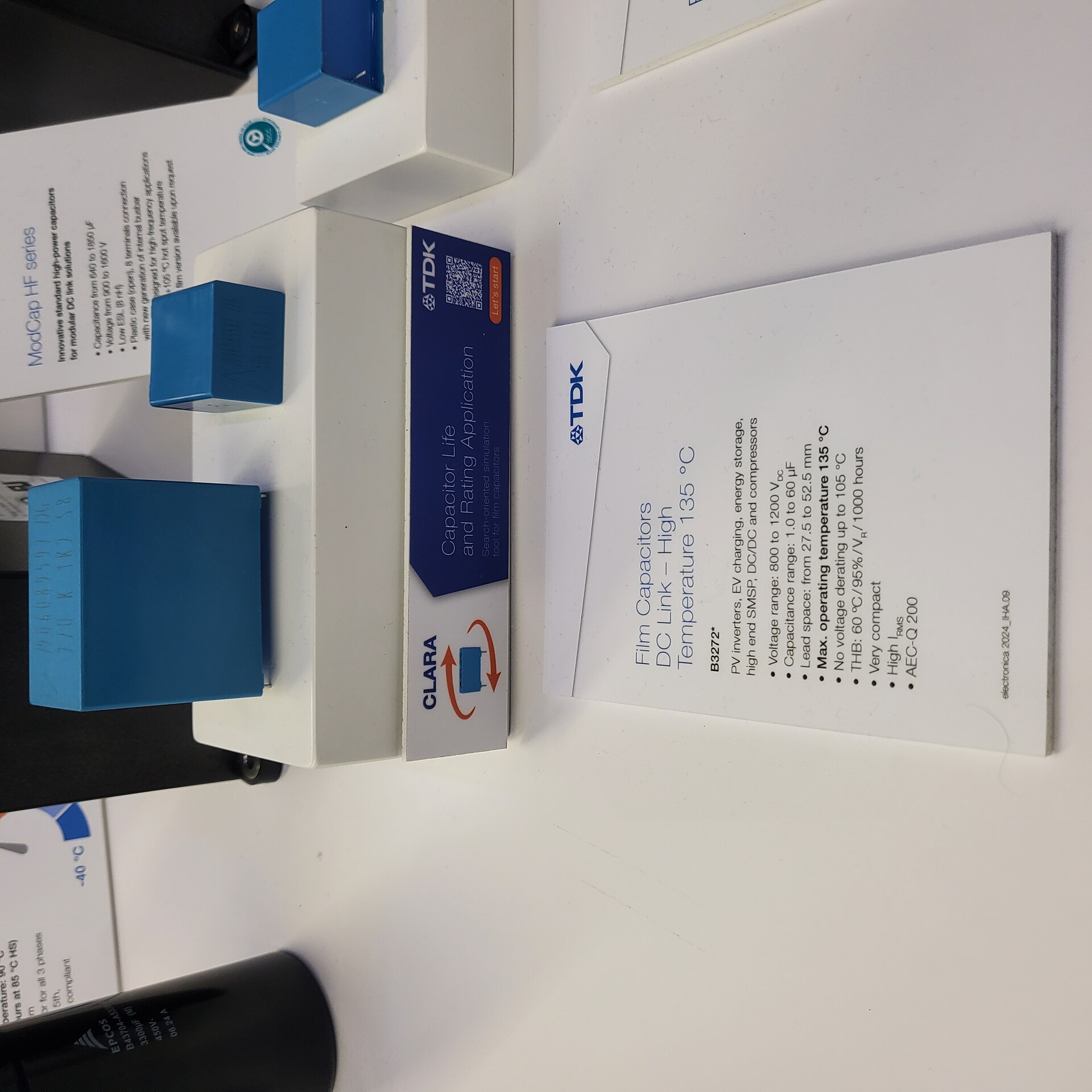
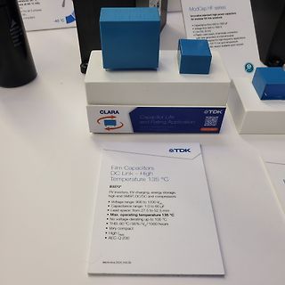
1500 V
Low ESR (B/H)
High current generation of terminal holder
for high-frequency applications
up to 105 °C hot spot temperature
Film version available upon request
CLARA Capacitor Life and Rating Application
TDK
Film Capacitors
DC Link – High Temperature 135 °C
B3272*
PV inverters, EV charging, energy
all the products ◼ Operating Current: 310uA(Typ) needing power factor improvement. The PFC adopts ◼ Max Frequency: 220kHz(RT:220kΩ) boundary conduction mode (BCM), and switching loss ◼ Operating Temperature Range: -40°C to +105°C reduction and noise reduction are possible by Zero Current Detection (ZCD
ein Tischmultimeter. Wichtig wären mir: - Nicht zu tief, es muss auf mein Wandregal passen (max ~ 30cm, gern kürzer. Breite und Höhe sind nicht so das Problem) - Gute Auflösung in kleinen Messbereichen, ich mache recht viel im Bereich <1mA und da wäre es gut, wenn das DMM zuverlässlich zwischen
Johannes F. schrieb im Beitrag #7773191: > Naja, bereits deine Beschränkung auf max. 30 cm Tiefe schließt schon > viele ältere, aber gute Geräte aus, wie das 34401A (ca. 40 cm). 348/379mm
genau ein 150A Model ist oder mehr werde ich ohne Bezeichnung nicht Testen können. Maschine liefert max. 150A Schweißstrom.. Bei gleicher Bauform würde auch eins mit höherem Nennstrom eine Option sein.
Sorry. Hab mich vertan. Meine Module sind im Format 105mmx60mm. Viel zu groß. BSM150GD120 Allerdings halte ich, wenn die Module für die Erzeugung der sekundären Wechselspannung sind, 150A Nennstrom für grenzwertig. Auch wenn diese nicht mit 100% Einschaltdauer
2 7:0 AMAGCNDX AM AGC Index This byte reports the current AGC gain index. 0 = Minimum attenuation (max gain) 1 – 36+ATTN_BACKUP = Intermediate attenuation 37+ATTN_BACKUP = Maximum attenuation (min gain) Note: The max index is subject to change. See Property 0x3705 AM_FRONTEND_AGC_CONTROL for details
shouldered leads (A case) DIMENSIONS in inches [millimeters] H 0.3 mm T MIN. + 12 mm Ø D min. E CASE CODE H MAX. D MAX. T MAX. E ± 0.006 [0.15] Ø 0.002 [0.05] (+10 %) A 0.287 [7.3] 0.185 [4.7] 0.165 [4.2] 0.100 [2.54] 0.020 [0.5] B 0.413 [10.5] 0.287 [7.3] 0.189 [4.8] 0.200 [5.08] 0.020 [0.5] C 0.413 [10.5] 0.484
"100% duty cycle". Aber nach einer Stunde dauersenden (z.B. für RTTY) soll die Sendeleistung auf max. 50W reduziert werden. Ich weiß nur nicht mehr wo ich das gelesen hab, aber vielleicht im Handbuch (also Usemanual).
Rechtsanschlag), also nichtmal ansatzweise die 100W wie es sein soll (lt. Manual auf min. 100W und max. 110W einstellen). Muss man das für FM vielleicht irgendwas extra einstellen? Im Servicemanual steht nix davon... Gruß Flo
/°C 4.1.6 Crystal Oscillator Table 4.6. Crystal Oscillator Parameter Symbol Test Condition Min Typ Max Unit Crystal Frequency fXTAL 0.02 — 30 MHz 4.1.7 External Clock Input Table 4.7. External Clock Input Parameter Symbol Test Condition Min Typ Max Unit External Input CMOS Clock fCMOS 0 — 48 MHz Frequency
0.039to0.043in.) Wave Soldering a, b Manual Solder Dipping Dambar shear- 0.65 mm 0.919 mm Pre-heat Temperature 105°C max. — off area (max.) (0.026 in.) (0.036 in.) Pre-heat Time 60s max. — Lead size (typ.) 0.50 × 0.50 mm 0.707 mm 1.05 to 1.15 mm Peak Temperature 250°C max. 260°C max. (0.020 × 0.020 in.) (0.028 in.) (0.041to0.045in.) Dwell Time 3s max. 5s max. Dambar shear- 0.70 mm 0.99 mm off area (max.) (0.028 in.) (0.039 in.) a. The preceding conditions refer to measurement with a thermocouple mounted at the bottom of the PCB. b. Use only bottom
flashing and stop test. MASK ROM : PIANO 1 LED Flashing MIDI Loop : PIANO 2 E.PIANO2 <*1>LED Flashing <Max Output Level / Distortion Ratio Check> Press [METRONOME] {PIANO2} LED ON Enter this test. Check Max Output level/Distortion Ratio in order of OUTPUT/PHONES1/PHONES2 by pressing [METRONOME]. Acceptable
The maximum allowable continuous power dissipation at any ambient temperature is calculaDed by PTJ(MAX)- Lead Temperature ....................................260C TA/ JA. Exceeding the maximum allowable power dissipation Storage Temperature.............. –65°C to +150C will cause excessive die temperature
37.5A 0 ~ 19.0A 0 ~ 15.0A 0 ~ 12.7A 0 ~ 9.5A Rated Power 450W 456W 450W 457W 456W Ripple & Noise (Max.) Note.2<1% (mVp-p), according to the rated Output Voltage Output Voltage Adj. Range ±10% Typical adjustment by potentiometer Voltage Tolerance Note.3±1.0% Line Regulation ±0.5% Load Regulation ±0.5%
0,65WB+5V Netzpotentail-230Vac M2 Mutter DIN934 SW4 M2 Mutter DIN934 SW4 L 2 D- ws 2 C A B C D USB a max0,2Aout (3x 72mA) Wi1b Lager1 Lager2 Lager 6x10x3 Flansch ID6 AD10/11x3mm MF106ZZ 6,39€/10 Ball Bearing Flange Wi 10,5x10x5x0,5mm vz-21 8x M2x4 DIN84 +8xMutter 1 5V rt 9 N A 5V 60x60x40x2mm vz 5xBL USB-Micro5
(ground = 0 V). Symbol Parameter Conditions 25 °C -40 °C to +85 °C -40 °C to +125 °C Unit Min Typ Max Min Max Min Max VIH HIGH-level V CC = 2.0 V 1.5 1.2 - 1.5 - 1.5 - V input voltage V CC = 4.5 V 3.15 2.4 - 3.15 - 3.15 - V V = 6.0 V 4.2 3.2 - 4.2 - 4.2 - V CC VIL LOW-level V CC = 2.0 V - 0.8 0.5 -
(ground = 0 V). Symbol Parameter Conditions 25 °C -40 °C to +85 °C -40 °C to +125 °C Unit Min Typ Max Min Max Min Max V HIGH-level V = 4.5 V to 5.5 V 2.0 1.6 - 2.0 - 2.0 - V IH CC input voltage V LOW-level V = 4.5 V to 5.5 V - 1.2 0.8 - 0.8 - 0.8 V IL CC input voltage V HIGH-level V = V or V ; V = 4.5
specified. Table 4 DC Characteristics Parameter Symbol Values Unit Note / Test Condition Min. Typ. Max. Operating supply voltage V 4.5 – 60 V – S Operating bias control voltage VB 4.5 – V V recommended to S connect toV S Under Voltage Lock Out V 4.05 4.25 4.45 V IC deactivated1) S, UV, off VS, UV, on
Programming (continued) 1800 1700 1600 1500 A 1400 m - 1300 o 1200 h e 1100 h 1000 t i 900 I L 800 OS(max) t e 700 r 600 C 500 IOS(nom) 400 300 200 OS(min) 100 0 15 25 35 45 55 65 75 85 95 105 115 125 135 145 155 165 175 185 195 205 215 225 235 R ILIM- Current Limit Resistor - kW Figure 23. Current-Limit
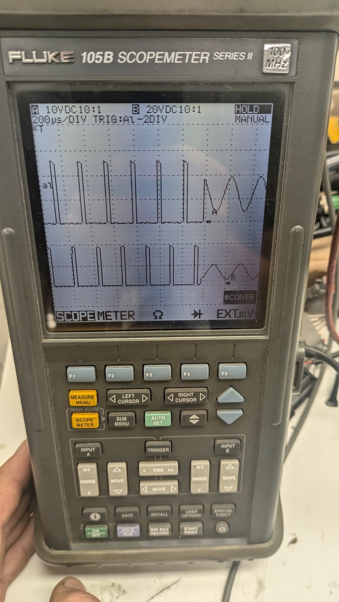
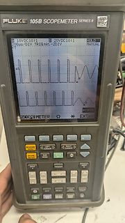
FLUKE 105B SCOPEMETER SERIES II 100 MHZ A 10VDC 10:1 B 20VDC 10:1 HOLD 20us/DIV TRIG:A1-2DIV MANUAL a1 b CONTR SCOPEMETER EXT.mV F1 F2 F3 F4 F5 MEASURE MENU LEFT CURSOR RIGHT CURSOR SUB MENU AUTO SET SCOPE METER
1 1 10 -6 10 -5 10-4 10 -3 10-2 10 -1 1 t (s) t (s) i i AC01 and AC01-AT Pulse on a regular basis; max. permissible AC03 and AC03-AT Pulse on a regular basis; max. permissible peak pulse power ( Pˆ max.) as a function of pulse duration (t ) peak pulse power ( P max.) as a function of pulse duration (
EPX880 & EPX8160: I = 12 mA DC, V = min., 0.2 V OL CCO current Note (4) I Input leakage current V = max., GND < V < V , Note (5) –10 10 A I CCO IN CCO OZ Output leakage current EPX880 & EPX8160: V CCO = max., OUT = VCCO –50 50 A EPX880 & EPX8160: V CCO = max., OUT = GND –100 100 A SC Output short circuit
to +85⋅C,CC = +2.7V to +5.5V,SS = 0V1, 2, 3 16MHz CLOCK VARIABLE CLOCK SYMBOL FIGURE PARAMETER MIN MAX MIN MAX UNIT 1/t 14 Oscillator frequency CLCL Speed versions :S 3.5 16 MHz t 14 ALE pulse width 85 2t –40 ns LHLL CLCL AVLL 14 Address valid to ALE low 22 tCLCL–40 ns LLAX 14 Address hold after ALE
Electrical Characteristics CD4528BM (Note 2) b55§C a 25§C a 125§C Symbol Parameter Conditions Units Min Max Min Typ Max Min Max IDD Quiescent Device CurrentDD e 5V 5 0.005 5 150 mA VDD e 10V 10 0.010 10 300 mA e VDD 15V 20 0.015 20 600 mA V Low Level Output Voltage V e 5V 0.05 0.05 0.05 V OL DD VDD e 10V
value of φ hmax . This idea can be represented by the formula: ▯ µ (B)▯ φh(B) = ef f φhmax (2.7) µef f,max The next entry in the dialog is H .cIf the material is a permanent magnet, you should enter the magnet’s coercivity here in units of Amperes per meter. There are some subtleties involved in defining
hätte wohl besser gehalten. Zugentlastung der 1 mm Lötnaht, nein! Hab jetzt auch USB Lampe mit max 1 Meter Kabel und keine Zugentlastung dran, Kabel sind auf die kleine Platine, dadrauf LED Lämpchen. Dann kein Schalter dran. Jedesmal unterm Schreibtisch kriechen und Stecker ziehen. Bin gespannt wie
sowas: https://www.conrad.de/de/p/tru-components-mjsts-103-3950-1-600-3d-temperatursensor-30-bis-105-c-10-k-3950-k-1570951.html Schneller zum Ziel führt ein Besuch bei Rossmann: https://www.rossmann.de/de/ideenwelt-ideenwelt-best-basics-innen--und-aussenthermometer/p/4305615771267 Dann hat man
+ K C 5 A L I O I 1 M N ] ] M M M E E E E E E E E E E N C O O O O O O O O O O C N M S S P P P M U1 MAX:180mA P O [ [ P P P T X T X T X X X T X P P T X T X T X X X T X V / C I ] / ] WP 12HEADER 3 IN VO 4 O T N N O O O S / 2 / 4 / 6 / 2 / 4 / 6 / 2 / 4 / 6 / 1 / / [ 9 [ O A1 P 5 O O P P PI H N D D D D
/°C 4.1.6 Crystal Oscillator Table 4.6. Crystal Oscillator Parameter Symbol Test Condition Min Typ Max Unit Crystal Frequency fXTAL 0.02 — 30 MHz 4.1.7 External Clock Input Table 4.7. External Clock Input Parameter Symbol Test Condition Min Typ Max Unit External Input CMOS Clock fCMOS 0 — 48 MHz Frequency
aber erheblich größer, und die Richtung stimmt auch. Unterm Strich führen beide Konstrukte zur selben max. Geschwindigkeit, bis auf die mech. Verluste des Magneten selbst.
Uwe S. schrieb im Beitrag #7738133: > Und zwar wird die max. Geschwindigkeit der Kugel beim drehbaren > Magneten sogar etwas geringer sein. Weil am Drehpunkt des Magneten > Reibung entsteht. Warum genau beeinflusst die Reibung des Drehpunktes die Geschwindigkeit
steckbare Schraubklemme Anzeigenjustierung über Werksvorgabe oder direkt am Sensorsignal möglich Min/Max-Speicher mit einstellbarer Permanentdarstellung 30 zusätzliche parametrierbare Stützpunkte Anzeigenblinken bei Grenzwertüberschreitung / Grenzwertunterschreitung Null-Taste zum Auslösen von Hold
Comment 1 V+BATTERY I Power Battery voltage input: High current supply 5.5 V Min. 13.2 V Typ. 32 V Max. 2 GND Power Ground supply 3 GPIO4 I/O CMOS/2X General Purpose Input/output 4 GPIO5 I/O CMOS/2X General Purpose Input/output Warning : Both pin 3 and pin 4 are used by GPIO interface. It is strictly
) DC Output (2080-LC10-12QBB) Attribute Value User supply voltage, min 10V DC User supply voltage, max 26.4V DC On-state voltage drop 1V @ max load current 2.5V @ max surge current Current ratings (each point) 0.5 A @ 55 °C, max 1.0 A @ 30 °C, max 1.0 mA, min Surge current, peak 4.0 A Surge current, max duration 10 ms Controller current 3 A Turn-on- time, max 0.1 ms Turn-off time, max 1.0 ms Relay Outputs (2080-LC10-12AWA, 2080-LC10-12QWB, 2080-LC10-12DWD) Attribute Value Output rating Relay 00 & 01

 Bild
Bild
 Bild
Bild
 Bild
Bild
 Bild
Bild
 Bild
Bild