-
PDF
drm001.pdf
C21 22µF 16V DC C23 10µF 16V DC Semiconductors D1 BAS16 D2 BAS16 D3 BAS16 D4 BAS16 D5 5V1 IC1 MC68HC908JK3 IC2 LM7805 IC3 MAX232 IC4 74HC125D IC5 LM324D Q1 BC818-40 Q2 BC850 Q3 BC850 Q4 BC850 Designer Reference Manual Passive Infrared (PIR) Unit 290 PIR Unit Bill of Materials MOTOROLA PIR Unit Bill
in „AVR ATTiny84A mit C++ Werte an bestimmte Speicherstelle schreiben“ · Mikrocontroller und Digitale Elektronik ·
-
PDF
lcd1.pdf
Command mode. ORLS00 initial state when power is applied, which Now press the E switch (S9) momentarily, 74HC00 4 curiously has the display blanked off, so which ‘‘enables’’ the chip to accept the N.O. 5 6 7 MODULE.D. 0V PIN 6 (’E’) Table 2. The Command Control Codes. Fig. 3. Switch debounce circuit. Here,
in „eigene Zeichen im LCD darstellen“ · Mikrocontroller und Digitale Elektronik ·
-
PDF
how_to_use_cdm_1.pdf
Command mode. ORLS00 initial state when power is applied, which Now press the E switch (S9) momentarily, 74HC00 4 curiously has the display blanked off, so which ‘‘enables’’ the chip to accept the N.O. 5 6 7 MODULE.D. 0V PIN 6 (’E’) Table 2. The Command Control Codes. Fig. 3. Switch debounce circuit. Here,
in „Dokumentation gesucht (UC121902-TNARX-A)“ · Mikrocontroller und Digitale Elektronik ·
-
Datei
main.c
/* * Ratiometric Frequency Counter * * displays 6 digits from 1Hz up to ~40MHz * cycle time 4M/F_CPU ... 16M/F_CPU * theoretical lower frequency limit: F_CPU/16M * theoretical upper frequency limit: 4*F_CPU * * (c) Axel (XL) Schwenke, axel.schwenke@gmx.net * * $Id: main.c 126
in „Frequenzzähler 1Hz - 40MHz“ · Mikrocontroller und Digitale Elektronik ·
-
PDF
ad420_datasheet.pdf
Table Temperature Max Operating Package Inputs Model Range Voltage Options* Range Range AD420AN-32 –40°C to +85°C 32 V N-24 CLEAR Select 2 Select 1 Operation AD420AR-32 –40°C to +85°C 32 V R-24 0 X X Normal Operation *N = Plastic DIP, R = Plastic SOIC. 1 X X Output at Bottom of Span PIN DESIGNATIONS X
in „Suche AD420 in SMD Format“ · Mikrocontroller und Digitale Elektronik ·
-
PDF
LT1161.pdf
Supply Transients G ADD FOR FAULT DETECTION The LT1161 is 100% tested and guaranteed to be safe 1/4 MM74HC266A + fromdamagewith60VappliedbetweentheV andground 100k LOAD pins. However, when this voltage is exceeded, even for a 1161 F08 fewmicroseconds,theresultcanbeacatastrophicfailure. For this reason it
in „Erfahrungen mit LT1161“ · Mikrocontroller und Digitale Elektronik ·
-
PDF
Interfacing_the_Serial_RS232_Port.pdf
Q7 900 BPS 1200 BPS Q8 450 BPS 600 BPS Q9 225 BPS 300 BPS Figure 10 : Baud Rate Generator using a 74HC4060 Table 19 : Possible Baud Rates using a 74HC4060 The 1.8432 Mhz crystal gives some unfamiliar Baud Rates. While many of these won't be accepted by terminal programs or some hardware, they are still
in „fehlerfreie UART-Übertragung?“ · Mikrocontroller und Digitale Elektronik ·
-
PDF
512020-sp-01-en-Switching_Power_Supply_DPS-4005PFC.pdf
LD867.239.2FQA VCC VCC VCC C19 C40 C20 C41 C15 C39 0.1µF 0.1µF 0.1µF 0.1µF 0.1µF 0.1µF GND GND N2 GND N4 N5 X17 31 39 AD0 AD0 3 2 10 1 9 EA AD0 38 AD1 AD1 4 D0 Q0 5 9 A0 2 RST AD1 37 AD2 AD2 7 D1 Q1 6 8 A1 3 AD2 D2 Q2 A2 RS232 C17 AD3
-
PDF
AD9857.pdf
VCC W2 CONNECTION K RESET L C GND W11 D CIC TEST POINT DPD J8 PARALLEL PORT DVDD W12 GND U1 VCC P1 74HC574 AVDD 1 1 20 OUT_EN VCC 2 2 D0 Q0 19 C20 3 3 18 VCC 80 79 78 77 76 75 74 73 72 71 70 69 68 67 66 65 64 63 62 61 0.01µF 4 4 D1 Q1 17 E D D D D D D D D D D L K T D D D K K D R4 D2 Q2 L U N N N D D D N N N F C E P N D L L N 5 5 D3 Q3 16 U2 B / G G G V V V G G G V O E D G V F F G 1.3kΩ 6 6 15 SN74HC14 U3 N L D D D D D D D D D O _L R A A E E A VCC D4 Q4 74HC125 E C _ L R R 7 7 D5 Q5 14 1 1A VCC 14 T O I P 8 8 D6 Q6 13 2 6A 13 1 14 P C 9 9 12 3 1Y 12 RBE 2 EN1VCC 13 D13 1 D13 DIFF_CLKEN 60 W6 D7
in „Updatepin zur Aktivierung beschriebener Kontrollregister“ · Mikrocontroller und Digitale Elektronik ·
-
PDF
AD9857.pdf
VCC W2 CONNECTION K RESET L C GND W11 D CIC TEST POINT DPD J8 PARALLEL PORT DVDD W12 GND U1 VCC P1 74HC574 AVDD 1 1 20 OUT_EN VCC 2 2 D0 Q0 19 C20 3 3 18 VCC 80 79 78 77 76 75 74 73 72 71 70 69 68 67 66 65 64 63 62 61 0.01µF 4 4 D1 Q1 17 E D D D D D D D D D D L K T D D D K K D R4 D2 Q2 L U N N N D D D N N N F C E P N D L L N 5 5 D3 Q3 16 U2 B / G G G V V V G G G V O E D G V F F G 1.3kΩ 6 6 15 SN74HC14 U3 N L D D D D D D D D D O _L R A A E E A VCC D4 Q4 74HC125 E C _ L R R 7 7 D5 Q5 14 1 1A VCC 14 T O I P 8 8 D6 Q6 13 2 6A 13 1 14 P C 9 9 12 3 1Y 12 RBE 2 EN1VCC 13 D13 1 D13 DIFF_CLKEN 60 W6 D7
in „Mit MSP430F2013 parallele Datenübertragung programmieren“ · Mikrocontroller und Digitale Elektronik ·
-
Datei
EMS_Adapter.xml
AQ8OarNeWTFie7QJheLt2k/DcUgcv9cT+2ezRda4O2s0yyQ6TWRYZe3nUhcTB/SFByNJD7ZtEBvhJ13ChSZQt0NeM2wvURnu5Oycrf40eatmRwk4lfMTjQnpB7jYrP74+RCdtiMlS6KqjRKsoS/z24thEhFkFcebPMgbE8rapDLKy72e2VVAGJ3vw50aqbfas/O2GKth9UBca2KnvmxqRrC65crR8cvuM2jdDZn5ufTUuPYsyGZTXYjoEaCYQuKKyZO79oX0V6ZR1z8ZdH+eNEnECc2yuh+owuaL6zpgV0Ne4ujXb055q
-
PDF
AD5415.pdf
1.8pF 80 –1.70 ) ( –1.71 E G ) 60 MCLK = 200kHz T –1.72 B L ( V VDD = 3V R MCLK = 0.5MHz T –1.73 F U S 40 P VDD = 5V U –1.74 O V DD= 3V –1.75 20 TA= 25°C –1.76 VREF = 3.5V 800 TO 7FFH AD8038 AMPLIFIER –1.77 9 0 2 - - 0 20 40 60 80 100 120 140 160 180 200 1 0 20 40 60 80 100 120 140 160 180 200 1 4 4 TIME
in „D/A mit Stromausgang“ · Mikrocontroller und Digitale Elektronik ·
-
PDF
BettyHHU.pdf
/CS2 X1 Y 0R R43 DISP_CS 30 P326/CS1 1 1 GND;40,41,42,43,44 AMB_WE 29 T C8 Q_HC49/S_SMD 1C7 NA 1% AMP-2-767004-2 P327/WE I 1 22PF inner hole for the GROUND BUS must be connected to GND NC 28 P328/BLS3/AIN7 22PF 5% NC 5% 27 P329/BLS2/AIN6 NC;22 135
in „Innenleben von Betty TV“ · Mikrocontroller und Digitale Elektronik ·
-
PDF
2_08.pdf
Zeile 4.Zeile d 1x8 $00-$07 r 1x16 $00-$0F MUX 1:8 n $00-$07 MUX 1:16 (linke Hälfte) g 1x16(8+8) o $40-$47 (rechte Hälfte) w 1x20 $00-$13 e 1x40 $00-$27 r 2x8 $00-$07 $40-$47 c 2x12 $00-$0B $40-$4B i 2x16 $00-$0F $40-$4F t 2x20 $00-$13 $40-$53 m v 2x24 $00-$17 $40-$57 r 2x40 $00-$27 $40-$67 e 4x16 $00
in „Problem LCD 2x8 Zeichen“ · Mikrocontroller und Digitale Elektronik ·
-
PDF
Anleitung.pdf
www.reichelt.de/ 1 Dioden 1N4148 D1 1N 4148 www.reichelt.de/ 1 Dioden 1N4001 D2 1N 4001 www.reichelt.de/ 1 74HC(T)244 oder 40244 IC1 74HC 244 www.reichelt.de/ 1 MAX232 IC2 MAX 232 CPE www.reichelt.de/ 1 Spannungsregler 7805 IC3 µA 7805 www.reichelt.de/ 1 Brückentreiber 293D IC4 L 293 D www.reichelt.de/ 1 Controller
in „AVR_Ctrl mit BasCom programmieren“ · Mikrocontroller und Digitale Elektronik ·
-
 Bild
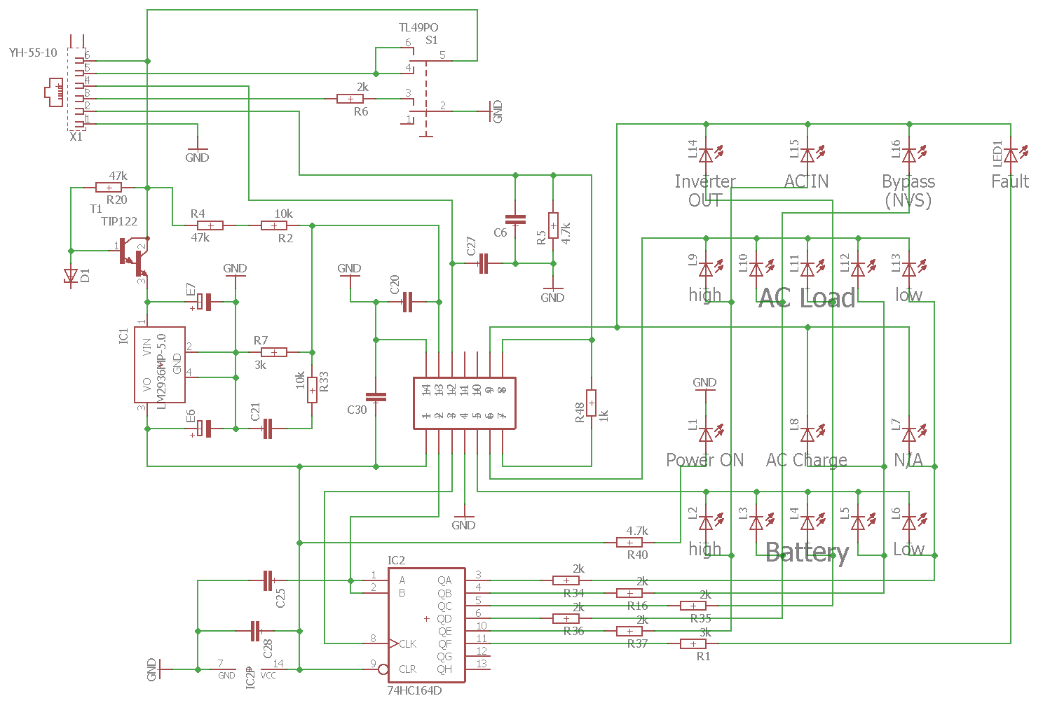
Schaltplan einer Ladeschaltung mit Mikrocontroller
L5, L6, high, AC Load, low, Power ON, AC Charge, N/A, high, Battery, Low, C25, C28, IC2P, CLK, CLR, 74HC164D, R40, 4.7k, R34, 2k, R16, R35, R36, R37, R1, QA, QB, QC, QD
in „Benötige Hilfe beim Identifizieren von Datensignal (Reverse engineering)“ · Mikrocontroller und Digitale Elektronik · · Schaltpläne
-
Datei
oe2chl.txt
.<.@.....| 000022a0 f1 b4 18 00 40 01 e4 f0 a3 d1 f1 b4 3c 00 40 01 |....@.......<.@.| 000022b0 e4 f0 a3 e4 f0 a3 f0 a3 74 0b f0 a3 74 1e f0 a3 |........t...t...| 000022c0 d1 f1 b4 64 00 40 02 74 05 f0 a3 7a 07 7c 00 e2 |...d.@.t...z.
in „LED Laufschrift Software“ · Mikrocontroller und Digitale Elektronik ·
-
PDF
LC-R123R4PG.pdf
. 0CA c hc20.2e 6Ce460 è TèmpTemperature: 5°C(77°F) 6.046.ye ay a( a 02.00C2.00CA e ee r 2ar80 ` Ch`rgChargevoltage: 14.7V(22.8.0ceet)Be Ci 40C240 3.00C3.00CA a rr h 4qh240 CharChargecurrentt: 0.40CA 4.024.ao t
in „Autoradio mit externem Netzteil +Pufferakku sowie ladegerät für Akku.“ · Analoge Elektronik und Schaltungstechnik ·
-
Datei
LED_CUBE.txt
Pin connected to ST_CP of 74HC595 //--- Gelbe Leitung RCK int latchPin = 10; //--- Pin connected to SH_CP of 74HC595 //--- Schwarze Leitung SCK int clockPin = 13; //--- Pin connected to DS of 74HC595 //--- Lila Leitung SI int dataPin
in „LED-Cube Effekte weiter per Knopfdruck“ · Mikrocontroller und Digitale Elektronik ·
-
Datei
Cube_Gro_.ino
AXIS_Z 3 #define BUTTON_PIN 14 #define TOTAL_EFFECTS 17 //--- Pin connected to ST_CP of 74HC595 //--- Gelbe Leitung RCK int latchPin = 10; //--- Pin connected to SH_CP of 74HC595 //--- Schwarze Leitung SCK int clockPin = 13; //--- Pin connected to DS of 74HC595 //--- Lila Leitung SI int dataPin
in „LED-Cube Effekte weiter per Knopfdruck“ · Mikrocontroller und Digitale Elektronik ·
-
PDF
Support-Schematic.PDF
H2 H PIIC307 PIP201010 9 PIP209 Computer1 Cable2 3.3V Iope11 1 2 Iope12 5V 5V Ial2011 2 Iale02 5V SN74HC595 Header 5X2 CHESS-RESERVED Iope13 3 4 Iope14 5V 5V PICabl3203 4 PICable2045V GND 5V GND SCR-RESERVED Iope15 5 6 Iope16 GND 3.3V PICabl5205 6 PICable2063.3V R2 I1 31 R1 P1 SCR-RS Iope17 Iope181-8
in „Zufällige Ausgangsspannungen bei TXB0108PWR“ · Mikrocontroller und Digitale Elektronik ·
-
PDF
TFH-Board_ONE_-_Sys-Doku_-_V2-3.pdf
2,5 1N4148 D3 Gleichrichterdiode 1 DO35-10 Batterie G1 3V, stehend 1 CR2032V Quarz Q1 11,0592 MHz 1 HC18U-V Quarz Q2 3,686 MHz 1 HC18U-V Sicherungshalter Für F1 SH22,5 1 RM 22,5 Feinsicherung F1 0,63A, flink 1 5mmx20mm Print-Taster T1, T2 Schließer 2 6mm x 6mm Präzisionssockel für IC12 DIL 8 1 DIL 8 Präzisionssockel
-
PDF
CSTCW-Series.pdf
TEMPERATURE VARIATION ▯▯ W0.5 CSTCC2.00MG W0.5 CSTCV12.0MTJ ) % ) f ( h i S h c y n c u e q 0 q r Y40 0 40 80 120 r 0 g F Y40 0 40 80 120 i g a Temperature (D) t Temperature (D) i l s c O O Y0.5 Y0.5 W0.5 CSTCC4.00MG W0.5 CSTCW3386MX01 ) ) ( t i i h S S y c n e e u q 0 e 0 r Y40 0 40 80 120 F Y40 0 40
in „AVR+interner RC Oszillator extrem ungenau“ · Mikrocontroller und Digitale Elektronik ·
-
PDF
CSTCW-Series.pdf
TEMPERATURE VARIATION ▯▯ W0.5 CSTCC2.00MG W0.5 CSTCV12.0MTJ ) % ) f ( h i S h c y n c u e q 0 q r Y40 0 40 80 120 r 0 g F Y40 0 40 80 120 i g a Temperature (D) t Temperature (D) i l s c O O Y0.5 Y0.5 W0.5 CSTCC4.00MG W0.5 CSTCW3386MX01 ) ) ( t i i h S S y c n e e u q 0 e 0 r Y40 0 40 80 120 F Y40 0 40
in „Resonatoren“ · Mikrocontroller und Digitale Elektronik ·
-
PDF
Panasonic_JD_700_800_Series_Service_Manual_1_.pdf
JDB40M 2L M5L8257P LSI 4L M74LS04P Ie 6L M74LS20P " BL SN7400N " 10L P80B5A-2 LSI 12L SN74367AN Ie 13L M74LS04P " 7 ·2 3 SBCV3 (4/10)·. L OC. PART NO. PART NAME & DESCRIPTION REMARKS 14L M74LS32P IC 15L M74LS259P
in „Heidenhain Monitor BE 212 für TNC 351“ · Analoge Elektronik und Schaltungstechnik ·
-
PDF
RXV667.pdf
3 3 6 4 100 31 5 3 2 1 1 1 1 30 4 76 RX-V667/HTR-6063/RX-A700 • ICs R X V SiI9134CTU SiI9185ACTU SN74LV4051APWR SN74LVC1G17DCKR R 6 X 7 75 51 A H 7 T 60 41 0 R 76 50 0 6 61 40 / 4 8 5 16 3 80 21 1 100 26 1 1 20 1 25 SN74LVC245APWR TC74HC4051AFEL TC74HC4053AF TC74VHC08FT TC74VHC86FT (EL) TC74VHCT08AFT
in „Yamaha RX-V667 Reparatur und Bezugsquellen?“ · Analoge Elektronik und Schaltungstechnik ·
-
PDF
AVR_Stamp_V1_0_sheet.pdf
PC1 PA2 34 A3 A3 5 3D 3Q 16 A11 B D4 12 12 A9 A6 D3 22 PC2 PA3 33 A4 A4 6 4D 4Q 15 A12 D5 13 13 A10 74HC00D D4 PC3 PA4 A5 A5 5D 5Q A13 D6 14 14 A11 23 PC4 PA5 32 7 6D 6Q 14 D7 15 15 A12 2 D5 24 PC5 PA6 31 A6 A6 8 7D 7Q 13 A14 A13 3 D6 25 PC6 PA7 30 A7 A7 9 8D 8Q 12 A15 16 16 1 D7 26 17 17 A14 IC2A PC7 40 11 18 18 A15 IORQ PB0 41 SCL/2.5C LATCH 1 C 19 19 A16 PB1 SDA/2.5C OC 20 20 A17 PB2 42 MREQ 21 21 A18 PB3 43 BUSREQ PB4 44 SDSEL/2.4A 74HCT573D 22 22 1 23 23 ZRESET PB5 2 MOSI/2.4B 24 24 BUSREQ PB6 MISO
in „Z180-Stamp Modul“ · Mikrocontroller und Digitale Elektronik ·
-
PDF
3dstep_doku.pdf
24 BYV27/200 D-15 DIODE D[1..24] 6 0,47R/2Watt! L<=18mm RESISTOR R1,R2,R6,R7,R11,R12 1 CD4073 DIL14 40XX IC7(CMOS-Reihe) 1 CD4572 DIL16 45XX IC8(CMOS-Reihe) 1 74573 DIL20 74XX IC9(74HC,74HCT,74LS,...nachbelieben) 1 LM324N DIL14 LINEAR U1 3 L297 DIL-20 STEP-IC IC1,IC3,IC5 3 L298 MTIWATT STEP-IC IC2,IC4
in „IC für Schrittmotor“ · Mikrocontroller und Digitale Elektronik ·
-
PDF
3dstep_doku_1_.pdf
24 BYV27/200 D-15 DIODE D[1..24] 6 0,47R/2Watt! L<=18mm RESISTOR R1,R2,R6,R7,R11,R12 1 CD4073 DIL14 40XX IC7(CMOS-Reihe) 1 CD4572 DIL16 45XX IC8(CMOS-Reihe) 1 74573 DIL20 74XX IC9(74HC,74HCT,74LS,...nachbelieben) 1 LM324N DIL14 LINEAR U1 3 L297 DIL-20 STEP-IC IC1,IC3,IC5 3 L298 MTIWATT STEP-IC IC2,IC4
in „Drehmoment des Schrittmotors zu niedrig“ · Mikrocontroller und Digitale Elektronik ·
-
PDF
2_20.pdf
Zeile 4.Zeile d 1x8 $00-$07 r 1x16 $00-$0F MUX 1:8 n $00-$07 MUX 1:16 (linke Hälfte) g 1x16(8+8) o $40-$47 (rechte Hälfte) w 1x20 $00-$13 e 1x40 $00-$27 r 2x8 $00-$07 $40-$47 c 2x12 $00-$0B $40-$4B i 2x16 $00-$0F $40-$4F t 2x20 $00-$13 $40-$53 m v 2x24 $00-$17 $40-$57 r 2x40 $00-$27 $40-$67 e 4x16 $00
in „Brauche Hilfe beim Schaltplan eines LCDs“ · Mikrocontroller und Digitale Elektronik ·
-
PDF
Weidezaun_S03_4093.pdf
Solar- 2 ( - ( A 0 SS14 1 2 3 Terminal Plug Set 15EDG 2,54mm 4A 125V AWG26-18 0,129-0,823qmm PA66 -40/105°C B8,1mm 2,83€/5 A S +Ub 1ND SS14 40V 1A SMA 0,2V GND Oese1-2 M3x16 DIN84 verzinkt Kernloch 2,1mm x € LM2936ZEP-5,0 TO92 40V 50mA@0,2V 20uA >17,3V@18mA 10uF +LEDrd D6 R10 10000uF 16V 16x30 2PC 2,80
in „Weidezaun gegen Schnecken mit Netztrafo und Rohr DN160 für Hobbygärtner“ · Projekte & Code ·
-
PDF
AD9834.pdf
the 68HC11/68L11 microcontroller. The microcontroller is intothedevice.Theserialclockcanhaveafrequencyof40MHz configured as the master by setting Bit MSTR in the SPCR to 1, maximum.Theserialclockcanbecontinuous
in „AD8934 - DDS SPI Ansteuerung“ · Mikrocontroller und Digitale Elektronik ·
-
PDF
Datasheet.pdf
2.Zeile 3.Zeile 4.Zeile 1x8 $00-$07 1x16 $00-$0F MUX1:8 $00-$07 MUX1:16 (linke Hälfte) 1x16(8+8) $40-$47 (rechte Hälfte) 1x20 $00-$13 1x40 $00-$27 2x8 $00-$07 $40-$47 2x12 $00-$0B $40-$4B 2x16 $00-$0F $40-$4F 2x20 $00-$13 $40-$53 2x24 $00-$17 $40-$57 2x40 $00-$27 $40-$67 4x16 $00-$0F $40-$4F $10-$1F
in „LCD Display - 80C537“ · Mikrocontroller und Digitale Elektronik ·
-
PDF
EAS.pdf
2.Zeile 3.Zeile 4.Zeile 1x8 $00-$07 1x16 $00-$0F MUX1:8 $00-$07 MUX1:16 (linke Hälfte) 1x16(8+8) $40-$47 (rechte Hälfte) 1x20 $00-$13 1x40 $00-$27 2x8 $00-$07 $40-$47 2x12 $00-$0B $40-$4B 2x16 $00-$0F $40-$4F 2x20 $00-$13 $40-$53 2x24 $00-$17 $40-$57 2x40 $00-$27 $40-$67 4x16 $00-$0F $40-$4F $10-$1F
in „Probleme mit EA W162B-N3LW (LCD-Display 2x16)“ · Mikrocontroller und Digitale Elektronik ·
-
PDF
LCD162CBL.pdf
2.Zeile 3.Zeile 4.Zeile 1x8 $00-$07 1x16 $00-$0F MUX1:8 $00-$07 MUX1:16 (linke Hälfte) 1x16(8+8) $40-$47 (rechte Hälfte) 1x20 $00-$13 1x40 $00-$27 2x8 $00-$07 $40-$47 2x12 $00-$0B $40-$4B 2x16 $00-$0F $40-$4F 2x20 $00-$13 $40-$53 2x24 $00-$17 $40-$57 2x40 $00-$27 $40-$67 4x16 $00-$0F $40-$4F $10-$1F
in „[V] 5 mal LCD 2x16 Zeichen, blau (neu, originalverpackt)“ · Markt ·
-
PDF
LCD.pdf
2.Zeile 3.Zeile 4.Zeile 1x8 $00-$07 1x16 $00-$0F MUX1:8 $00-$07 MUX1:16 (linke Hälfte) 1x16(8+8) $40-$47 (rechte Hälfte) 1x20 $00-$13 1x40 $00-$27 2x8 $00-$07 $40-$47 2x12 $00-$0B $40-$4B 2x16 $00-$0F $40-$4F 2x20 $00-$13 $40-$53 2x24 $00-$17 $40-$57 2x40 $00-$27 $40-$67 4x16 $00-$0F $40-$4F $10-$1F
in „Anfänger Problem mit der Beleuchtung vom LCD“ · Mikrocontroller und Digitale Elektronik ·
-
PDF
LCD-Blau_Weis.pdf
2.Zeile 3.Zeile 4.Zeile 1x8 $00-$07 1x16 $00-$0F MUX1:8 $00-$07 MUX1:16 (linke Hälfte) 1x16(8+8) $40-$47 (rechte Hälfte) 1x20 $00-$13 1x40 $00-$27 2x8 $00-$07 $40-$47 2x12 $00-$0B $40-$4B 2x16 $00-$0F $40-$4F 2x20 $00-$13 $40-$53 2x24 $00-$17 $40-$57 2x40 $00-$27 $40-$67 4x16 $00-$0F $40-$4F $10-$1F
in „Mega32 LCD geht nicht“ · Mikrocontroller und Digitale Elektronik ·
-
PDF
SSP_175_OBD_II.pdf
limits contributed to a welcome reduction in the emis- sion values of motor vehicles. 100% 80% 60% 40% 20% 0% 1975 1980 1985 1990 1995 2000 Year 175_002 HC CO NO x Malfunctions and faulty components in the engine management system can lead to a drastic increase in pollutant emission. In view of the technical
in „SRAM auslesen der von einer anderen CPU genutzt wird“ · Fahrzeugelektronik ·
-
 Bild
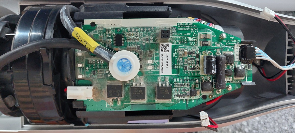
Innenansicht einer bestückten Leiterplatte in einem Gehäuse
PCM Longgood, CN 60104152703, AIH1 7C_2P, V9.1, HC-C-RA87A1, 2019-04-28, LOT/SP195, 2C1014090307, R1, R12, R13, R14, R15, R16, R17, R18, R19, R20, R21, R2, R23, R24, R25, R26, R27, R28, R29, R30, R31, R32, R3, R34, R35, R36, R37, R38, R39, R40, R41,
in „Bosch Athlet 25,2 V Akku 7 Stück Tauschen“ · Analoge Elektronik und Schaltungstechnik · · Platinenfotos
-
PDF
107261_blueline-w_data.pdf
2.Zeile 3.Zeile 4.Zeile 1x8 $00-$07 1x16 $00-$0F MUX1:8 $00-$07 MUX1:16 (linke Hälfte) 1x16(8+8) $40-$47 (rechte Hälfte) 1x20 $00-$13 1x40 $00-$27 2x8 $00-$07 $40-$47 2x12 $00-$0B $40-$4B 2x16 $00-$0F $40-$4F 2x20 $00-$13 $40-$53 2x24 $00-$17 $40-$57 2x40 $00-$27 $40-$67 4x16 $00-$0F $40-$4F $10-$1F
in „[V] 4St. neue LCD 16x2 weiß/blaue Hintergrundbel. LED 9,7mm Char (123x45mm)“ · Markt ·
-
PDF
ATGmeo5c.pdf
34 HC 15,875 4,763 17,907 205,99 228,35 * See Model Number Code, p 14. MOUNTING OPTION NOTES: L Construction = Conduit 2.92 (74,17) connection (1/2 NPSC TAP) MAX. .56 with 14,2 I.D. removable insulating bushing
in „Schrittmotor-Treiber Stepper Motor Pacific Scientific Powermax II“ · Mikrocontroller und Digitale Elektronik ·
-
Datei
flash_dump_20141101_0x01eda2.diff
84 29 42 01 10 02 22 00 28 40 02 00 40 08 00 84 |.)B...".(@..@...| @@ -5430,7 +5452,7 @@ 00015dc0 40 04 00 90 14 00 4c 08 48 60 12 f7 8c 64 3e 29 |@.....L.H`...d>)| 00015dd0 19 b1 14 74 4c ea 42 d2 8d f1 12 42 c7 94 1f 63 |...tL.B
in „Altera FPGA Flash (Active Serial) - Inhalt“ · FPGA, VHDL & Co. ·
-
PDF
User_s_Manual_of_ET-STM32F103.pdf
Board ET-STM32F130 and the circuit that drives LED is connected as Source Current. It uses Buffer No.74HC244 to drive current into LED and then uses signal from Port PB[8..15] to run. In this case, it runs with Logic “1” and stop running with Logic “0”. User can select to ON/OFF operation of Buffer No.74HC244
in „SPI mit SD Karte antwortet nicht korrekt auf CMD0“ · Mikrocontroller und Digitale Elektronik ·
-
PDF
User_s_Manual_of_ET-STM32F103.pdf
Board ET-STM32F130 and the circuit that drives LED is connected as Source Current. It uses Buffer No.74HC244 to drive current into LED and then uses signal from Port PB[8..15] to run. In this case, it runs with Logic “1” and stop running with Logic “0”. User can select to ON/OFF operation of Buffer No.74HC244
in „Suche Schalter“ · Mikrocontroller und Digitale Elektronik ·
-
PDF
ft2232_cable.pdf
1 2 3 4 5 6 7 8 9 F F This simple module does not sense target supply voltage. One could add 74HC125 for DLP2232M U2 CONN1 level translation. 1 SI/WUB ADBUS0/TCK/SK 40 TCK 1 TCK 2 BCBUS3 ADBUS1/TDI/DU 39 TDI 2 TDI E Operation of FT2232 at 2.5V IO voltage 3 38 E is out of spec of 3.0 V minimum.
-
Datei
peps_avr_v12.bas
Werner Römer [werner.roemer@t-online.de] ' ' letzte Änderung ' ' 24.01.2016 Datenbustreiber wieder 74LS241 wg. Timingprobleme ' Unter Wirkbetrieb reicht das Timing nicht aus ' RAM und Treiber mussen noch verbessert werden ' ' 23.01.2016 Adressberechnung eingebaut ' ' Startadresse EPROM ist immer 0000h
in „Suche MOPPEL Projekt in Heft oder .PDF“ · Mikrocontroller und Digitale Elektronik ·
-
PDF
Schematics.pdf
Tune ATT COR 13 MX12 GND S13 16 MX13 D+ D+ D+ D + 3 S14 15 MX14 3 6 9 2 E S15 MX15 S- S- S- S - L 74HC4514 D T3 T5 T6 MUX LED Protection BC817 BC817 BC817 D D V V k k k IC3A 1 . 1 . 1 . 1 R 1GND R 1 GND R 1 GND k 2 A 2 0 B R 1 14 13 C Q MX12 MX11 MX10 15 R/C 3 CLR Q 4 C1 74HC123 100n GND E D D V SV1
-
PDF
Weidezaun_S03_4093.pdf
UVLO=1,98V 100mV A 0 SS14 1 2 3 Terminal Plug Set 15EDG 2,54mm 4A 125V AWG26-18 0,129-0,823qmm PA66 -40/105°C B8,1mm 2,83€/5 3 FB 0,1-1uA EN 4 A S +Ub 1ND SS14 40V 1A SMA 0,2V GND Oese1-2 0,6V 1,5Von/0,4Voff x € LM2936ZEP-5,0 TO92 40V 50mA@0,2V 20uA >17,3V@18mA 10uF +LEDrd D6 R10 10000uF 16V 16x30 2PC
in „Weidezaun gegen Schnecken mit Netztrafo und Rohr DN160 für Hobbygärtner“ · Projekte & Code ·