typ. (A type) 14 ms. typ. (C type) 2.6 ms. typ. (E type) Lead-free, Sn 100%, halogen-free *1 *1. Refer to “ Product Name Structure” for details. 1 STEP-DOWN,PWMCONTROLorPWM/PFMSWITCHABLESWITCHINGREGULATORCONTROLLER S-8520/8521 Series Rev.9.0 _02 Applications On-board power supplies of battery devices
Common V CM 0.8 — 2.5 V Mode Range Input Leakage Current IL Pullups Disabled — < 1.0 — µA *Note: Refer to the USB Specification for timing diagrams and symbol definitions. Rev. 1.8 9 CP2102/9 Table 8. EPROM Electrical Characteristics Parameter Test Condition Min Typ Max Unit CP2109 Voltage on PPwith
790 437 C40 V 100n 50 754 194 C41 E 220µ 35 625 225 F01 Sich T4A 266 553 F02 Sich T4A 326 552 F03 Sich MT315mA 385 552 F04 Sich not used 442 551 R01 D 0R12 5,0 5 1094 96 R02 D 0R12 5,0 5 1138 85 R03 D 0R12 5,0 5 1094 263 R04 D
Confirmation power status PWR? OK OK OK (Response code returned ) 00: Standby Mode (Network OFF) 01: Lamp ON 02: Warmup 03: Cool down 04: Standby Mode (Network ON) 05: Abnormality standby 09: A/V Standby Main Unit Operation Key operation KEY xx N/A OK *Refer the "Key code" OK Projection screen adjustmenttting
Vorwiderstände bei LEDs sein? Ich habe hier folgende LEDs gekauft: https://www.amazon.de/dp/B09FY3VN5Z?ref=ppx_yo2ov_dt_b_product_details&th=1 Spannung LED = 2,9-3,2 V; Spannung mit Vorwiderstand: 12V Stromaufnahme: ca. 20mA, Lichtstärke: 320 mcd Dabei sind ja Vorwiderstände für 12 V. Gemessen habe
Date Rev. No. Changes/Reason of changes Signature 2015-05-08 01 Initial Document KEVIN ZHU 2017-08-18 02 Modified of specification parameter KEVIN ZHU 2018-06-08 03 Modified timetable range KEVIN ZHU 2019-01-18 04 Revision of Specification Format KEVIN ZHU 1 / 18 Document No.: SPC / SK6812RGBP8 Rev. No.
S116S02 Series S216S02 Series IT(rms)≤16A, Zero Cross type S116S02 Series SIP 4pin Triac output SSR S216S02 Series ∗Non-zero cross type is also available. (S116S01 Series/ S216S01 Series) ■ Description ■ Agency approvals/Compliance S116S02 Series and S216S02 Series Solid State 1. Recognized by UL508 (only for S116S02 Series), file Relays (SSR) are an integration of an infrared emitting No. E94758 (as models No. S116S02) diode (IRED), a
https://www.amazon.de/Kerbl-Elektrischer-Schneckenzaun-Schneckenabwehr-Unbedenklich/dp/B0BYS5GJDL/ref=asc_df_B0BYS5GJDL Leider wird die verwendete Spannung nirgends benannt. Bei einem Selbstbau würde ich schon Steckernetzteil mit 24 Volt , >= 0,5A einsetzen. "Schlecht" geklättete Gleichspannung
-Schnittstelle sein soll. Hier das Installationshandbuch: https://www.air-avionics.com/support/02.0200.11E%20VT02INST_rev1.2.pdf Auf Seite 23 steht, dass der GPS-Empfänger nur mit seinem TX-Datenausgang und GND angeschlossen wird, also keine RX-Daten. "GPS data input 4800 bps for ADS-B purposes"
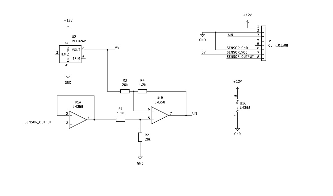
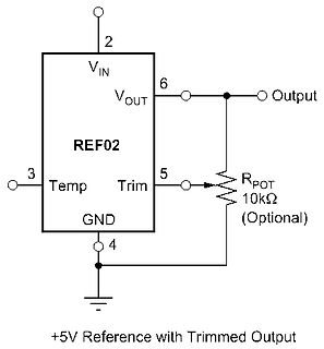
Spannungsabfälle. Für genaue Spannungen zum Messen nimmt man daher Referenzen. Z.B. der bekannte REF02B liefert 4,990V .. 5,010V ganz ohne Abgleich.
Beitrag #7701139: > Für genaue Spannungen zum Messen nimmt man daher Referenzen. Z.B. der > bekannte REF02B liefert 4,990V .. 5,010V ganz ohne Abgleich. "ganz ohne Abgleich" - weshalb mich direkt auf Seite 1 des Datenblattes ein Poti anschaut? Es geht eh an der Frage vorbei: Der TO möchte einen LM317
DDA ≤ VDD3.6V) V SSA Input, analog power supply ground Equivalent to SSanalog power supply ground V REF+ Input, analog reference positive Positive reference voltage used by ADC, 1.8V ≤ REF+ ≤ VDDA V REF- Input, analog reference negative The low/negative reference voltage used by the ADC, REF- = SSA ADCx_IN
/smith-chart/smith-chart-tool-v1 ich verstehe es aber nicht, was muss ich wo eingeben? VSWR=2.96 Ref. Coeff.=0.50 Mag.-1.32 (verschwindet am rechten Bildrand) Phase ?? neuer Versuch https://www.will-kelsey.com/smith_chart/ das fängt mit einer BlackBox an, genauso großes Fragezeichen. Noch eines
gezeichneten Linie in Richtung der Reellen Achse. Mit diesem Serien-C musst du den Admittanz Kreis für 0.02 treffen und machst den Rest mit dem Parallel-C.
to read or write, the key A itself is not readable; key B is data only). For further information refer to Frequently asked questions or Mifare card manual. Remarks Enabled keys are always read as 00 00 00 00 00 00 Using key B as data area will cause a security gap, due to the fact that it is necessary
einer Signalperiode ST 1200/3000 20 µm ca. 0,2 µm MT 60/101 10 µm ca. 0,1 µm MT 1200/2500 2 µm ca. 0,02 µm n u CT 2500/6000 2 µm ca. 0,02 µm i e b s o i o P 12 Alle HEIDENHAIN-Messtaster werden vor der Auslieferung auf ihre Funktion geprüft und die Genauigkeit vermessen. Die Genauigkeit der Messtaster
This material publishing data is a standard measurement example and not a guaranteed value. Please refer as a reference value. There is no previous notice and the design and the specification might be changed. This document is VINATech's proprietary material, and the distribution and the presentation
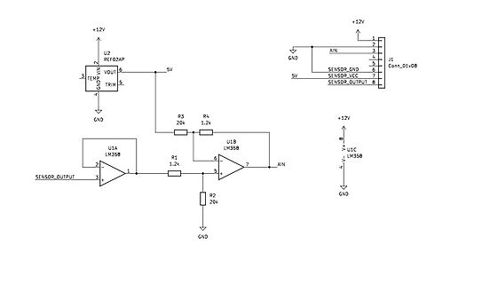
ähnliches Beispiel sehen. Vor allem ist mir noch nicht ersichtlich, weshalb man an die Versorgungsquelle REF02AP verbinbet und wie die Widerstandswerte gewählt wurden... Vielen Dank Grüße L.A.
Hallo Lysandros, ein LM358 hat einen Offset bis zu 7 mV. Die Drift liegt bei 7 µV/°C. Der REF02AP ist eine Präzisionsspannungsquelle. Der LM358 ist einfach zu schlecht für den REF02AP. mfg Klaus
EXCEED 0.25mm (0.010in) PER SIDE. Θ 0 0 8 THERMALLY ENHANCED DIMENSIONS PAD Size E1 D1 90×90E 0.081 REF 0.081 REF 95×13E 0.086 REF 0.117 REF UNIT : INCH * CDT assumes no responsibility for the use of the specification described. CDT reserves the right to modify the product specification without notice
0.58 0.85 0.94 1.11 1.36 1.61 1.87 2.12 2.36 2.50 2.68 3.05 Liquid temperature no subcooling 32°C refer to 101N2100 Instructions for details specifjcations FRCC.PK.047.A2.02 - Manufactured by Secop for Danfoss 77 Hermetic Compressors for DC Voltage BD1.4F-VSD Direct Current Compressor R134a, 12-24V DC
available in unconnectored or connectored • A connector on the fiber is not necessary options. Please refer to the data sheet and the ordering guide for part information. • The plastic fiber is connected by a simple turn of the locking screw Avago offers 1 mm diameter Plastic Optical Fiber (POF) in • The
additional information and design guidance on 5.2.1.1 Choosing Load Capacitors oscillator circuits, refer to these Microchip Application Notes, available at the corporate website C L is the effective load capacitance as seen by the (www.microchip.com): crystal and includes the physical load capacitors,
Motoren montierten Stiften ergibt sich dann eine Art „Raupenbewegung“. ### Microchip Technology WFI32E02UC HPC – ESP32-Alternative mit 60GPIOs Die Armut an GPIO-Pins der ESP32-Varianten bietet Konkurrenten seit jeher Gelegenheit für den einen oder anderen „cheap shot“ - in der Vergangenheit hat sich
hervorgetan, weil man die hauseigenen (und sehr leistungsfähigen) Peripheriegeräte betonte. Mit dem WFI32E02UC HPC steht nun ein an den ESP 32 erinnerndes und auf einem PIC32MZ basierendes Modul am Start, dessen wichtigstes Verkaufsargument - wie in der Abbildung gezeigt - die Verfügbarkeit von insgesamt 60
Billiglötkolbenset von Amazon zurück - gekauft erst im Januar 2024: https://www.amazon.de/gp/product/B09HGS9CXT/ref=ppx_yo_dt_b_search_asin_title?ie=UTF8&psc=1 Erst fiel mir nichts auf, doch irgendwann kam es mir schon komisch vor, dass das Lot so stark glänzt und auch so unproblematisch zu handhaben ist, schon
bleifreies Lot aus? Ja, durchaus. Mit freundlichem Gruß: Bernd Wiebus alias dl1eic http://www.l02.de
docs.flipper.net/bad-usb Alternativ mit anderer Firmware auch per Bluetooth https://thecomputernoob.com/2023/02/17/bluetooth-badusb-attacks-flipper-zero/ Doku zum notwendigen DuckyScript: https://docs.hak5.org/hak5-usb-rubber-ducky/duckyscript-tm-quick-reference
www.amazon.de/Demeras-Injektor-ABS-Kunststoff-Fernbedienung-Computerausr%C3%BCstung-default/dp/B08N5XCX59/ref=sr_1_2 Die haben sogar Wifi. Eigentlich auf der falschen Seite. Aber als HID welches vor dem Einloggen enumeriert werden soll, geht das vermutlich nicht anders als physikalisch am PC vorhanden zu
enable I C-bus and similar bus systems to be extended without degradation of system performance. (Refer to Figure 1 ÒBloc k diagram of PCA9515Ó .) The PCA9515 BiCMOS integrated circuit contains two bidirectional open-drain buffers specifically designed to support the standard low-level-contention arbitration
6 pF *The crystal, traces, and crystal input pins should be isolated from RF generating signals. Refer to Application Note 58: Crystal Considerations for Dallas Real-Time Clocks for additional specifications. CLOCK ACCURACY The accuracy of the clock is dependent upon the accuracy of the crystal and
the Timer/Counter0 Overflow interrupt is executed. The setting of this flag is dependent of the WGM02:0 bit setting. Refer to Table 15-8, ”Waveform Generation mode bit description” on page 111. 2020 Microchip Technology Inc. Data Sheet Complete DS40002070B-page 114 ATmega164A/PA/324A/PA/644A/PA/1284
. > Der Mosfet sitzt links neben dem Roten Kabel unter dem Kondensator. Angesteuert vom HC02, daher LL nötig. Bau doch einfach auch den STS4DF60L ein. Hier eine Auswahl: https://www.tme.eu/de/katalog/multikanaltransistoren_100615/?params=273:1441263;262:1441252;266:1441397,1441251,1441602,1441393,1441573,1441257,1441265,1441380
20Commerical%20Power%20MOSFET%20Obsolescence.pdf "Vishay Siliconix/May 4, 2010" schon lange her. "Refer to Vishay Website for possible alternative products"
the I2C 2002-1A Evaluation Kit http://300pinmsa.org/document/MSA_10G_40G_TRX_ I2C_Public_Document_02_19APR02.pdf So the idea is to look to any general systems that use How To Obtain the New Evaluation Kit dynamic address allocation (even including ones that do 2 not use I C hardware) to find the software
bestellt und heute bekommen. https://www.amazon.de/GAO-EMD201-Dimmer-Adapter-LED-3-200/dp/B072N3FMZY/ref=sr_1_5?dib=eyJ2IjoiMSJ9.sw1gm084_ReDW90tqSE-hpYQD8Hj6yLWigIxdQimK_42LZQiA0_EFLgGE4wvbn8oAgGGsSngCNdk9MeSGd5iB0qaNlv__FC6OU0obHXUd4DDVumJxLF5kDBc53iUuM8UkZWMobQ4J29wepagXI0Y-OT0B4juuSWIDHSz3bO8aQnmHEmZr_NdSwoImkdlLG_p61XCUX5s6JpUC1RUDInoc39EQEV5jTvfXVt02RMqnLyTwvoIDVGgSR5jHrybO9PWcdnrDQmEDJC7Vh6C

 Bild
Bild
 Bild
Bild
 Bild
Bild
 Bild
Bild
 Bild
Bild