-
PDF
CP2102.pdf
CP2102/9 S INGLE -C HIP USB- TO -UART B RIDGE For newer designs, the CP2102N devices offer compatible footprints and are recommended for use instead of the CP2102/9. See the Silicon Labs website (www.silabs.com
in „USB to UART CP2102 Schema“ · Mikrocontroller und Digitale Elektronik ·
-
PDF
CP2102-9.pdf
CP2102/9 S INGLE -C HIP USB- TO -UART B RIDGE For newer designs, the CP2102N devices offer compatible footprints and are recommended for use instead of the CP2102/9. See the Silicon Labs website (www.silabs.com
in „[V] 25St. Silabs CP2102N (QFN24) USB to UART Bridge (10St für 12€)“ · Markt ·
-
PDF
cp2102n-datasheet.pdf
USBXpress™ Family CP2102N Data Sheet The CP2102N devices, part of the USBXpress family, are de- signed to quickly add USB to your applications by eliminating KEY FEATURES firmware complexity and reducing development time.
-
PDF
cp2102n-datasheet.pdf
USBXpress™ Family CP2102N Data Sheet The CP2102N devices, part of the USBXpress family, are de- signed to quickly add USB to your applications by eliminating KEY FEATURES firmware complexity and reducing development time.
in „[V] 10 St. Silabs CP2102N-A01 QFN20 USB-to-UART bridge controller.“ · Markt ·
-
PDF
cp2102n-datasheet.pdf
USBXpress™ Family CP2102N Data Sheet The CP2102N devices, part of the USBXpress family, are de- signed to quickly add USB to your applications by eliminating KEY FEATURES firmware complexity and reducing development time.
in „[V] 10 St. Silabs CP2102N-A01 QFN20 USB-to-UART bridge controller. (10€)“ · Markt ·
-
PDF
cp2102n-datasheet.pdf
USBXpress™ Family CP2102N Data Sheet The CP2102N devices, part of the USBXpress family, are de- signed to quickly add USB to your applications by eliminating KEY FEATURES firmware complexity and reducing development time.
in „[V] 15St. Silabs CP2102N-A01 QFN20 USB-to-UART bridge controller.“ · Markt ·
-
PDF
cp2102n-datasheet.pdf
USBXpress™ Family CP2102N Data Sheet The CP2102N devices, part of the USBXpress family, are de- signed to quickly add USB to your applications by eliminating KEY FEATURES firmware complexity and reducing development time.
in „Frage zu CP2102N und CP2104“ · Mikrocontroller und Digitale Elektronik ·
-
PDF
0900766b8065a805.pdf
required to update the design from RS-232 to USB is to replace the RS-232 level-translator with the CP2102. An evaluation kit for the CP2102 (Part Number: CP2102EK) is available. It includes a CP2102-based USB-to- UART/RS-232 evaluation board, a complete set of VCP device drivers, USB and RS-232 cables,
in „Footprint - USB Uart Bridge“ · Analoge Elektronik und Schaltungstechnik ·
-
PDF
0900766b8065a805.pdf
required to update the design from RS-232 to USB is to replace the RS-232 level-translator with the CP2102. An evaluation kit for the CP2102 (Part Number: CP2102EK) is available. It includes a CP2102-based USB-to- UART/RS-232 evaluation board, a complete set of VCP device drivers, USB and RS-232 cables,
in „DC DC Wandler Pins“ · Analoge Elektronik und Schaltungstechnik ·
-
PDF
0900766b8065a805.pdf
required to update the design from RS-232 to USB is to replace the RS-232 level-translator with the CP2102. An evaluation kit for the CP2102 (Part Number: CP2102EK) is available. It includes a CP2102-based USB-to- UART/RS-232 evaluation board, a complete set of VCP device drivers, USB and RS-232 cables,
in „DC DC Wandler Pins“ · Analoge Elektronik und Schaltungstechnik ·
-
Datei
Code_funktioniert_.txt
include <sys/stat.h> #include <unistd.h> #include <sys/ioctl.h> #include <termios.h> int main() { int cp2102,status; unsigned char bytes_s[255]="Hallo ich bins CP2102!!!", bytes_r[255]; //----------Schnittstelle öffnen-------------------------------- cp2102 = open("/dev/ttyUSB2",O_RDWR); if(cp2102<=0) { perror
in „libusb Problem :[submit_bulk_transfer] submiturb failed error -1 errno=2“ · Softwareentwicklung ·
-
PDF
ICmega8-USB__deutsch_.pdf
Bus des PCs gespeist. Der CP2102 enthalt einen 3.3V – Max I/O Pins: 23 Spannungsregler. Diese 3.3V konnen dem Board durch – Timer: 2x 8Bit, 1x 16Bit das schliessen des Lotjumpers J12 auf der Unterseite des – PWM-Kanale: 3 Boards zuganglich
in „CP2102 und Kurzschluss zwischen Vcc und GND“ · Mikrocontroller und Digitale Elektronik ·
-
PDF
Crumb128-CAN_V5.0-5.1_infosheet.pdf
Processor RAM EEPROM Flash Peripherals Crumb128 V5.0 ATmega128 4kB SRAM 4kB EEPROM 128kB Flash - CP2102 USB-UART converter - mini USB B 5pin connector with RS232 - MAX3221 RS232 transceiver - status LED and tiny reset button Crumb128-CAN AT90CAN128 4kB SRAM 4kB EEPROM 128kB Flash - CP2102 USB-UART converter
in „CAN Bus Kommunikation AT90CAN128, Crumb128-CAN V5.0 AVR CAN Modul“ · Mikrocontroller und Digitale Elektronik ·
-
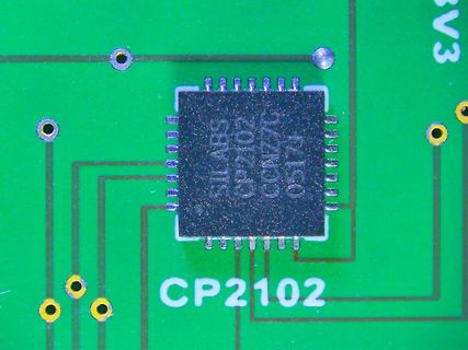
Bild
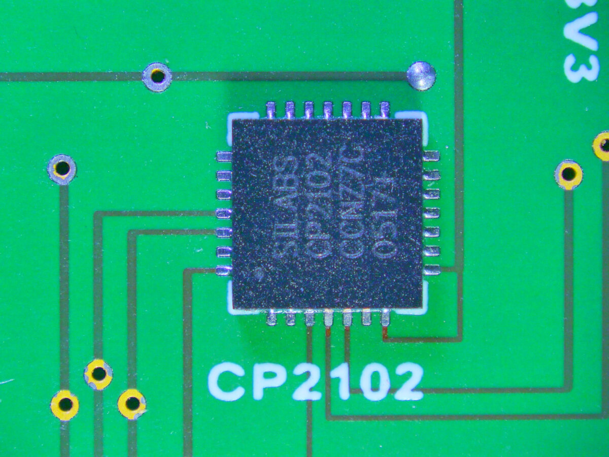
Silabs CP2102 Chip auf Leiterplatte
SILABS CP2102 CCN77C 05171 CP2102 3V3
in „SMD Mikrofon löten Erfahrung, und komisches PCB in Alugehäuse ohne el. Anschlüsse, Smartp galaxy s6“ · Platinen · · Platinenfotos
-
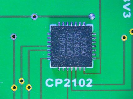
Bild
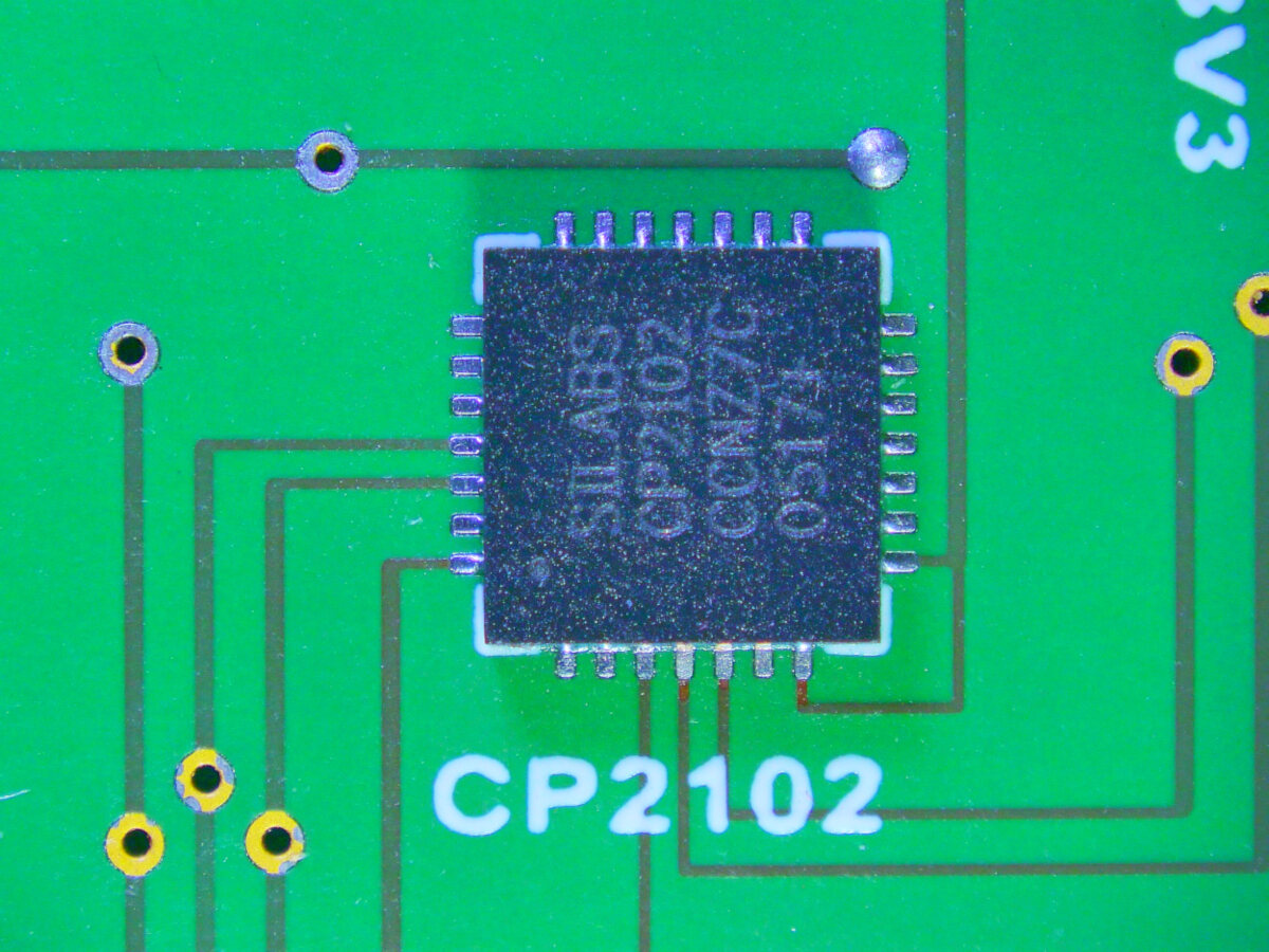
Silabs CP2102 Chip auf Leiterplatte
SILABS CP2102 CCN77C 05171 CP2102 3V3
in „Kann man VQFN mit Heißluft handlöten?“ · Platinen · · Platinenfotos
-
PDF
-
PDF
-
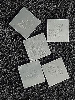
Bild
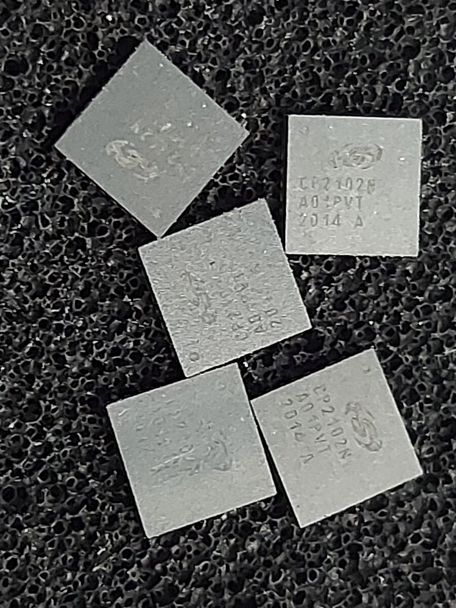
Fünf quadratische Mikrochips auf Schaumstoff
CP2102N A04PVT 2014 A
in „[V] ICs USB Brigdes 8x Silabs CP2105 + 5x CP2102 (15€)“ · Markt · · Fotos
-
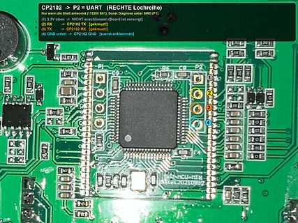
Bild
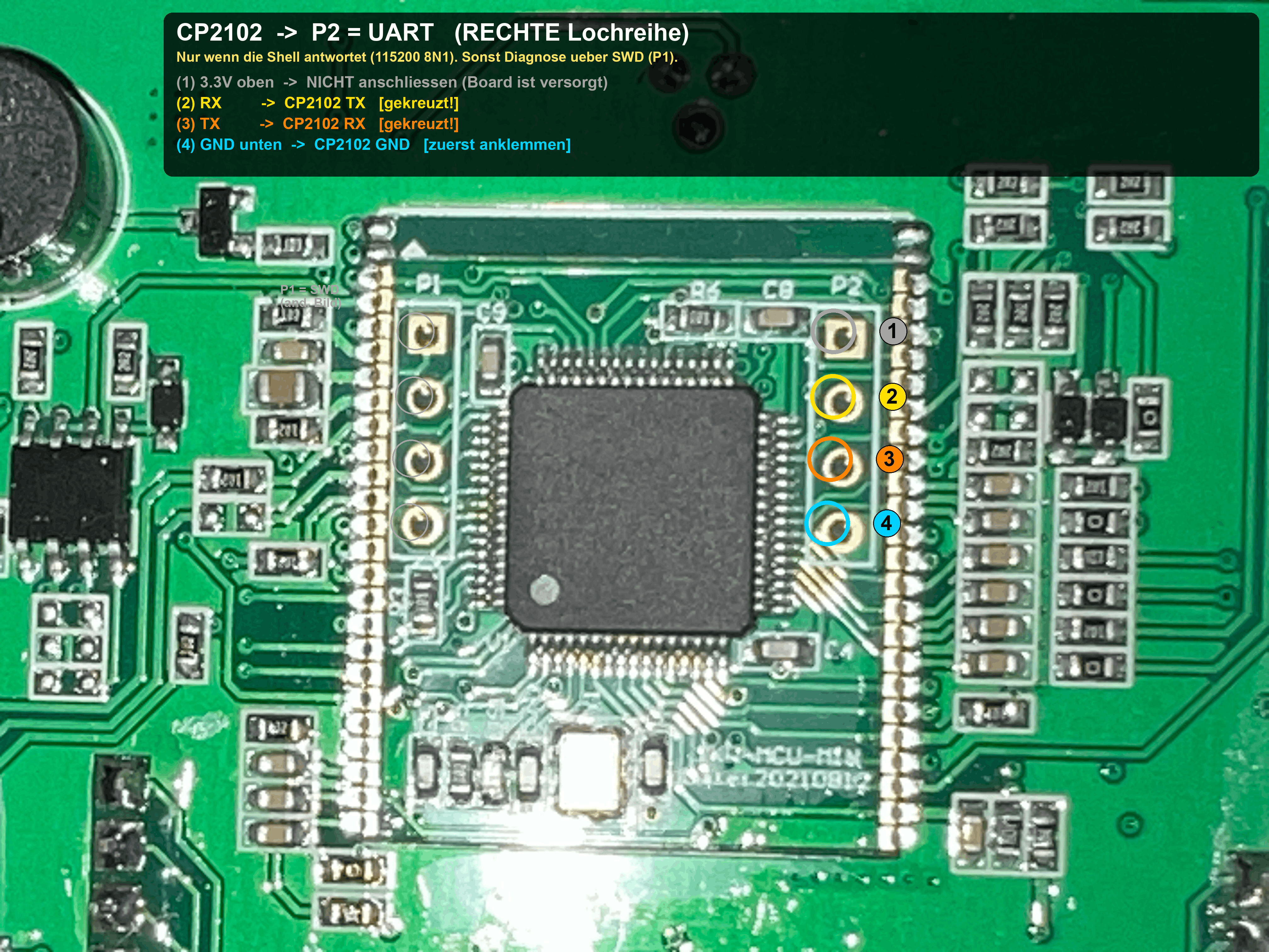
Leiterplatte mit Mikrocontroller und Pinbelegungshinweisen
CP2102 -> P2 = UART (RECHTE Lochreihe) Nur wenn die Shell antwortet (115200 BN1). Sonst Diagnose ueber SWD (P1). (2) RX -> CP2102 TX [gekreuzt] (3) TX -> CP2102 RX [gekreuzt] (4) GND unten -> CP2102 GND [
in „ALLPOWERS R3500 – SOC nach Tiefentladung bei 1% eingefroren, lädt aber normal. Reset-Erfahrung?“ · Mikrocontroller und Digitale Elektronik · · Platinenfotos
-
Bild
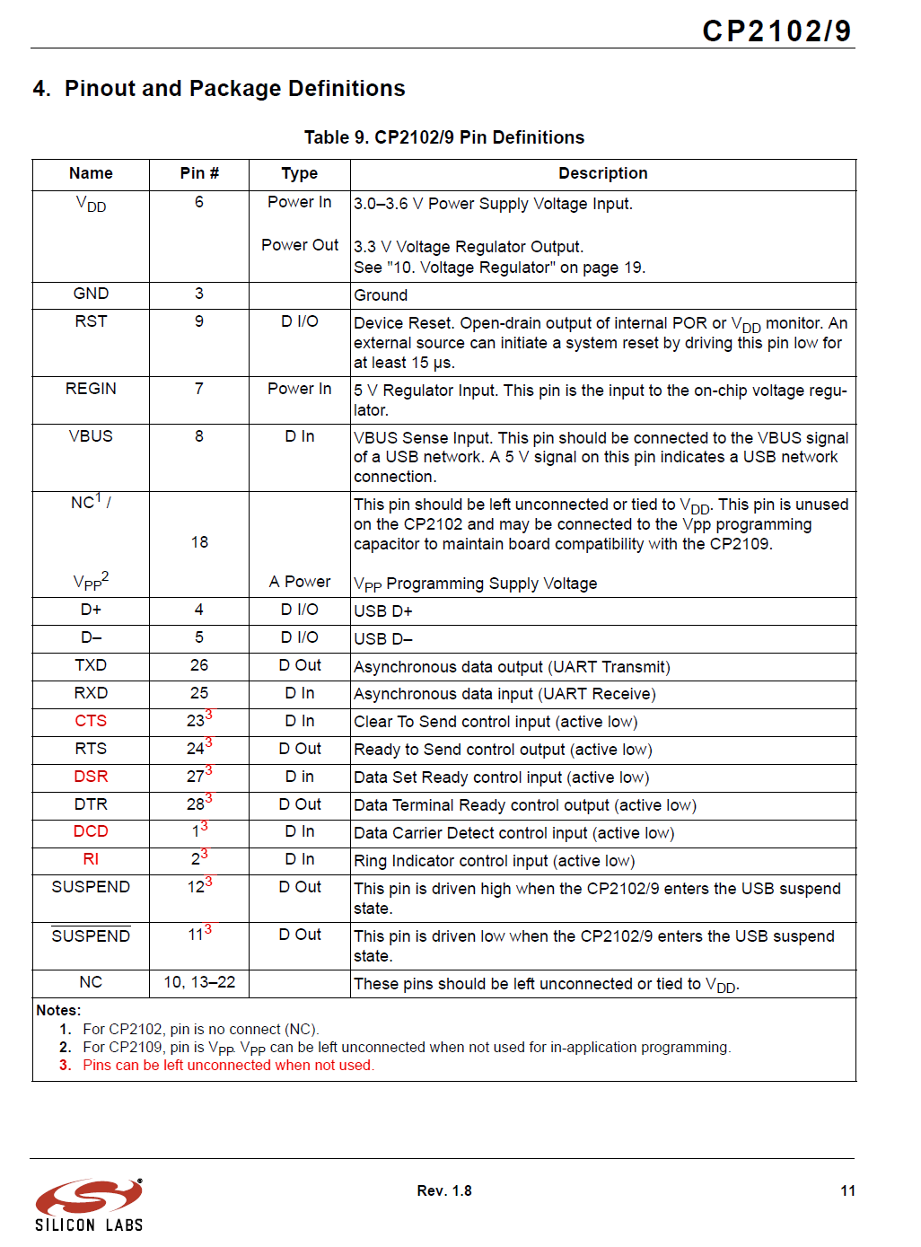
Pinbelegungs-Tabelle des CP2102/9 Mikrocontrollers
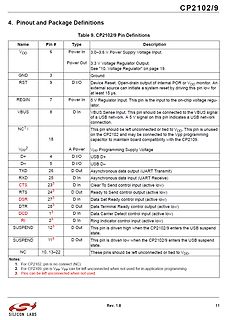
4. Pinout and Package Definitions Table 9. CP2102/9 Pin Definitions Name Pin # Type Description VDD 6 Power In 3.0-3.6 V Power Supply Voltage Input. Power Out 3.3 V Voltage Regulator Output. See "10. Voltage Regulator" on page 19. GND 3 Ground RST
in „Win7: USB-USART Adapter erzeugt hohe CPU Last im System Prozess“ · PC Hard- und Software · · Screenshots
-
PDF
CrumbX128A1_V1.0_infosheet.pdf
dissipation and input voltage. Please see the data sheet for details. USB INTERFACE A USB UART converter CP2102 by Silabs is connected to the MCU's USART0 on PORTF. A standard 5pin mini USB B connector is available onboard and allows for easy connection to a host PC. The CP2102 is always powered from USB bus
in „[V] LCD Display, xMega128 mit USB, AM/FM Radio Empfänger“ · Markt ·
-
Datei
icnova_base.c
setup_board(void) { at32_map_usart(0, 0); // USART 0: /dev/ttyS0, IF-to-USB-UART_Bridge #ifdef ICNOVA_USB_CP2102 at32_map_usart(1, 1); // USART 1: /dev/ttyS0, CP2102 #endif at32_setup_serial_console(0); } static int __init icnova_init(void) { icnova_reserve_pins(); at32_add_system_devices(); at32_add_device_usart(0); #ifdef ICNOVA_USB_CP2102 at32_add_device_usart(1); #endif at32_add_device_pwm((1<<2)); icnova_setup_pwm(2,25000000); // 25MHz icnova_setup_leds(); icnova_setup_buttons(); set_hw_addr(at32_add_device_eth(0, ð_data[0]));
in „Grasshopper und TFT Display“ · Mikrocontroller und Digitale Elektronik ·
-
PDF
NODEMCU_DEVKIT_V1_0.PDF
DTR RTS RST GPIO0 1 1 1 1 D R R S S 1 0 0 1 G D D R C 0 1 1 0 9 8 7 6 5 4 3 2 U2U 2 2 2 2 2 2 2 2CP2102 D R S D DT T C G D D TRXR C N DCDC P I U 2DCD1 NCP I U 2 0 2 1 GNDN P I3U 2RI 2 NCP 19U 2 0 2 0 D_P0 P I U 2D+ 4 NCPIU2018 VDD3V3 D_N0 P I U 2D- 5 NCP I U 2 0 1 7 I1 P1 P I7U 2VDD6 D D NCP 15U 2 0
in „NodmCU ESP8266 nicht zu flashen“ · Mikrocontroller und Digitale Elektronik ·
-
PDF
Crumb128_051120.pdf
32pin headers. Please Note – Previous Crumb128 modules have been shipped with a m preprogrammed CP2102 chip and bootloader - however, since most customers prefer a native USB chip and o microcontroller current Crumb128 modules are not preprogrammed. Please use the native CP210x USB driver for c current
in „Crumb128 Probleme bei der Inbetriebnahme“ · Mikrocontroller und Digitale Elektronik ·
-
Bild
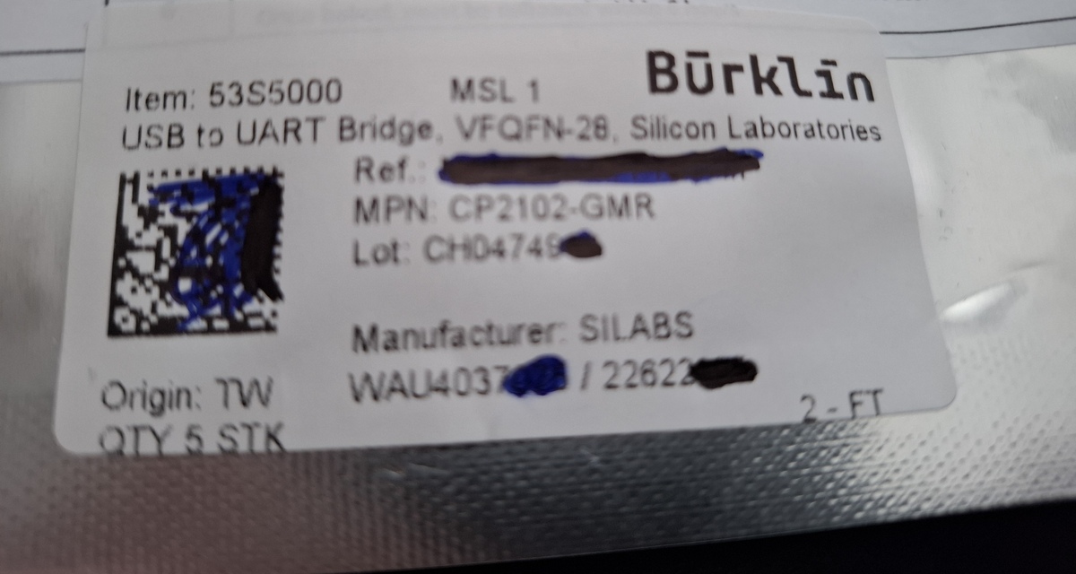
Etikett eines USB-zu-UART-Bridges
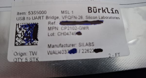
Item: 53S5000 MSL 1 Bürklin USB to UART Bridge, VFQFN-28, Silicon Laboratories Ref.: MPN: CP2102-GMR Lot: CH04749 Manufacturer: SILABS Origin: TW WAU4037 / 22622 QTY 5 STK 2-FT
in „[V] Konvolut Silabs_ICs 5xCP2102 + 5xCP2105 + 10xCP2110 (HID) (25€)“ · Markt · · Fotos
-
PDF
techb_mySmartUSB-light_de_en.pdf
Atmel 6 PIN assignment • 6 PIN Atmel Standard-ISP-Schnittstelle • Industrial standard controller (CP2102) • Industriestandard-Controller (CP2102) USB zu seriell USB to serial converter Konverter • firmware that supports ATMEL AN910 and AN911 • Firmwareprotokolle nach ATMEL AN910/911 oder programming standard
in „Code auf uC übertragen / Programmer“ · Mikrocontroller und Digitale Elektronik ·
-
Bild
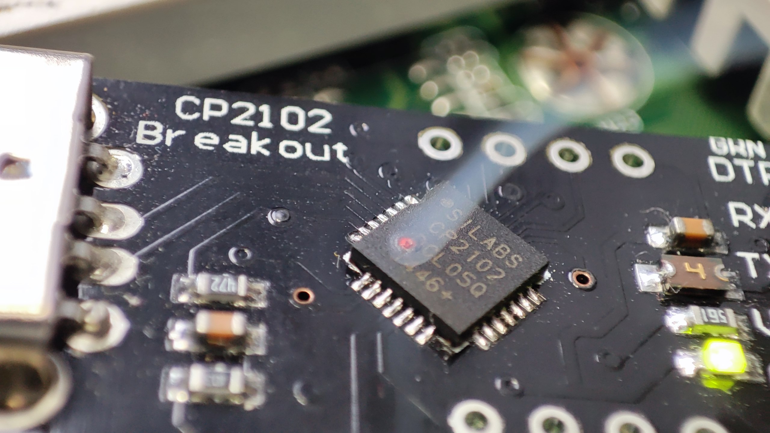
Nahaufnahme eines CP2102 Breakout Boards
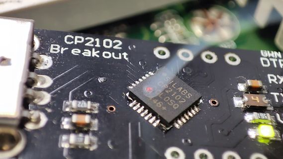
CP2102 Breakout SILABS CP2102 46+ DTR RX TX
in „USB-A Shield und Ground verbinden?“ · HF, Funk und Felder · · Platinenfotos
-
Bild
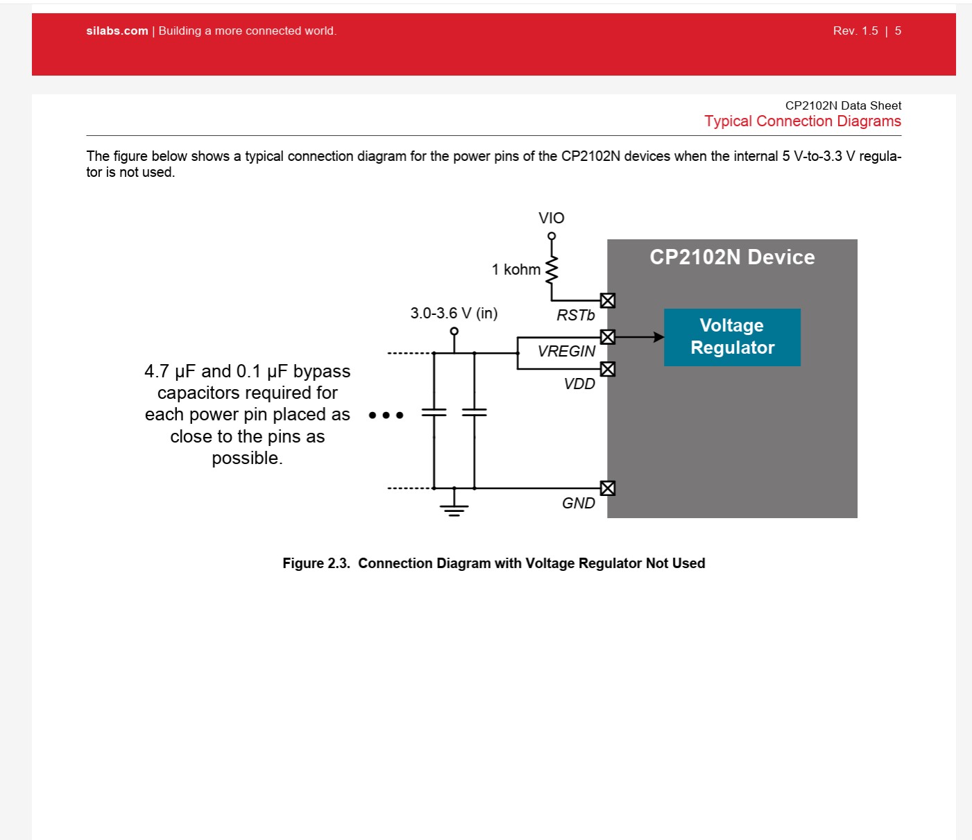
Verbindungsschema für CP2102N ohne internen Spannungsregler
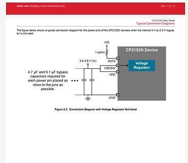
silabs.com | Building a more connected world. Rev. 1.5 | 5 CP2102N Data Sheet Typical Connection Diagrams The figure below shows a typical connection diagram for the power pins of the CP2102N devices when the internal 5 V-to-3.3 V regulator is not used. VIO 1 kohm
in „Sketch Upload via CP2102N schlägt fehl“ · Mikrocontroller und Digitale Elektronik · · Screenshots
-
Bild
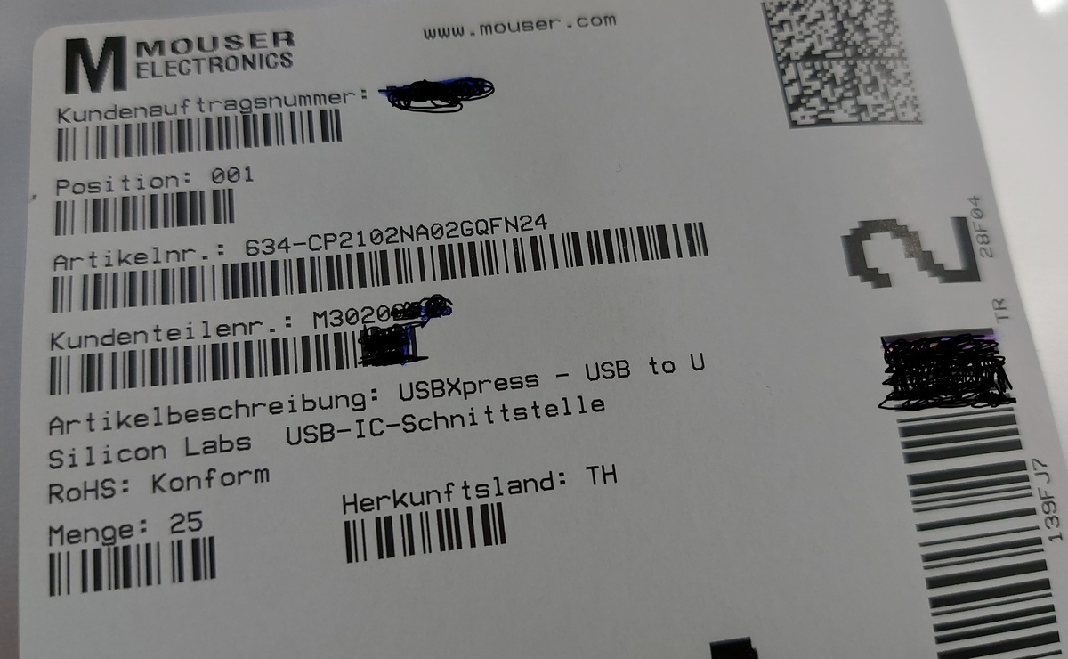
Mouser Electronics Versandetikett
MOUSER ELECTRONICS www.mouser.com Kundenauftragsnummer : Position: 001 Artikelnr.: 634-CP2102NA02GQFN24 Kundenteilenr.: M3020 Artikelbeschreibung: USBXpress - USB to U Silicon Labs USB-IC-Schnittstelle RoHS: Konform Menge: 25 Herkunftsland: TH
in „[V] 25St. Silabs CP2102N (QFN24) USB to UART Bridge (10St für 12€)“ · Markt · · Fotos
-
PDF
-
Bild
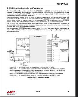
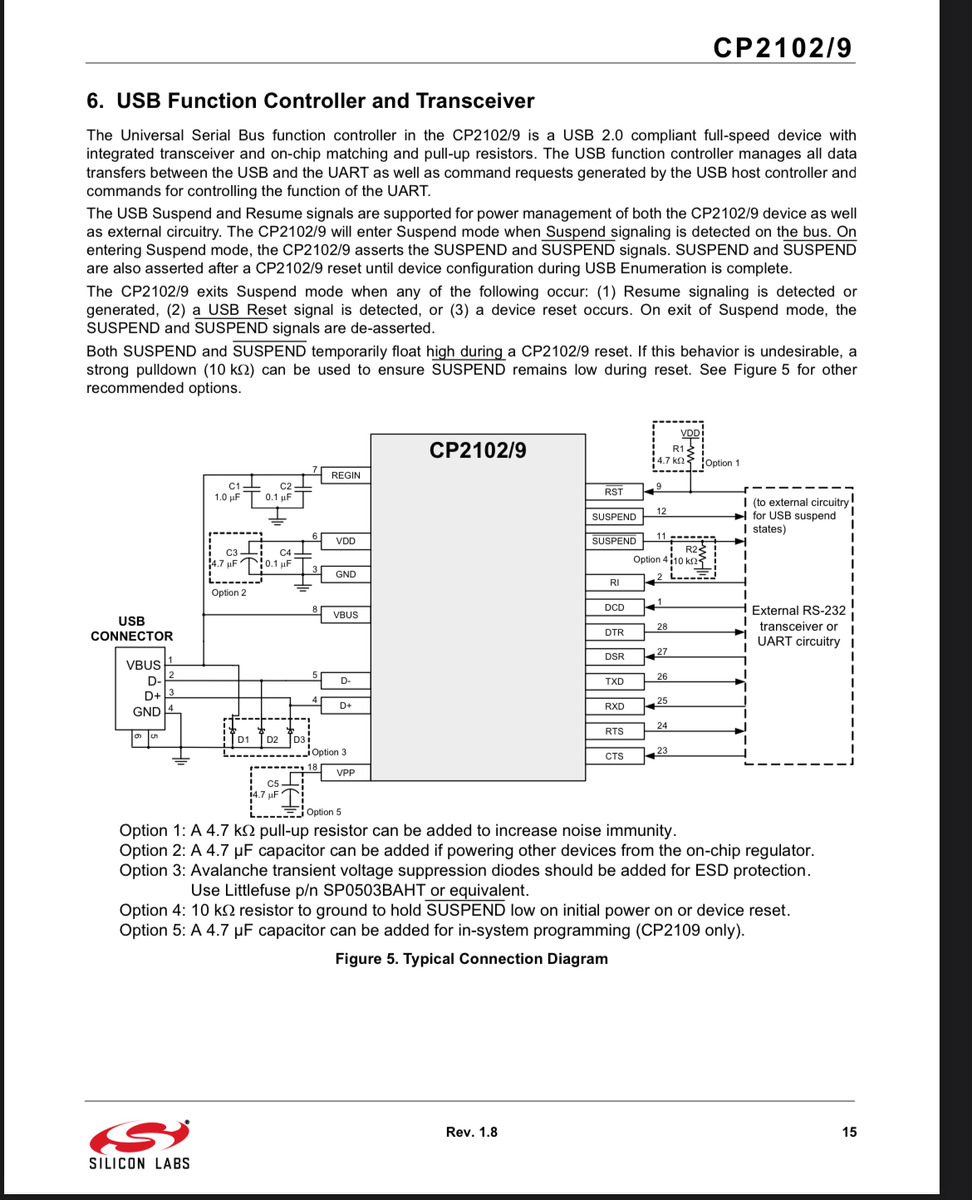
Schaltplan des CP2102/9 USB-Controllers
CP2102/9 6. USB Function Controller and Transceiver USB CONNECTOR VBUS D+ D- GND REGIN C1 1.0 µF C2 0.1 µF VDD C3 4.7 µF C4 0.1 µF SUSPEND SUSPEND RI DCD DSR TXD RXD RTS Option 1: A 4.7 kΩ pull-up resistor
in „ESP32 USB - C Schema“ · Mikrocontroller und Digitale Elektronik · · Schaltpläne
-
Bild
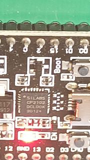
Nahaufnahme einer Leiterplatte mit Silabs CP2102 Chip
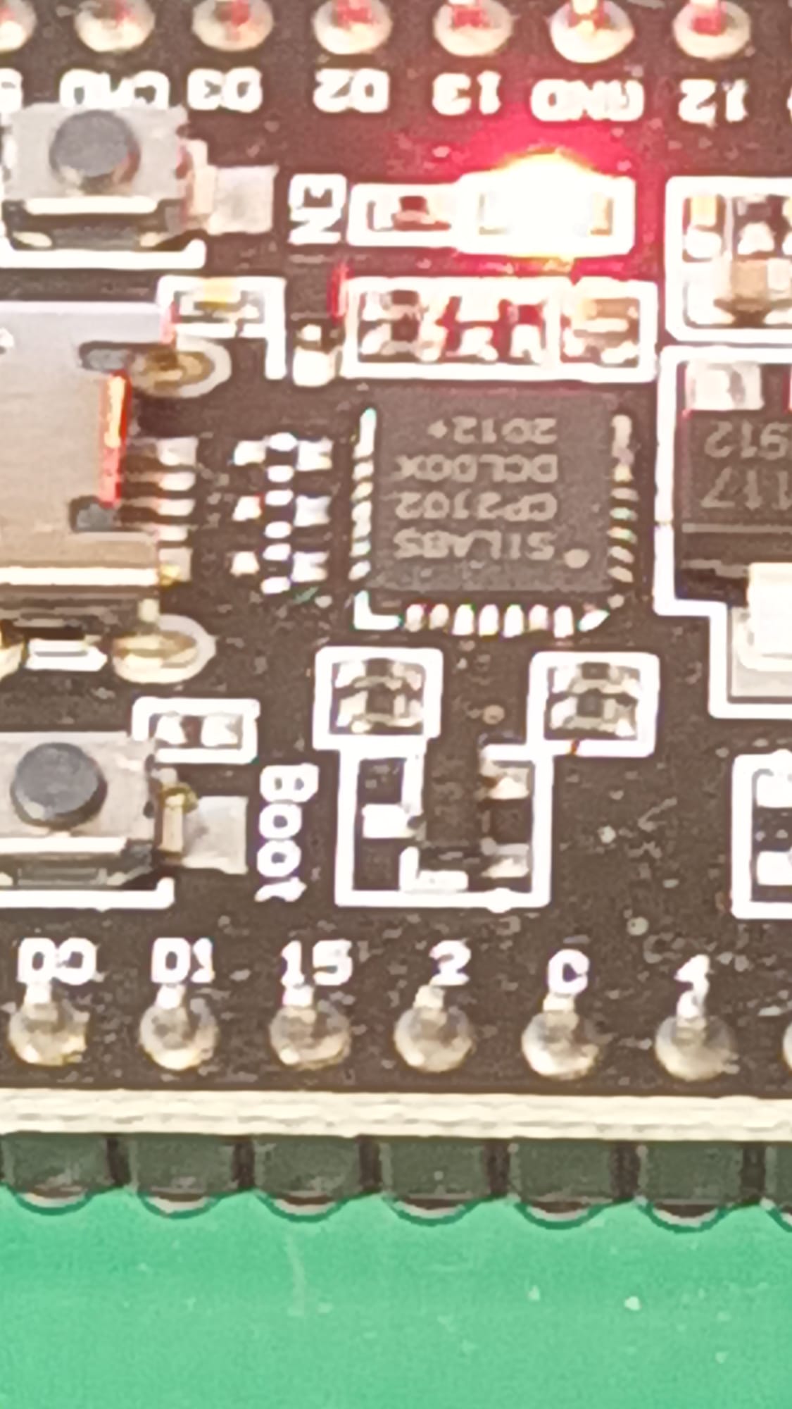
1 2 15 10 00 Boot SILABS CP2102 DCL00X 2012+ 12 GND 13 D2 03 D10
in „ESP32 Dev Kit C V4 mit gefälschten CP2102“ · Mikrocontroller und Digitale Elektronik · · Platinenfotos
-
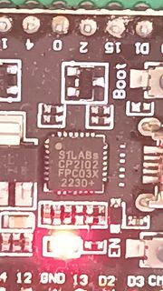
Bild
Nahaufnahme eines Mikrocontroller-Boards mit CP2102 Chip
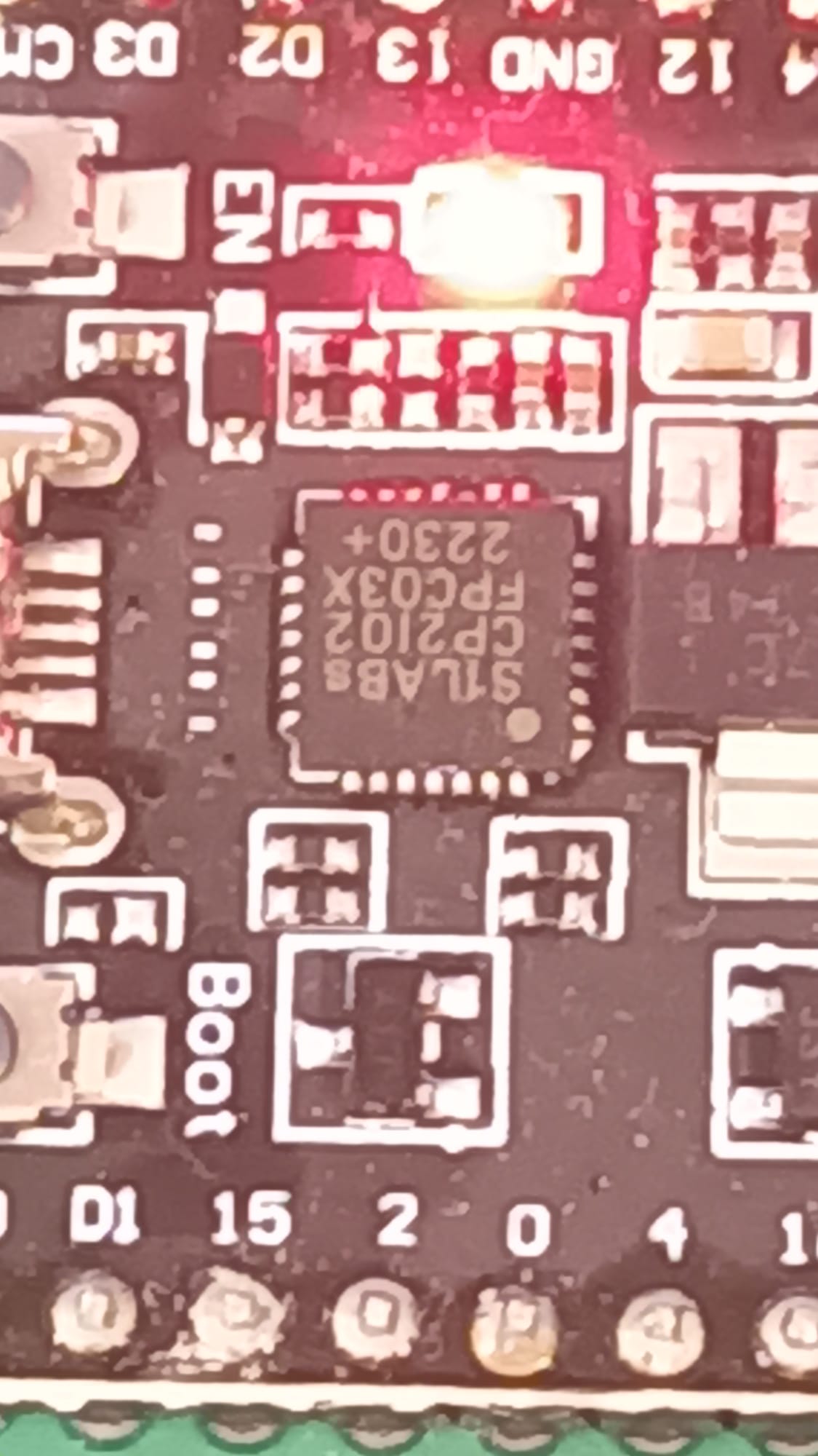
4 20 15 D1 Boot S1LABs CP2102 FPC03X 2230+ 4B 12 GND 13 D2 D3 CM
in „ESP32 Dev Kit C V4 mit gefälschten CP2102“ · Mikrocontroller und Digitale Elektronik · · Platinenfotos
-
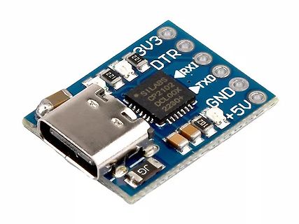
Bild
USB-zu-Seriell Konverter Modul mit CP2102
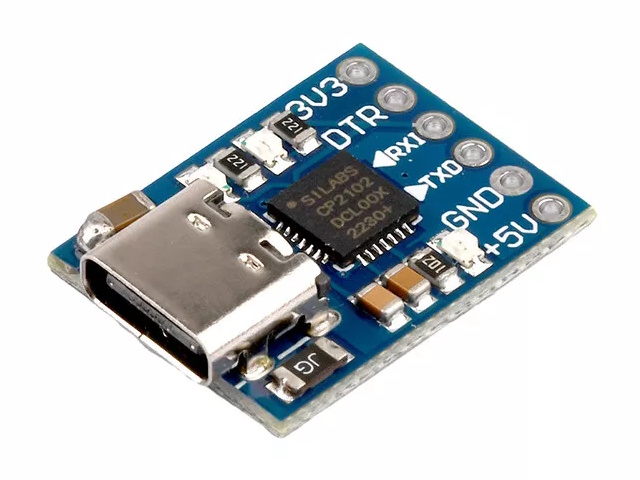
3V3 DTR RX1 TXD GND +5V CP2102 SILABS DCL00X 2230+ 221 102 101
in „Sensor mit UART und PC mit USB direkt verbinden“ · PC Hard- und Software · · Platinenfotos
-
PDF
USB-EMV.pdf
C29 C70 C71 L16 D? 3 D- l l 8 1n5 10µ 10µ 1n5 6 1 D+ h h R16R16 4 V- S S C30 270270 2 7 100n U? CP2102 GNDC 5 2 X? 5 6 6 12 11 SUSPEND 4 3 3 9 /SUSPEND 8 RST VBUS USBLC6-2 U1 5 R19 2 RI REGIN 7 3 417 8 SFH6136 1 180R 28 DCD 6 DTR VDD VCCC 7 2 27 DSR C36 6 26 3 R18 R17 100n 25 TXD lGND 15 15 RXD m 3
in „USB EMV ESD industrielel Umgebung“ · Mikrocontroller und Digitale Elektronik ·
-
PDF
MK_3_02.sch.pdf
18 GND (PCINT25/TXD0)PD1 10 TXD +5VUSB 7 R 1 6 GND (PCINT24/RXD0)PD0 9 RXD 1 D C ATMEGA644PA zum CP2102 N GND USB UART G GND GND 8 7 6 5 2 3V3_CP2102 VCC_EXT +5VUSB 6 DC/DC 5V / 12V C T pin8 SHD V I1 2 3 4 S L=aktiv Vout = 12V 5 Versorgung H Vout = Vin + pin6 = Vout JP3 5V 1 - 2 Verbindungen Bedeutung
in „ATmega 644 Ports Parallel geschaltet MK3 Programmer“ · Mikrocontroller und Digitale Elektronik ·
-
PDF
myAVR_MK2b_zweiVersionen.pdf
PAD2 USB - TTL TXD_USB CP 2102 PAD1 IC1 RXD_USB PB5(SCK) 17 PB4(MISO) 16 C PB3(MOSI/OC2) 15 SPI-SS V PB2(SS/OC1B) 14 X2 PB1(OC1A) 13 0 TH THERMAL PB0(ICP) 12 1 3 5 2 u 5 0 PAD5 C 1 C 1 PD7(AIN1) 11 N 6 VCC PD6(AIN0) 10 O GND_USB
in „myAVR MK2b fehlerhaft, Firmware / Hardware?“ · Mikrocontroller und Digitale Elektronik ·
-
PDF
HTCC-AB01_SchematicDiagram.pdf
1 2 3 4 5 6 7 8 Power management system CP2102: USB to Serial port Header Vin A A Vin D2 USB1 F1 U1 Vin R19 1 1 IN OUT 5 2 R1 22R D_N 6V 500mA 3 C30 1uF U4 4.7K P3 P2 3 R2 22R D_P D1 R4 1N5819 EN USB/Battery/VDD Power Supply Auto Switch System
-
PDF
techb_myavr_board_usb_kurz.pdf
dimensions: 2.54 mm, für Komponenten in Printmontage for components in print assembly USB-Controller: CP2102, SiliconLabs USB-controller: CP2102, SiliconLabs Allgemeine Sicherheitshinweise Safety Guidelines Grundsätzlich ist das myAVR Board USB nur zum Einsatz unter myAVR Board USB is designed for educational
in „DS18S20, Atmega8, AVR Studio“ · Mikrocontroller und Digitale Elektronik ·
-
PDF
techb_mysmartusb-mk2_de_en.pdf
das myAVR Board MK2 USB • Interface for the myAVR Board MK2 USB • Industriestandard-Controller (CP2102) USB zu seriell • Industrial standard controller (CP2102) Konverter USB to serial converter • ATmega8 mit Firmware nach ATMEL AN910 und • ATmega8 with firmware that supports ATMEL AN910 AN911 Programmierstandard
in „Mikro brauch nach übertragen meistens noch einen Reset“ · Mikrocontroller und Digitale Elektronik ·
-
PDF
Targetholder.pdf
TXCAN 1 C3 1 C4 Neupixel Data IO6 IO38 GPIO39 addeafterwarbecauTestPCB sometimdidnaccepprogrammiviaCP2102 7 IO7 IO39 32 WLAN Status 8 33 GPIO40 Voltage Operations Screw Terminal Open Switch1 9 IO15 IO40 34 GPIO41 IO16 IO41 GND Stop Switch1 10 IO17 IO42 35 GPIO42 PWR_FLAG PWR_FLAG Close Switch1 11 36 U0RXD
in „ESP32 Platine funktioniert nicht (Türöffner)“ · Platinen ·
-
PDF
Airframe-Esp32.pdf
GND 2CCO27 R25 R27 CO28 RTS P1uf P0.1uF0402 R28OC 2CIP P9 C29 P P1 CO30I CC0402KRX7R9BB103 DTR 2 1 CP2102-GM D 2DOC 2 1 P0 P 2 GND GND GND 0Ohm 0402 PR GND CR40 GND GND IO21 PIR001 PIR002 PID20 PID201 GND VDD 3V3 R29 1 IP901 PIR292 ROC 013CIP 1R3 2 1 C3 C3C CIC2 PIR001 PIR302 P023CI PI3 PI32 2013CIP 2
in „CP2102 ESP32-S3 USB Verbindung“ · Mikrocontroller und Digitale Elektronik ·
-
PDF
Official_ESP32_NodeMCU_Developmentboard_Datenblatt_AZ-Delivery.pdf
ESP32 NodeMCU Module WLANWiFi Development Board mit CP2102 Datenblatt
in „ESP32 Sensorplatine“ · Mikrocontroller und Digitale Elektronik ·
-
Bild
Blockschaltbild ESP32 PCB und ESP32flasher
ESP32 PCB 3.3V 3V3 EN IO0 IO1 IO3 GND ESP32 ESP32flasher CP2102 3.3V LDO USB-C
in „Vermischte Potentiale“ · Mikrocontroller und Digitale Elektronik · · Schaltpläne
-
PDF
USB-Rs232.pdf
Microcontroller CP2102 bzw. Microcontroller mit Mit USB on board FT232R RS232 Signale (RX, TX, CTR, STR) RS232 Signale USB Signale D+, D-,5Volt, RX, TX, CTR, STR Ground
in „CP2102 (USB->RS232) und FT232R (USB->232R) und Treiber“ · Mikrocontroller und Digitale Elektronik ·
-
Bild
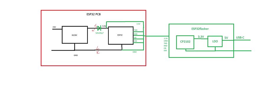
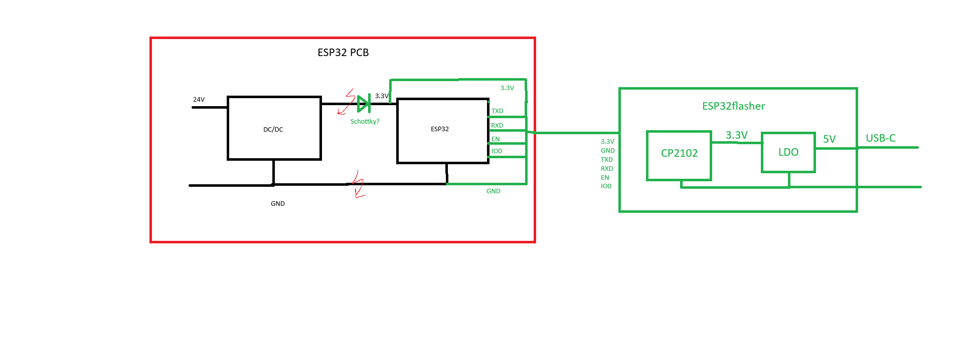
Blockschaltbild ESP32 PCB und ESP32flasher
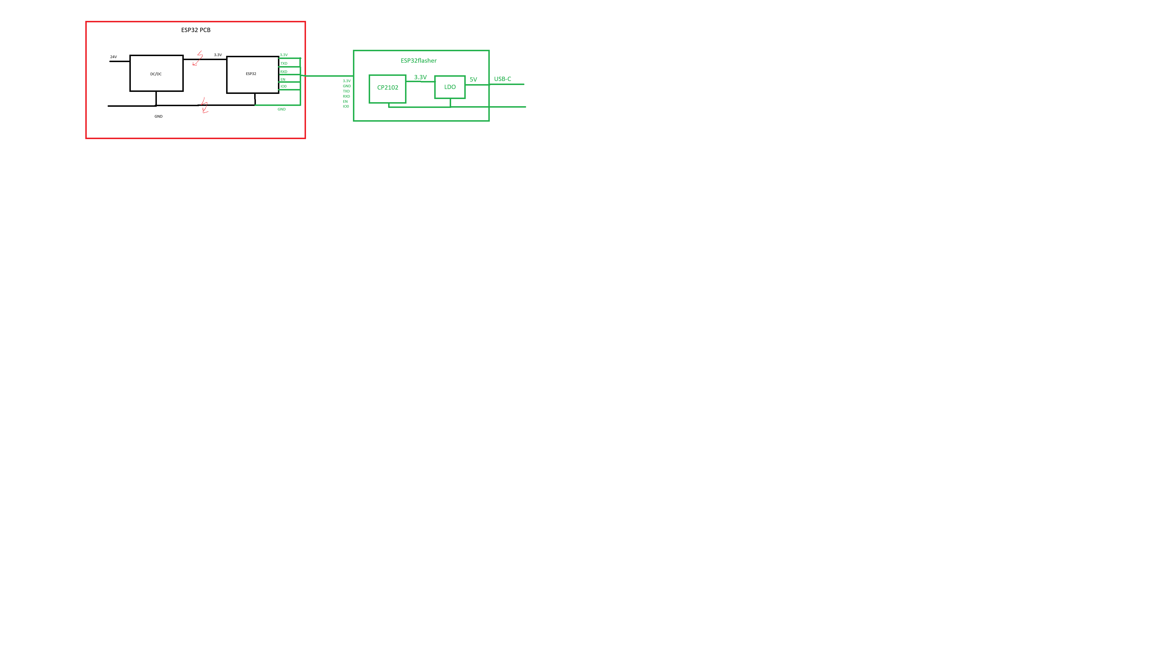
ESP32 PCB 24V DC/DC Schottky? 3.3V ESP32 TXD RXD IO0 GND GND 3.3V ESP32flasher CP2102 3.3V LDO 5V USB-C GND TXD RXD EN IO0
in „Vermischte Potentiale“ · Mikrocontroller und Digitale Elektronik · · Schaltpläne
-
Bild
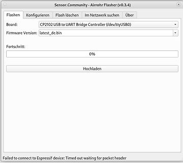
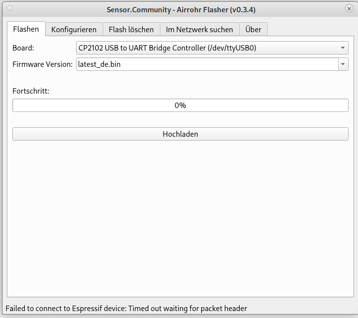
Screenshot eines Firmware-Flash-Tools mit Fehlermeldung
Sensor.Community - Airrhoh Flasher (v0.3.4) Flashen Konfigurieren Flash löschen Im Netzwerk suchen Über Board: CP2102 USB to UART Bridge Controller (/dev/ttyUSB0) Firmware Version: latest_de.bin Fortschritt: 0% Hochladen Failed to connect to Espressif device: Timed out waiting for packet header
in „NodmCU ESP8266 nicht zu flashen“ · Mikrocontroller und Digitale Elektronik · · Screenshots
-
Bild
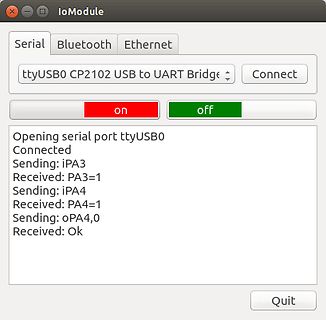
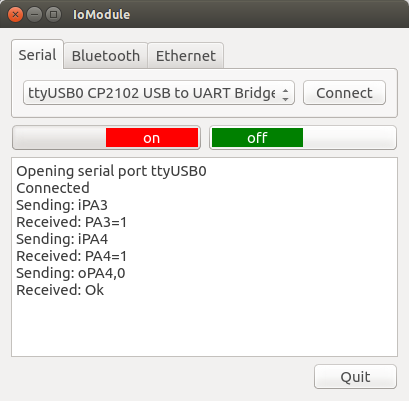
Screenshot einer Software zur seriellen Kommunikation
IoModule Serial Bluetooth Ethernet ttyUSB0 CP2102 USB to UART Bridge Connect on off Opening serial port ttyUSB0 Connected Sending: iPA3 Received: PA3=1 Sending: iPA4 Received: PA4=1 Sending: oPA4,0 Received: Ok Quit

in „Wie geht Win-COM-Kanal auswahl bei PiPico“ · Mikrocontroller und Digitale Elektronik · · Screenshots
-
Bild
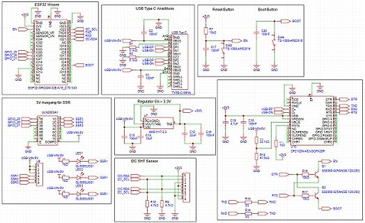
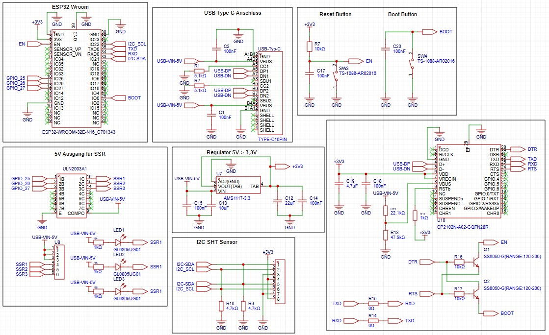
Schaltplan eines ESP32-basierten Systems mit Spannungsregler und Sensoren
Button, Boot Button, ULN2003A1, SSR1 bis SSR3, Regulator 5V -> 3,3V, AMS117-3.3, I2C SHT Sensor, CP2102N-A02-GQFZN2B8, SS8050-G(RANGE:120-200)
in „ESP32-Wroom Platine erstellen“ · Platinen · · Schaltpläne
-
Bild
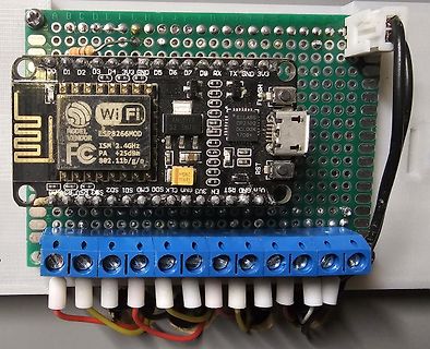
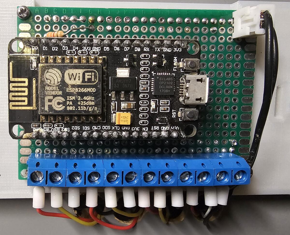
ESP8266 Mikrocontroller auf Erweiterungsplatine mit Klemmenblock
Wi Fi ESP8266MOD AMS1117 3.3 DN71 CP2102 DCLOOX 1708+ FLASH RST D0 D1 D2 D3 3V3 GND D5 D7 RX TX GND 3V3 SO D2 D3 RST SO2 D1 SO D0 CMD GND EN 3V3 CLK GND RST D8
in „ESP8266 mehrere Temperaturfühler mit Display“ · Mikrocontroller und Digitale Elektronik · · Platinenfotos