-
Datei
imu.h
0x16 #define MPU6050_RA_ZG_OFFS_USRH 0x17 //[15:0] ZG_OFFS_USR #define MPU6050_RA_ZG_OFFS_USRL 0x18 #define MPU6050_RA_SMPLRT_DIV 0x19 #define MPU6050_RA_CONFIG 0x1A #define MPU6050_RA_GYRO_CONFIG 0x1B #define MPU6050_RA_ACCEL_CONFIG 0x1C #define MPU6050_RA_FF_THR 0x1D #define MPU6050_RA_FF_DUR 0x1E #define MPU6050_RA_MOT_THR 0x1F #define MPU6050_RA_MOT_DUR 0x20 #define MPU6050_RA_ZRMOT_THR 0x21 #define MPU6050_RA_ZRMOT_DUR 0x22 #define MPU6050_RA_FIFO_EN
in „atmega 328 und MPU 9150“ · Mikrocontroller und Digitale Elektronik ·
-
Datei
main.c
; MPU6050_Write(MPU6050_DEFAULT_ADDRESS, MPU6050_RA_PWR_MGMT_1, MPU6050_CLOCK_PLL_ZGYRO);//PLL with Z axis gyroscope reference MPU6050_Write(MPU6050_DEFAULT_ADDRESS, MPU6050_RA_CONFIG, 0x01); //DLPF_CFG = 1
in „STM32F103 + I2C + MPU6050 - DMA“ · Mikrocontroller und Digitale Elektronik ·
-
Datei
main.c
MPU6050_ACONFIG_YA_ST_BIT 6 #define MPU6050_ACONFIG_ZA_ST_BIT 5 #define MPU6050_ACONFIG_AFS_SEL_BIT 4 //Wird in Funktion MPU6050_setFullScaleAccelRange() benutzt #define MPU6050_ACONFIG_AFS_SEL_LENGTH 2 /
in „ISR Probleme“ · Mikrocontroller und Digitale Elektronik ·
-
Datei
main.c
(4,2," "); LCD_Text(4,2,str); Delay10KTCYx(125); } } void MPU6050_Init(void) { //if(MPU6050_Read_Reg(MPU6050_RA_WHO_AM_I)==0x68) // LCD_Text_Rom(2,1,"OK"); MPU6050_Write_Reg(MPU6050_RA_SMPLRT_DIV,159); // 8000Hz/(159+1)=50Hz MPU6050_Write_Reg(MPU6050_RA_CONFIG,0x00); MPU6050_Write_Reg(MPU6050_RA_GYRO_CONFIG,0b00011000); // 2000 °/s MPU6050_Write_Reg(MPU6050_RA_ACCEL_CONFIG,0b00011000); // +/- 16 g MPU6050_Write_Reg(MPU6050_RA_INT_PIN_CFG,0b00100000); // MPU6050_Write_Reg
in „PIC18 + MPU6050 funktionier nicht“ · Mikrocontroller und Digitale Elektronik ·
-
Datei
main.c
MASTER, SLEW_ON); // SSP1ADD=49; // 100kHz @ 20MHz SSP1ADD=12; // 400kHz @ 20MHz LCD_Text_Rom(1,1,"MPU6050"); while(1) MPU6050_Init(); } void MPU6050_Init(void) { if(MPU6050_Read_Reg(MPU6050_RA_WHO_AM_I)==0x68) LCD_Text_Rom(2,1,"OK"); MPU6050_Write_Reg(MPU6050_RA_SMPLRT_DIV,159); // 8000Hz/(159+1)=50Hz MPU6050_Write_Reg(MPU6050_RA_CONFIG,0x00); MPU6050_Write_Reg(MPU6050_RA_GYRO_CONFIG,0b00011000); // 2000 °/s MPU6050_Write_Reg(MPU6050_RA_ACCEL_CONFIG,0b00011000); // +/- 16 g MPU6050_Write_Reg(MPU6050_RA_INT_PIN_CFG
in „PIC18 + MPU6050 funktionier nicht“ · Mikrocontroller und Digitale Elektronik ·
-
PDF
MPU-6050.pdf
. The table below outlines these differences: 7 of 52 Document Number: PS-MPU-6000A-00 MPU-6000/MPU-6050 Product Specification Revision: 3.4 Release Date: 08/19/2013 Primary Differences between MPU-6000 and MPU-6050 Part / Item MPU-6000 MPU-6050 VDD 2.375V-3.46V 2.375V-3.46V VLOGIC n/a 1.71V to VDD 2
in „MPU 6050 Gyrosensor auslesen“ · Mikrocontroller und Digitale Elektronik ·
-
PDF
PS-MPU-6000A-00v3.4.pdf
below outlines these differences: 7 of 52 Document Number: PS-MPU-6000A-00 Revision: 3.4 MPU-6000/MPU-6050 Product Specification Release Date: 08/19/2013 Primary Differences between MPU-6000 and MPU-6050 Part / Item MPU-6000 MPU-6050 VDD 2.375V-3.46V 2.375V-3.46V VLOGIC n/a 1.71V to VDD Serial Interfaces
in „Neigungswinkelinkelmessung beweglicher Teile“ · Analoge Elektronik und Schaltungstechnik ·
-
Datei
MPU6050.c
/* * MPU6050.c * * Created: 05.11.2014 14:53:44 * Author: Marcel */ #define F_CPU 12000000UL #include <util/delay.h> #include "i2c_master.h" #define MPU6050_ADDRESS_WRITE 0xD0 #define MPU6050_ADDRESS_READ 0xD1 int ax = 0; int ay = 0; int az = 0; int gx = 0; int gy = 0; int gz = 0; void init_MPU6050(){ i2c_start(MPU6050_ADDRESS_WRITE); // Set Clock Source i2c_write(0x6B); i2c_write(0x80); i2c_stop(); _delay_ms(50); i2c_start(MPU6050_ADDRESS_WRITE); // Set Clock Source i2c_write(0x6B); i2c_write
in „MPU 6050 Gyrosensor auslesen“ · Mikrocontroller und Digitale Elektronik ·
-
PDF
MPU-6050A-Register.pdf
(408) 988-8104 Revision: 4.0 Website: www.invensense.com Release Date: 03/09/2012 MPU-6000 and MPU-6050 Register Map and Descriptions Revision 4.0 CONFIDENTIAL & PROPRIETARY 1 of 47 MPU-6000/MPU-6050 Register Map and Document Number: RM-MPU-6000A-00 Revision: 4.0 Descriptions Release Date: 03/09/2012
in „MPU6050 Z-Achse Keine Werte“ · Mikrocontroller und Digitale Elektronik ·
-
Datei
MPU6050_calibration.ino
DEALINGS IN THE SOFTWARE. ========================================================= */ // I2Cdev and MPU6050 must be installed as libraries #include "I2Cdev.h" #include "MPU6050.h" #include "Wire.h" /////////////////////////////////// CONFIGURATION ///////////////////////////// //Change this 3 variables
in „MPU-6050 Auslesen Prblem“ · Mikrocontroller und Digitale Elektronik ·
-
Datei
Gyros.c
LCD_init(); //LCD initialisieren __delay_ms(Ganz); Init_Master(); //I²C als Master initialisieren Init_MPU6050(); //MPU6050 initialisieren while (1){ I2C_Master_Send (XA_OFFS_H, 0); Sig_Char_an_LCD (I2C_Master_Read (XA_OFFS_H), 16); //Sig_Char_an_LCD: Zweierkomplement an LCD mit Vorzeichen ausgeben Sig_Char_an_LCD
in „MPU6050 Z-Achse Keine Werte“ · Mikrocontroller und Digitale Elektronik ·
-
Datei
config.h
by Alex //#define FREEIMUv035_BMP // FreeIMU v0.3.5_BMP //#define FREEIMUv04 // FreeIMU v0.4 with MPU6050, HMC5883L, MS561101BA <- confirmed by Alex //#define FREEIMUv043 // same as FREEIMUv04 with final MPU6050 (with the right ACC scale) //#define NANOWII // the smallest multiwii FC based on MPU6050
in „Problem mit meinem Projekt (Quadrocopter)“ · Mikrocontroller und Digitale Elektronik ·
-
Datei
MPU6050_DMP6.ino
OTHER DEALINGS IN THE SOFTWARE. =============================================== */ // I2Cdev and MPU6050 must be installed as libraries, or else the .cpp/.h files // for both classes must be in the include path of your project #include "I2Cdev.h" #include "MPU6050_6Axis_MotionApps20.h" //#include "MPU6050
in „MPU-6050 Auslesen Prblem“ · Mikrocontroller und Digitale Elektronik ·
-
Datei
Mixed_Reality_Space_Forum.txt
include <PubSubClient.h> #include <SPI.h> #include <Ethernet.h> #include <PubSubClient.h> #include <MPU6050_tockn.h> #include <Wire.h> MPU6050 mpu6050(Wire); const char* ssid = ""; const char* password = ""; const char* mqtt_server = ""; WiFiClient espClient; PubSubClient client(espClient); long lastMsg
in „char in int umwandeln“ · Mikrocontroller und Digitale Elektronik ·
-
Bild
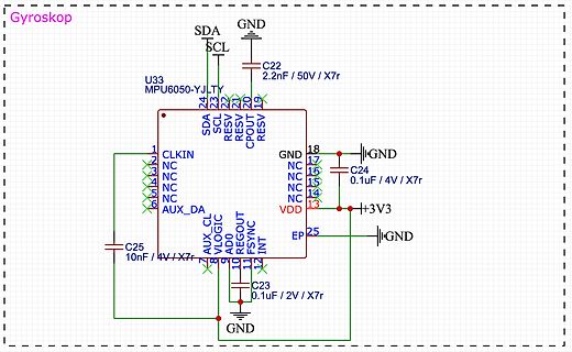
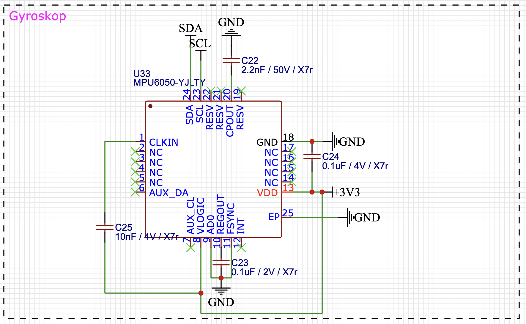
Schaltplan eines MPU6050 Gyroskops
Gyroskop SDA SCL GND U33 MPU6050-YJLTY 24 23 22 21 20 19 SDA SCL RESV RESV CPOUT RESV GND 18 17 NC 16 15 NC 15 NC 14 NC 13 VDD 3V3 25 EP GND INT FSVNC REGOUT VLOGIC AUX_CL AUX_DA 6 5 4 3 2 CLKIN NC NC NC 9 AD0 10 11 12 C25 10nF
in „Es wird nur ein I2C Gerät erkannt“ · Mikrocontroller und Digitale Elektronik · · Schaltpläne
-
Datei
pinout.txt
P3.1 AIN7, CPP1 Partially Connected to motor ctrl circuit 1 (sense?) 6 P3.2 T0EX,STADC,INT0 YES MPU6050, pin 12 (interrupt) 7 P3.4 SDA, T0 YES MPU6050, pin 24 (SDA) 8 P3.5 SCL, T1 YES MPU6050, pin 23 (SCL) 9 P3.6 T1EX,CK0,CPO0 Partially Connected to test pad 10 P5.1 XTAL2 NC? Not connected? 11 P5.0
in „Hackbarer(?) 21 EUR Quadcopter“ · Mikrocontroller und Digitale Elektronik ·
-
Bild
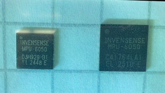
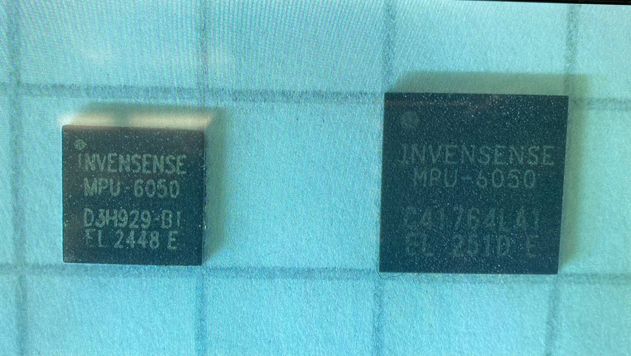
Zwei InvenSense MPU-6050 Sensoren
INVENSENSE MPU-6050 D3H929-B1 EL 2448 E INVENSENSE MPU-6050 C41764L41 EL 2510 E
in „IMU MPU6050 Erdbeschleunigung nicht gleich 1“ · Mikrocontroller und Digitale Elektronik · · Fotos
-
Bild
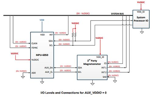
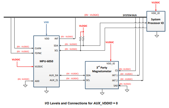
Blockschaltbild der I/O-Pegel und Verbindungen
SYSTEM BUS VLOGIC VDD_IO System Processor IO (0V - VLOGIC) VDD INT SDA SCL MPU-6050 VLOGIC (0V - VLOGIC) AUX_DA AUX_CL ADD 3rd Party Magnetometer VDD_IO CS INT 1 INT 2 SA0 SDA SCL (0V - VLOGIC) I/O Levels and Connections for AUX_VDDIO = 0
in „Es wird nur ein I2C Gerät erkannt“ · Mikrocontroller und Digitale Elektronik · · Diagramme
-
Bild
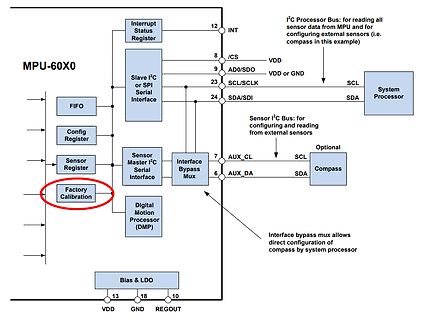
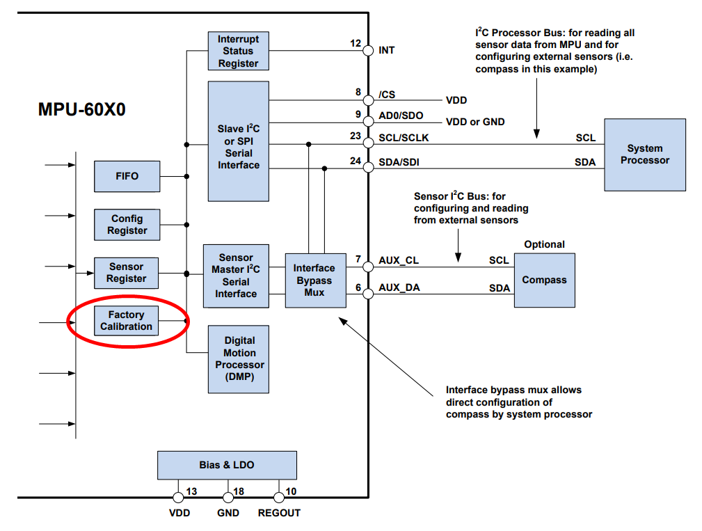
Blockschaltbild MPU-60X0 Sensor Interface
MPU-60X0 Interrupt Status Register 12 INT I2C Processor Bus: for reading all sensor data from MPU and for configuring external sensors (i.e. compass in this example) 8 /CS VDD 9 AD0/SDO VDD or GND 23 SCL/SCLK SCL 24 SDA/SDI SDA System Processor Sensor I2C Bus: for configuring and reading from external sensors FIFO Slave I2C or SPI Serial Interface AUX_CL SCL Optional Sensor Register Sensor Master I2C Serial Interface Interface Bypass Mux AUX_DA SDA Compass Factory Calibration Digital Motion Processor (DMP) Interface bypass mux allows direct configuration of compass by system processor 13 VDD 18
in „IMU MPU6050 Erdbeschleunigung nicht gleich 1“ · Mikrocontroller und Digitale Elektronik · · Diagramme
-
Datei
BalancingWii.ino
- http://www.multiwii.com/forum/viewtopic.php?f=7&t=4787 Hardware: - Arduino nano (atmega328p) - mpu6050 gyro-accelerometer (GY_521) - any RC receiver with CPPM (ppmsum) output OR serial Bluetooth module like HC-05 - A4988 motor drivers with 1/8 microstepping configuration (see http://www.pololu.com/
-
Bild
Text zum MPU-6050 MEMS MotionTracking Device
MPU-6050 Six-Axis (Gyro + Accelerometer) MEMS MotionTracking™ Device
in „Beschleunigungssenor in Weg umrechnen“ · Mikrocontroller und Digitale Elektronik · · Screenshots
-
Bild
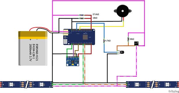
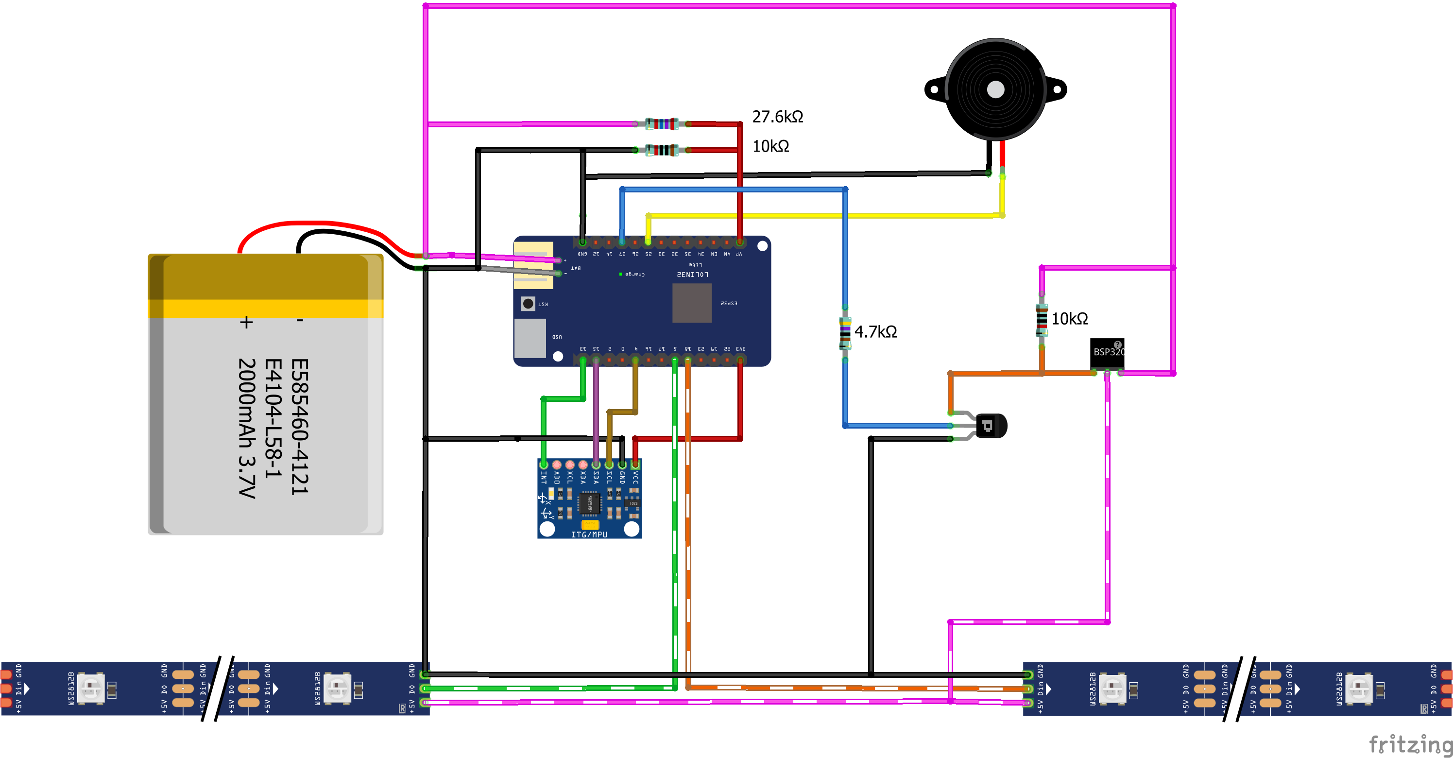
Schaltplan mit LoLin32, Akku, MPU6050 und Sensoren
27.6kΩ, 10kΩ, E585460-4121, 2000mAh 3.7V, LoLin32, 4.7kΩ, 10kΩ, MPU6050, fritzing
in „LED-Wasserwaage aus Bastelheft“ · Analoge Elektronik und Schaltungstechnik · · Schaltpläne
-
Bild
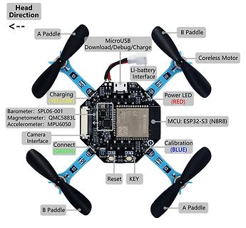
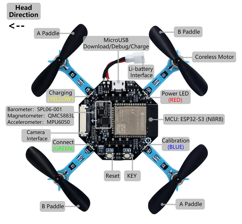
Beschriftetes Foto eines Mikrocontroller-Drohnen-Boards
Motor Charging (YELLOW) Power LED (RED) Barometer: SPL06-001 Magnetometer: QMC5883L Accelerometer: MPU6050 Camera Interface Connect (GREEN) Calibration (BLUE) RST KEY
in „OrangePi mit Loongson-Prozessor, Wolfspeed in CH11-”Insolvenz”, MCUXpresso-Update uvam“ · Mikrocontroller und Digitale Elektronik · · Fotos
-
Bild
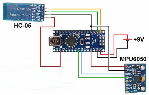
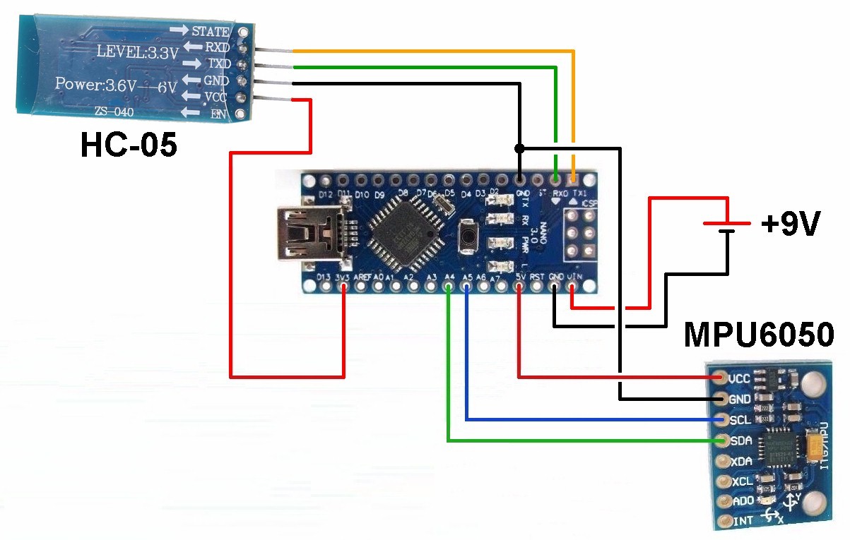
Aufbau mit Arduino Nano, HC-05 Bluetooth und MPU6050 Sensor
GND VCC EN D12 D11 D10 D9 D8 D6 D5 D4 D3 D2 D13 3V3 AREF A0 A1 A2 A3 A4 A5 5V RST GND VIN NANO +9V MPU6050 VCC GND SCL SDA XDA XCL AD0 INT
in „Physikprojekte“ · Offtopic · · Fotos
-
PDF
Stromlaufplan.pdf
NC Brems GND IN + OUT + SP G22 SN TXD IN - OUT - G34 RXD G35 G21 G32 GND G33 G19 G25 G18 G26 G5 MPU6050 G27 G17 VCC G14 G16 GND G4 G12 SCL GND G0 SDA G13 G2 XDA SD2 G15 XCL SD3 SD1 AD0 CMD SD0 INT V5 CLK
in „Schon der zweiten ESP32 abgeraucht“ · Fahrzeugelektronik ·
-
Datei
MPU-9150_ACC_GYRO.txt
I2cinit '--- (107) Power Management 1 --- I2cstart 'start condition I2cwbyte &HD0 'write adress of MPU-6050 I2cwbyte 107 'Register 107 Power Management 1 I2cwbyte &B00001011 'No Reset / No Sleep / No Cycle / Temp_Sens: Dis / Clock Source: Z-Gyro I2cstop Do Call Read_gyro Gyrox = Tmp_gyrox(2) * 256 Gyrox
in „MPU-9150 Kompass mit BASCOM auslesen“ · Mikrocontroller und Digitale Elektronik ·
-
PDF
SAT-L1_Flight_Controller.pdf
D 0.1µF C8 IO21 N 36 MPU_SCL G 2.2nF IO22 37 8 IO23 1 GND 10 U2 +3.3V V_AKKU IO25 +3.3V GND 11 MPU-6050 IO26 R4 PWR_FLAG 12 R3 IO27 GND 8 4.7k B 1 IO32 4.7k B V_AKKU 9 N +5V IO33 I 6 MPU_SDA D 5 IO34 MPU_SCL N 2 8 6 C2 7 C1 G GND 7 U D IO35 T L C_Small N C_Small U G O CH340C_DTR 3 15 8 9 +5V 1 3 3 F
in „Prüfung Schaltplan Flight Controller“ · Mikrocontroller und Digitale Elektronik ·
-
PDF
Quad_Schaltplan.pdf
PCINT28/OC1B)PD4 12 M3 N 4.7K CLKIN GND 100nF N N 28 GND (PCINT27/INT1)PD3 11 G I2C_ADDRESS_SEL MPU-6050 G G 18 GND (PCINT26/INT0)PD2 10 GND 100nF 100nF 6 GND (PCINT25/TXD0)PD1 9 100nF100nF GND (PCINT24/RXD0)PD0 +5V ATMEGA644A 12.12.2012 18:29:05 f=1.42 C:\Users\Dominik\Documents\eagle\Quadrocopter\Prototyp2
-
Datei
compile_Tasmota_stable_in_docker_container_versuch3.txt
Indexing .pio/build/tasmota/libf56/libBM8563_RTC.a Compiling .pio/build/tasmota/libcd3/I2Cdevlib-MPU6050/MPU6050.cpp.o Compiling .pio/build/tasmota/lib5d4/Mutichannel_Gas_Sensor/MutichannelGasSensor.cpp.o Compiling .pio/build/tasmota/lib9aa/ArduinoNTPd/NTPPacket.cpp.o Archiving .pio/build/tasmota/libe29
in „Dlock 11827 und Tasmota - compilieren für FW-Update“ · Haus & Smart Home ·
-
PDF
Copter00.pdf
1 CLKIN G D V V CLKOUT 22 O V R R 24 V 6 MP_SDA 23 SDA IC3 AUX_DA 7 MP_SCL 9 SCL AUX_CL AD0 12 MPU-6050 MP_IRQ INT U T N O U S N E P F G R C 1 1 1 2 GND Quadcopter JD-385 Sensoren 0.1 21.11.2013 09:00:56 D:\Eagle-Daten\projects\Quadcopter\Copter00.sch (Sheet: 4/5) D D N N 1 3 G G 3 1 S7 S13 1 k 2S12
in „Hackbarer(?) 21 EUR Quadcopter“ · Mikrocontroller und Digitale Elektronik ·
-
PDF
Copter00.pdf
1 CLKIN G D V V CLKOUT 22 O V R R 24 V 6 MP_SDA 23 SDA IC3 AUX_DA 7 MP_SCL 9 SCL AUX_CL AD0 12 MPU-6050 MP_IRQ INT U T N O U S N E P F G R C 1 1 1 2 GND Quadcopter JD-385 Sensoren 0.1 21.04.2014 09:36:19 D:\Eagle-Daten\projects\Quadcopter\Copter00.sch (Sheet: 4/5) GND GND GND GND GND GND C27 C28 9 k
in „Hackbarer(?) 21 EUR Quadcopter“ · Mikrocontroller und Digitale Elektronik ·
-
PDF
PARTS_CLEARING_-_Sheet1.pdf
breakout board E05 OVP €3.00 2 https://www.sparkfun.c http://i.ebayimg.c 10€ sparkfun available MPU6050 breakout, not from sparkfun! Sparkfun link just for reference E06 OVP €5.00 2 https://www.sparkfun.c http://i.ebayimg.c 10€ ebay available sparkfun just for reference, mine is ebay esp8266 module
in „[V] Rigol DS1052E, Labornetzteil, Robotikteile, Modellbau“ · Markt ·
-
Datei
dir.txt
dtbo 17.12.2020 16:34 1.446 miniuart-bt.dtbo 17.12.2020 16:34 1.221 mmc.dtbo 17.12.2020 16:34 796 mpu6050.dtbo 17.12.2020 16:34 2.826 mz61581.dtbo 17.12.2020 16:34 2.597 ov5647.dtbo 17.12.2020 16:34 2.356 papirus.dtbo 17.12.2020 16:34 569 pi3-act-led.dtbo 17.12.2020 16:34 954 pi3-disable-bt.dtbo 17.12.2020
in „Raspberry Pi bootet nicht“ · Mikrocontroller und Digitale Elektronik ·
-
Datei
compile_Tasmota_stable_in_docker_container.txt
tasmota32-DE/libcfa/LibTeleinfo/LibTeleinfo.cpp.o Compiling .pio/build/tasmota32-DE/libcd3/I2Cdevlib-MPU6050/MPU6050.cpp.o Compiling .pio/build/tasmota32-DE/lib5d4/Mutichannel_Gas_Sensor/MutichannelGasSensor.cpp.o Compiling .pio/build/tasmota32-DE/lib9aa/ArduinoNTPd/NTPPacket.cpp.o Archiving .pio/build/tasmota32
in „Dlock 11827 und Tasmota - compilieren für FW-Update“ · Haus & Smart Home ·
-
Datei
config-mod-LK511-mt7623n-BPiR2.txt
CONFIG_BMI160_I2C is not set # CONFIG_BMI160_SPI is not set # CONFIG_KMX61 is not set # CONFIG_INV_MPU6050_I2C is not set # CONFIG_INV_MPU6050_SPI is not set # CONFIG_IIO_ST_LSM6DSX is not set # # Light sensors # # CONFIG_ADJD_S311 is not set # CONFIG_AL3320A is not set # CONFIG_APDS9300 is not set # CONFIG_APDS9960

in „Linux Kernel 5.1.1. auf dem BPi-R2“ · PC Hard- und Software ·